Phase-space properties of magneto-optical traps utilising micro-fabricated gratings.
Abstract
We have used diffraction gratings to simplify the fabrication, and dramatically increase the atomic collection efficiency, of magneto-optical traps using micro-fabricated optics. The atom number enhancement was mainly due to the increased beam capture volume, afforded by the large area (cm2) shallow etch (nm) binary grating chips. Here we provide a detailed theoretical and experimental investigation of the on-chip magneto-optical trap temperature and density in four different chip geometries using 87Rb, whilst studying effects due to MOT radiation pressure imbalance. With optimal initial MOTs on two of the chips we obtain both large atom number ) and sub-Doppler temperatures K) after optical molasses.
Dept. of Physics, SUPA, University of Strathclyde, Glasgow G4 0NG, UK
(020.3320) Laser cooling; (020.7010) Laser trapping.
References
- [1] S. Chu, L. Hollberg, J. E. Bjorkholm, A. Cable, and A. Ashkin, “Three-dimensional viscous confinement and cooling of atoms by resonance radiation pressure,” Phys. Rev. Lett. 55, 48 (1985).
- [2] E. L. Raab, M. Prentiss, A. Cable, S. Chu, and D. E. Pritchard, “Trapping of neutral sodium atoms with radiation pressure,” Phys. Rev. Lett. 59, 2631 (1987).
- [3] C. Monroe, W. Swann, H. Robinson, and C. Wieman, “Very cold trapped atoms in a vapor cell,” Phys. Rev. Lett. 65, 1571 (1990).
- [4] Z. Hu and H. J. Kimble, “Observation of a single atom in a magneto-optical trap,” Opt. Lett. 19, 1888-1890 (1994).
- [5] G. Labeyrie, E. Tesio, P. M. Gomes, G. L. Oppo, W. J. Firth, G. R. M. Robb, A. S. Arnold, R. Kaiser, and T. Ackemann, “Optomechanical self-structuring in a cold atomic gas,” Nature Phot. 8, 321 (2014).
- [6] A. Camara, R. Kaiser, and G. Labeyrie, “Behavior of a very large magneto-optical trap,” Phys. Rev. A 90, 063404 (2014).
- [7] J. Miao, J. Hostetter, G. Stratis, and M. Saffman, “Magneto-optical trapping of holmium atoms,” Phys. Rev. A 89, 041401 (2014).
- [8] J. F. Barry, D. J. McCarron, E. B. Norrgard, M. H. Steinecker, and D. DeMille, “Magneto-optical trapping of a diatomic molecule,” Nature 512, 286 (2014).
- [9] C. C. Nshii, M. Vangeleyn, J. P. Cotter, P. F. Griffin, E. A. Hinds, C. N. Ironside, P. See, A. G. Sinclair, E. Riis, and A. S. Arnold, “A surface-patterned chip as a strong source of ultracold atoms for quantum technologies,” Nature Nanotech. 8, 321-324 (2013).
- [10] S. Pollock, J. P. Cotter, A. Laliotis, and E. A. Hinds, “Integrated magneto-optical traps on a chip using silicon pyramid structures,” Opt. Express 17, 14109-14114 (2009).
- [11] S. Pollock, J. P. Cotter, A. Laliotis, F. Ramirez-Martinez, and E. A. Hinds, “Characteristics of integrated magneto-optical traps for atom chips,” New J. Phys. 13, 043029 (2011).
- [12] M. Vangeleyn, P. F. Griffin, E. Riis, and A. S. Arnold, “Single-laser, one beam, tetrahedral magneto-optical trap,” Opt. Express 17, 13601 (2009).
- [13] M. Vangeleyn, P. F. Griffin, E. Riis, and A. S. Arnold, “Laser cooling with a single laser beam and a planar diffractor,” Opt. Lett. 35, 3453 (2010).
- [14] K. I. Lee, J. A. Kim, H. R. Noh, and W. Jhe, “Single-beam atom trap in a pyramidal and conical hollow mirror,” Opt. Lett. 21, 1177 (1996).
- [15] F. Shimizu, K. Shimizu, and H. Takuma, “Four-beam laser trap of neutral atoms,” Opt. Lett. 16, 339 (1991).
- [16] K. Lindquist, M. Stephens, and C. E. Wieman, “Experimental and theoretical study of the vapor-cell Zeeman optical trap,” Phys. Rev. A 46, 4082 (1992).
- [17] L. Huet, M. Ammar, E. Morvan, N. Sarazin, J. P. Pocholle, J. Reichel, C. Guerlin, and S. Schwartz, “Experimental investigation of transparent silicon carbide for atom chips,” Appl. Phys. Lett. 100, 121114 (2012).
- [18] J. Reichel, W. Hänsel, and T. W. Hänsch, “Atomic micromanipulation with magnetic surface traps,” Phys. Rev. Lett. 83, 3398 (1999).
- [19] W. Hänsel, P. Hommelhoff, T. W. Hänsch, and J. Reichel, “Bose-Einstein condensation on a microelectronic chip,” Nature 413, 498 (2001).
- [20] J. P. Cotter et al., in preparation (2014).
- [21] P. D. Lett, W. D. Phillips, S. L. Rolston, C. E. Tanner, R. N. Watts, and C. I. Westbrook, “Optical molasses,” J. Opt. Soc. Am. B 6, 2084-2107 (1989).
- [22] C. G. Townsend, N. H. Edwards, C. J. Cooper, K. P. Zetie, C. J. Foot, A. M. Steane, P. Szriftgiser, H. Perrin, and J. Dalibard, “Phase-space density in the magneto-optical trap,” Phys. Rev. A 52, 1423 (1995).
- [23] A. S. Arnold, Fig. 4.12 (DPhil thesis, Sussex, 1999).
- [24] K. Jooya, N. Musterer, K. W. Madison, and J. L. Booth, “Photon-scattering-rate measurement of atoms in a magneto-optical trap,” Phys. Rev. A 88, 063401 (2013).
- [25] P. D. Lett, R. N. Watts, C. I. Westbrook, W. D. Phillips, P. L. Gould, and H. J. Metcalf, “Observation of atoms laser cooled below the Doppler limit,” Phys. Rev. Lett. 61, 169 (1998).
- [26] J. Dalibard and C. Cohen-Tannoudji, “Laser cooling below the Doppler limit by polarization gradients: simple theoretical models,” J. Opt. Soc. Am. B 6, 2023 (1989).
- [27] D. S. Weiss, E. Riis, Y. Shevy, P. J. Ungar, and S. Chu, “Optical molasses and multilevel atoms: experiment,” J. Opt. Soc. Am. B 6, 2072 (1989).
- [28] D. W. Sesko, T. G. Walker, and C. E. Wieman, “Behavior of neutral atoms in a spontaneous force trap,” J. Opt. Soc. Am. B 8, 946 (1991).
- [29] W. Ketterle, K. B. Davis, M. A. Joffe, A. Martin, and D. E. Pritchard, “High densities of cold atoms in a dark spontaneous force optical trap,” Phys. Rev. Lett. 70, 2253 (1993).
- [30] A. S. Arnold and P. J. Manson, “Atomic density and temperature distributions in magneto-optical traps,” J. Opt. Soc. Am. B 17, 497 (2000).
- [31] N. Radwell, G. Walker, and S. Franke-Arnold, “Cold-atom densities of more than 10cm-3 in a holographically shaped dark spontaneous-force optical trap,” Phys. Rev. A 88, 043409 (2013).
- [32] C. D. Wallace, T. P. Dinneen, K-Y. N. Tan, T. T. Grove, and P. L. Gould, “Isotopic difference in trap loss collisions of laser cooled rubidium atoms,” Phys. Rev. Lett. 69 897 (1992).
- [33] M. Drewsen, P. H. Laurent, A. Nadir, G. Santarelli, A. Clairon, Y. Castin, D. Grison, and C. Salomon, “Investigation of sub-Doppler cooling effects in cesium magneto-optical trap,” Appl. Phys. B 59, 283 (1994).
- [34] C. J. Cooper, G. Hillenbrand, J. Rink, C. G. Townsend, K. Zetie, and C. J. Foot, “The temperature of atoms in a magneto-optical trap,” Europhys. Lett. 28, 397 (1994).
- [35] N. Poli, M. Schioppo, S. Vogt, St. Falke, U. Sterr, Ch. Lisdat, and G. M. Tino “A transportable strontium optical lattice clock,” Appl. Phys. B 117, 1107–1116 (2014).
- [36] F.-X. Esnault, E. Blanshan, E. N. Ivanov, R. E. Scholten, J. Kitching, and E. A. Donley, “Cold-atom double- coherent population trapping clock,” Phys. Rev. A 88, 042120 (2013).
- [37] J. A. Rushton, M. Aldous, and M. D. Himsworth, “The feasibility of a fully miniaturized magneto-optical trap for portable ultracold quantum technology,” Rev. Sci. Instrum. 85, 121501 (2014).
- [38] J. P. McGilligan, P. F. Griffin, E. Riis, and A. S. Arnold, in preparation (2015).
- [39] J. Lee, J. A. Grover, L. A. Orozco, and S. L. Rolston, “Sub-Doppler cooling of neutral atoms in a grating magneto-optical trap,” J. Opt. Soc. Am. B 30, 2869 (2013).
1 Introduction
Laser cooling [1] revolutionised atomic physics by making it possible to rapidly and robustly chill dilute clouds of atoms to below a millionth of room temperature. At such slow speeds it is possible to observe and interact with atoms a thousand times longer. This makes measurements of atomic transitions correspondingly more accurate, suitable for advanced quantum metrological devices. The starting point for the majority of cold atom experiments is a magneto-optical trap (MOT) [2, 3]. A MOT both cools and traps atoms surrounded in red-detuned laser light via changes in the overall radiation pressure due to the Doppler and Zeeman effects, respectively. MOTs contain from one [4] to [5, 6] atoms at milliKelvin typical temperatures, and the atomic species cooled usually has a simple energy level structure – which covers all alkali metals, alkaline earth species and metastable noble gases. Other atomic species can also be very effectively cooled (e.g. holmium [7]), and very recently the first molecular MOT was obtained [8].

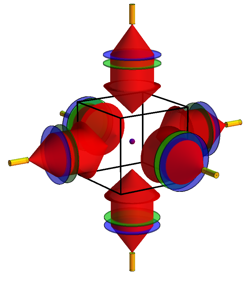
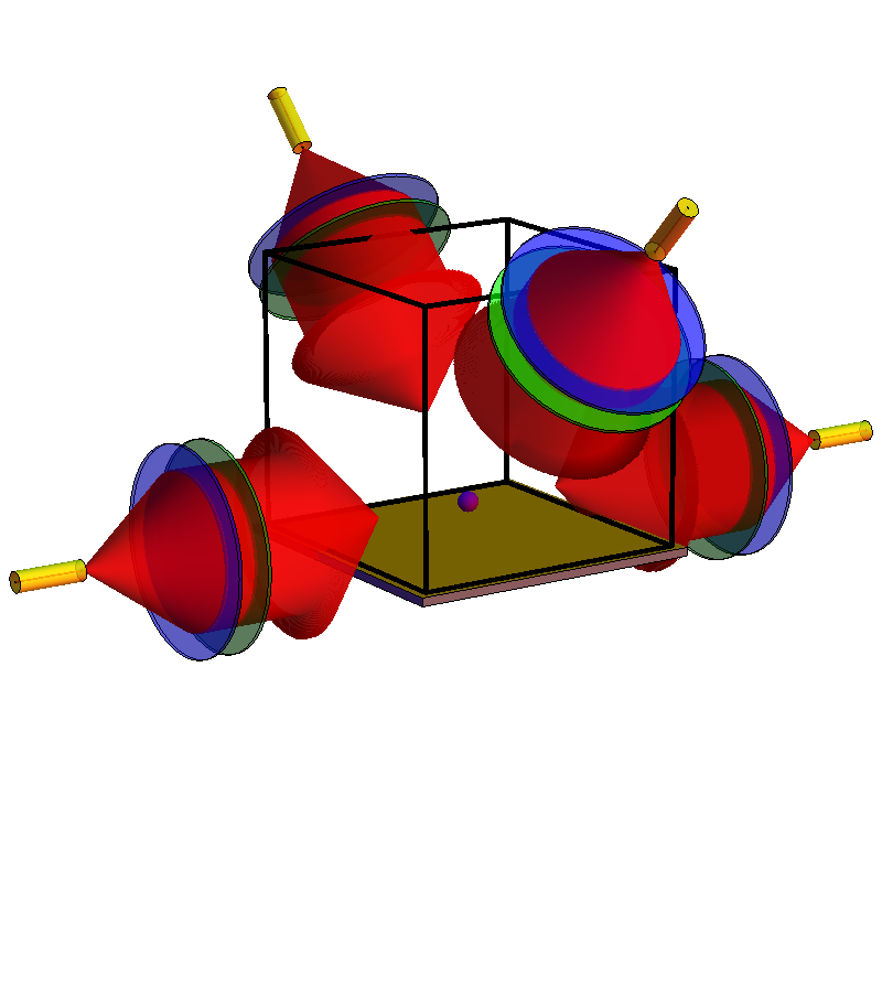
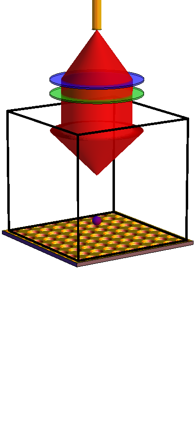
We have recently highlighted the benefits of using surface-patterned chips to make MOTs with relatively large numbers of ultracold atoms [9], compared to prior micro-fabricated magneto-optical traps (MOTs) [10, 11]. The design requires only the alignment of a single input laser beam, and extends our previous work on tetrahedral mirror [12] and grating [13] geometries, which are four-beam [15] equivalents of pyramidal MOTs [14]. Figure 1 depicts a ‘like-for-like’ graphical comparison of the optical setup in a standard 6-beam MOT (Fig. 1(a) [2, 16, 17]), a mirror MOT (Fig. 1(b) [18, 19]) and a grating MOT (GMOT, Fig. 1(c) [9]).

Here we study the atom-number characteristics of four different chip systems, and more complete details of different fabrication methods for the chips are discussed by Cotter et al. [20]. The two chip geometries we used are shown in Fig. 2. One chip style (Fig. 2(a)) comprises three one-dimensional gratings arranged in a pattern with 3-fold rotational symmetry (we used chips with periods of nm and nm). The other chip style (Fig. 2(b)) is a two-dimensional grating generated with circular regions centred in square units cells of side length nm. Hereafter the chips will be referred to as TRI15, TRI12 (Fig. 2(a)) and CIR (Fig. 2(b)). Although we have used chips TRI15 and CIR previously (chips B and C in Nshii et al. [9]), purely for number characterisation, here we present density and temperature data for these chips. Moreover, we also investigate MOTs with improved capture efficiency for the 1D structure (i.e. the new chip TRI12) and improved radiation balance for the 2D structure (chip CIR: identical to CIR but with an input beam intensity spatially sculpted with a neutral density filter – for which the rationale is given in Sec. 4).
We begin by introducing simple theoretical models for the MOT temperature (Sec. 2) and atom number (Sec. 3), then consider the amelioration of any effects caused by imbalanced radiation pressure in grating MOTs (Sec. 4). We then present the experimental data (Sec. 5), comparing and contrasting with the theoretical predictions. Finally we present ‘best of both worlds’ findings (Sec. 6) – by permitting analog temporal evolution of both MOT intensity and detuning we go beyond Nshii et al. [9] to achieve high atom numbers and sub-Doppler temperatures simultaneously using both 1D and 2D grating structures.
2 Theory: Doppler temperature
Whilst sub-Doppler cold atom temperatures can be reached in optical molasses (Sec. 6) [25, 26, 27], the conditions for atom collection in a MOT are in stark contrast to those required to reach the lowest temperatures: a MOT needs high beam intensities relative to the saturation intensity , detuning of a few natural linewidths and a magnetic gradient G/cm for a typical alkali metal vapour cell MOT with mm beam diameter. For this reason the considerably simpler Doppler theory is a good description for our MOT temperature. The standard 3D Doppler result for a sample of atoms uniformly and isotopropically illuminated in three dimensions by light of total intensity with corresponding saturation parameter and detuning [21] is:
| (1) |
where In our 87Rb experiment we cool using the rubidium D2 transition which has a natural linewidth MHz. The standard Doppler temperature minimum in the limit of low intensity and detuning is , i.e. K for rubidium, with the more general lowest temperature minimised at a detuning . Throughout this paper, for consistency, we use the saturation intensity averaged over all polarisations and magnetic sub-levels mW/cm2 – however we note that using the stretched state saturation intensity mW/cm2 for the theoretical temperature of Eq. (1) leads to much better agreement with our experimentally measured temperatures (Sec. 5).
Although the velocity distribution in a magneto-optical trap is Gaussian, the system is by no means in thermal equilibrium in the usual sense, with the typical light scattering rate from atoms vastly larger than the interatomic elastic collision rate. The final ‘temperature’ in a given direction is given by the balance between the heating (cf. diffusion coefficient and light scattering rate) and the velocity damping constant . In our system the effective temperature parallel to and perpendicular to the grating are therefore expected to be different.
For our gratings if the incident beam has a spatially uniform intensity and wavevector , for balanced optical pressure from diffracted orders each should ideally carry an intensity of with . The wavevectors of the diffracted beams are , where is the angle the diffracted orders make to the grating normal ( cf. [12, 13]). The total intensity is therefore with each beam of intensity contributing a relative intensity-dependent heating proportional to its intensity along the beam direction due to absorption, and an equal associated heating rate due to spontaneous emission. The heating from spontaneous emission is assumed for simplicity to be isotropic, with the heating rate for light with a wavevector proportional to in the and dimensions, for a scattering rate
| (2) |
Assuming dipolar (as opposed to isotropic) spontaneous emission from a circularly polarised atom adds complexity and does not significantly alter the predicted temperatures. The heating due to absorption is apportioned in the three spatial dimensions. The total heating rate near zero velocity in each dimension is thus:
| (3) |
which simplifies to
| (4) |
In balanced laser cooling the relative damping constants can be determined by the Taylor expansion of the total force equation about The damping constants in the directions ( parallel to the grating) and direction ( perpendicular to the grating) are thus given by [12]:
| (5) |
is the damping force in a standard 6-beam MOT. The temperature in each dimension can then be determined as proportional to the ratio of the diffusion D (Eq. (4)) to the damping (Eq. (5)):
| (6) |
which reduces to the standard isotropic temperature when Note this temperature only depends on the grating diffraction angle and not on the number of diffracted orders
The temperatures obtained experimentally (Sec. 5) do not reflect the theoretical temperature disparity in the directions parallel and perpendicular to the grating. The model above only includes forces due to absorption of light directly from the laser beams, however for MOTs with larger atom number and light scattering rate (like in our experiment), there will be a significant contribution to the forces in the MOT due to the repulsion from closely packed atoms with inter-particle spacing due to absorption of spontaneously emitted light from neighbouring atoms [28, 29, 30, 31]. These forces effectively mix the energies across dimensions, creating a more uniform temperature distribution. The theoretical temperature we use in both dimensions is therefore , which agrees surprisingly well with experimental values given the simplicity of the model.
For completeness and to determine theoretical MOT density, one can also derive the spring constant of the trap, expanding the total force F, but this time relative to position. The dependencies of the damping constants are the same as derived by Vangeleyn et al. in [12]. The damping therefore reduces to an isotropic () of the standard 6-beam MOT radial (axial) values, if the GMOT has and laser beams of the same intensity as the standard MOT. Under these conditions the GMOT should be spatially isotropic – it will have equal rms cloud radii as a standard MOT in both directions parallel to the grating, but twice the standard MOT extent in the direction perpendicular to the grating. An important caution against using this Doppler spring constant to determine density, however, is that the experimental spring constant of a trap is notoriously difficult to determine, and the reradiative forces [28, 29, 30, 31] discussed in the previous paragraph make simple models of the effective spring constant considerably more difficult.
3 Theory: Doppler atom number
In order to predict the number of atoms in the MOT, we use the standard method of Lindquist et al. [16]: treat the MOT as a spherical target region with radius and cross-section , then find the flux of atoms incident on the target, with speeds less than the capture velocity of the MOT slowing region. In the ideal case of a rubidium-dominated vapour both loading and loss mechanisms are proportional to atomic density, which is therefore irrelevant for calculating atom number. It is necessary to know the collisional cross section of cold atoms as seen by hot atoms, which for rubidium is m2 [32] (similar to caesium [16]). We make the assumption of a 1D optical molasses from two counter-propagating laser beams. The total acceleration is modified by a prefactor to allow for geometric effects:
| (7) |
By rearranging one arrives at an equation of the form , where is a quartic polynomial in and is a constant. This equation can then be integrated to analytically determine . The integration constant is chosen such that . Setting (atoms are stopped over a distance of twice the MOT radius) and subsequently inverting gives , the capture velocity. The total steady-state number of atoms in the MOT is then [16]:
| (8) |
where is a thermal velocity in the (hot) background vapour.
We note that the saturation intensity features in the theoretical temperature and both theoretical and experimental atom number, and we therefore consistently use the saturation intensity averaged over all polarisations and magnetic sub-levels mW/cm2, which is valid for small detunings [23, 24]. There are, however, arguments for using a value closer to the stretched state saturation intensity mW/cm2 [22]. We used this value in our previous work on atom number [9] as a precaution to prevent over-counting the atom number, although for high levels of saturation the effect of changing on experimental atom number is negligible.
4 Theory: Non-uniform beam intensity
In the theory so far we have assumed a spatially uniform incident laser intensity. However, real propagating laser beams tend to have Gaussian spatial intensity profiles. If such intensity distributions are apertured, or their intensity is spatially modified in other respects, as long as the modifications occur on large (centimetre size) beams, diffraction effects can be neglected. While various refractive beam shapers which transform Gaussian beams into flat-top intensity beams are available on the market, these tend to be expensive (albeit power efficient) and designed for relatively small output beam diameters. Spatially shaping a Gaussian beam with radial profile using an apodizing filter of outer radius with a neutral density leads to a uniform beam intensity, with reduced intensity across the beam. The relative power in the beam is then which has a maximum of when the aperture radius is – i.e. even under optimal conditions it is a fairly lossy solution.
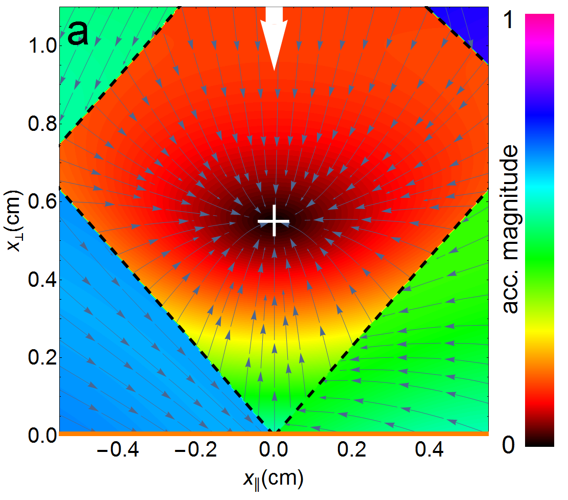
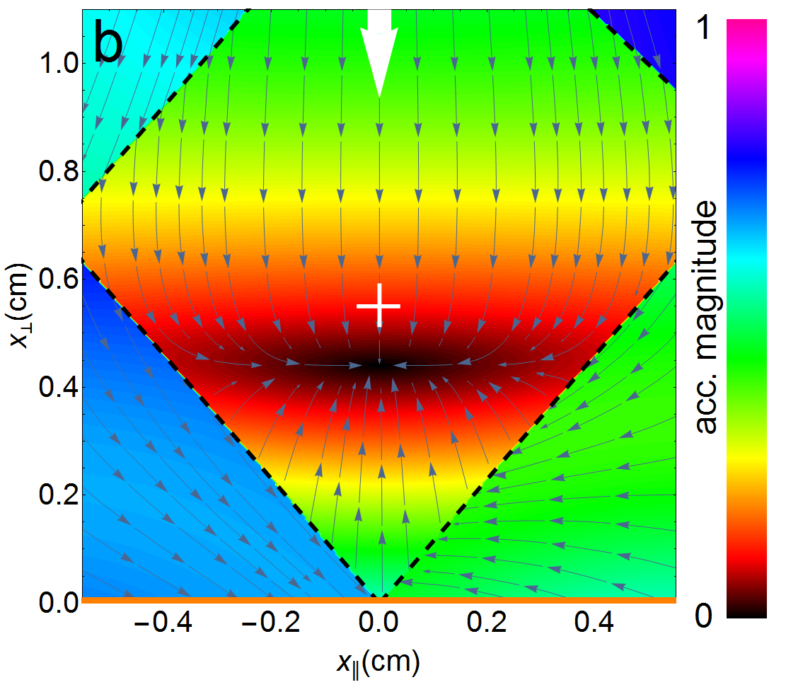
To determine the effect of Gaussian intensity profiles, we fully integrate the acceleration from a MOT with a single input beam and 3 diffracted orders at diffraction angle , just like Chip TRI12 (Fig. 3). We assume similar parameters to the MOT experiment – a Gaussian input trap beam with intensity mW/cm2 and detuning apertured to a mm radius and a magnetic quadrupole with axial gradient G/cm. In situations where the beam intensity is spatially uniform (Fig. 3(a)) the radiation pressure balance is uniform throughout the beam-overlap volume. However, with a Gaussian beam intensity profile (Fig. 3(b)), the diffracted orders at the MOT location originate from lower and lower intensity regions of the Gaussian beam as the MOT position is raised from the grating surface. This means that the MOT is pushed downwards more, relative to the magnetic quadrupole centre, as the MOT is raised above the grating surface. Moreover, there is a marked change in the relative trapping and damping constants: in Fig. 3(a) and in Fig. 3(b) (compared to the isotropic values of for and uniform intensity).
The case of uniform intensity is preferable, as long as one has optimal diffraction efficiency in the gratings, as then the MOT and molasses properties do not depend on MOT position. However, if one uses Gaussian beams and the diffraction efficiency is too high, one can compensate by raising the MOT position to a location where optical forces are balanced and suitable for sub-Doppler cooling. In Sections 5 and 6 with chip CIR we show how locally shaping the input beam intensity can dramatically improve both MOT and molasses performance.
5 Experiment
The experimental conditions were very similar to those detailed in the Methods section of Nshii et al. [9]. One major difference is that we now have analogue as opposed to binary intensity control, using an acousto-optic modulator (AOM) after our tapered amplifier prior to fiber-coupling. After the MOT reached steady-state atom number, the atoms were ballistically released for or ms, and Gaussian fits were used to extrapolate cloud rms radii and thereby MOT temperatures. To build up statistics each drop time was iterated five times. For intensities above and below mW/cm2 the fluorescent imaging exposure times were s and s, respectively.
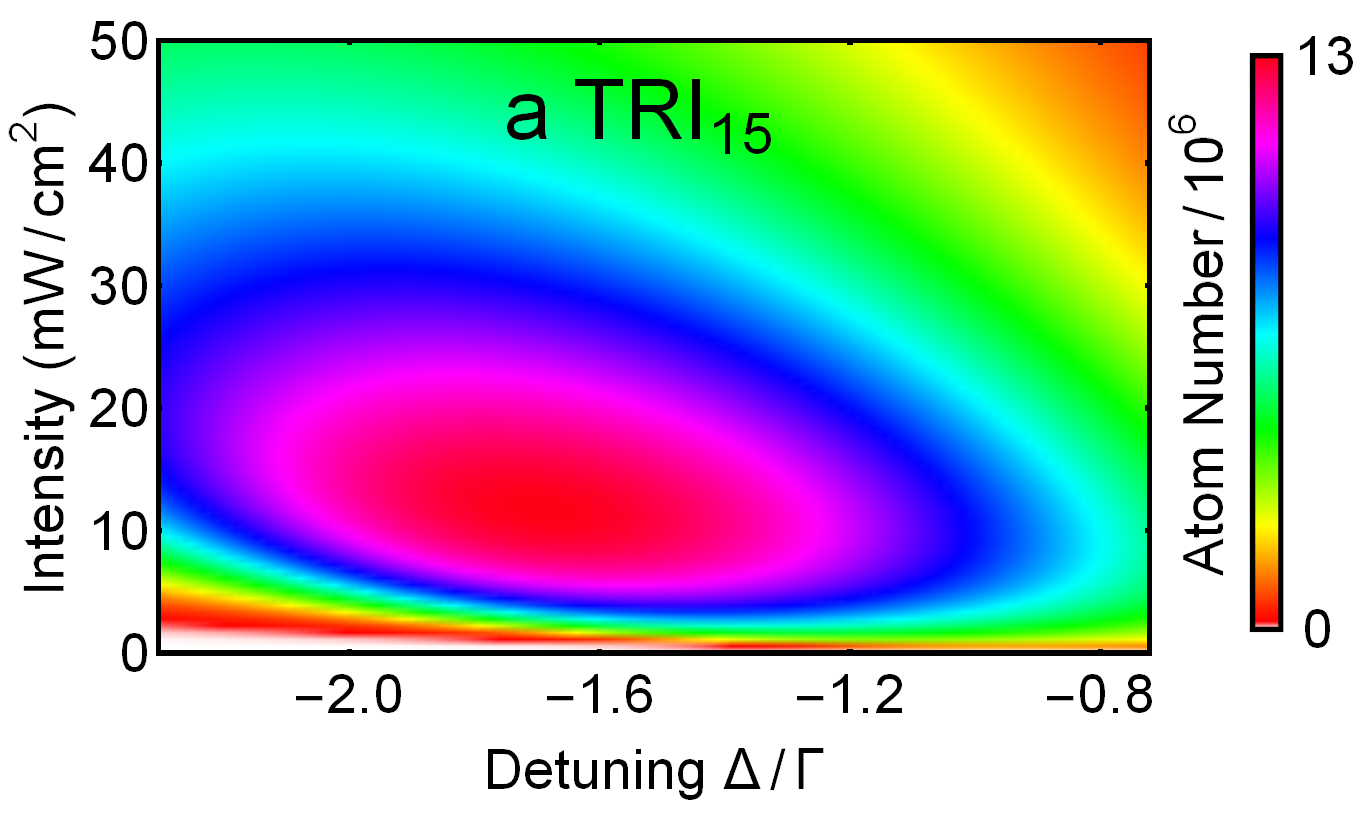
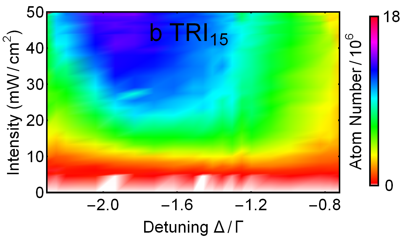
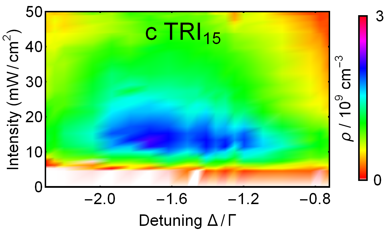
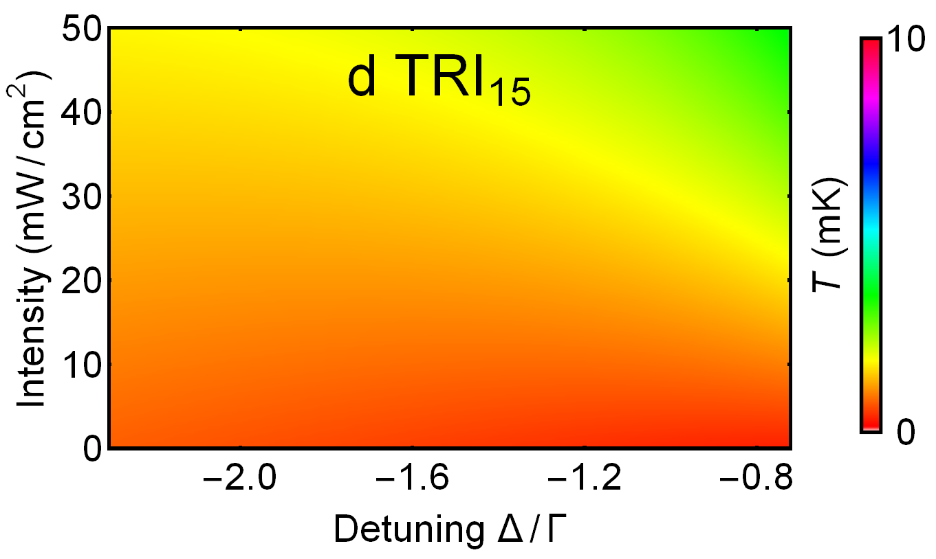
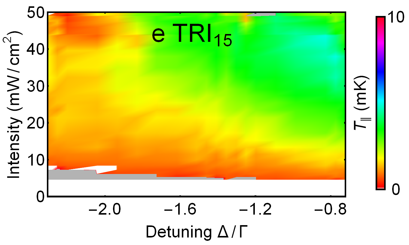
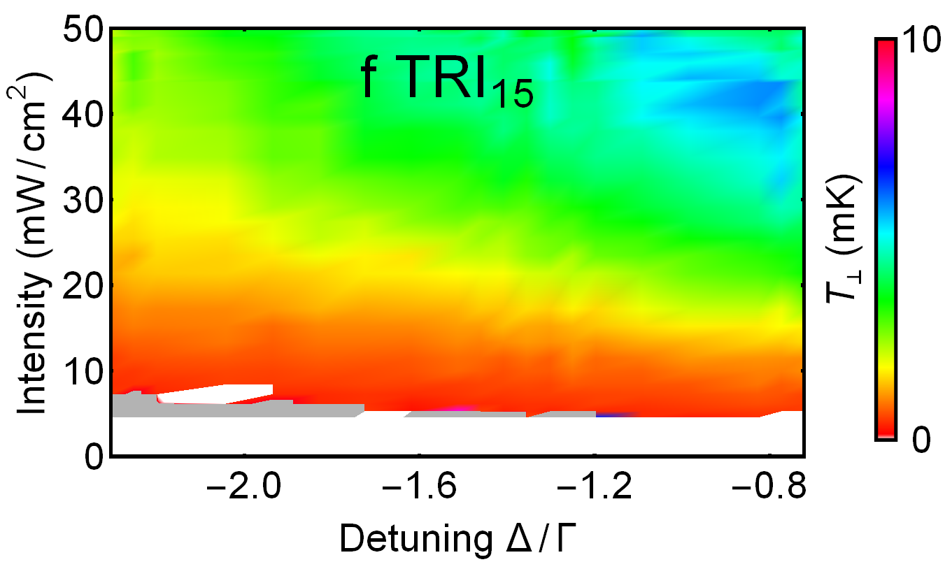
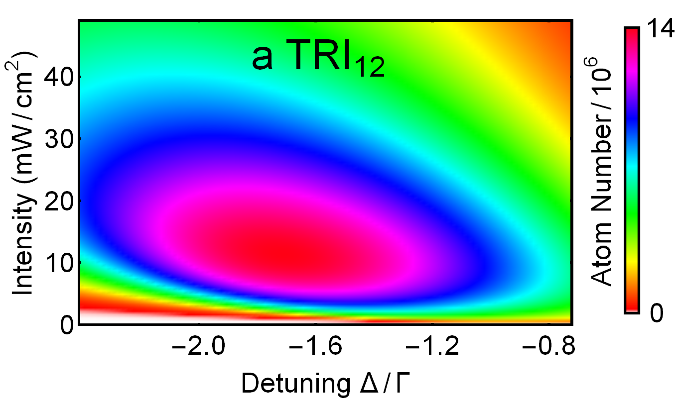
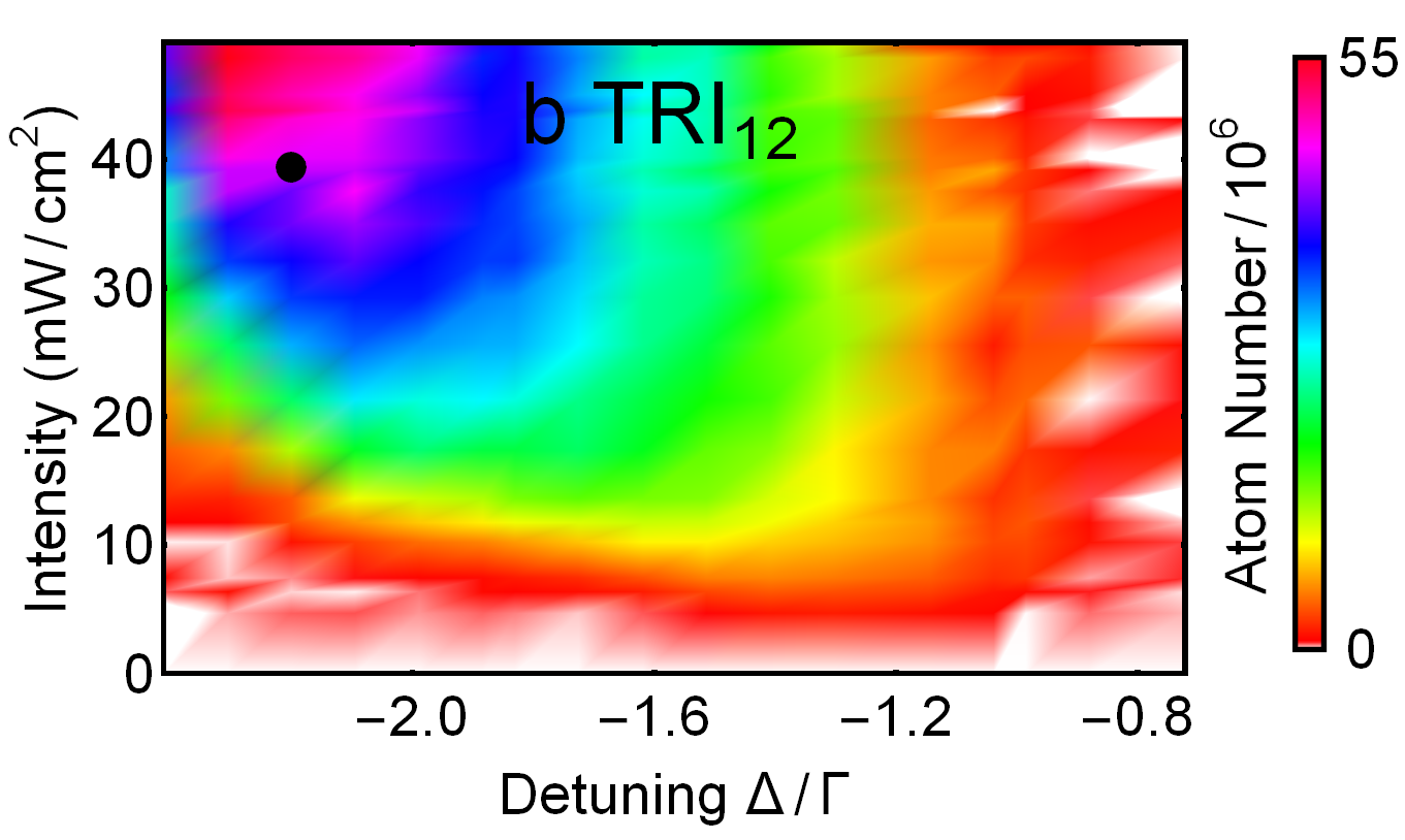
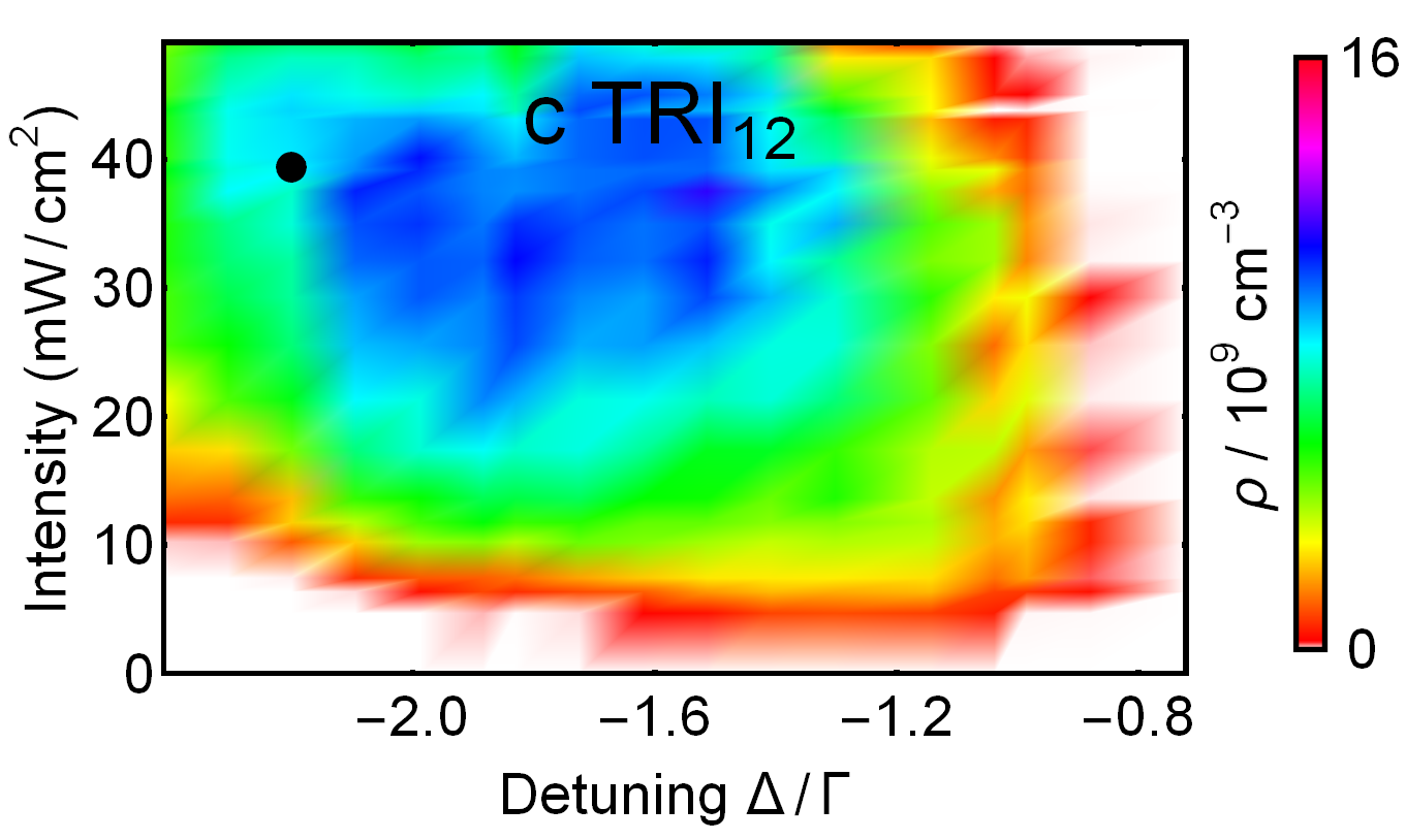
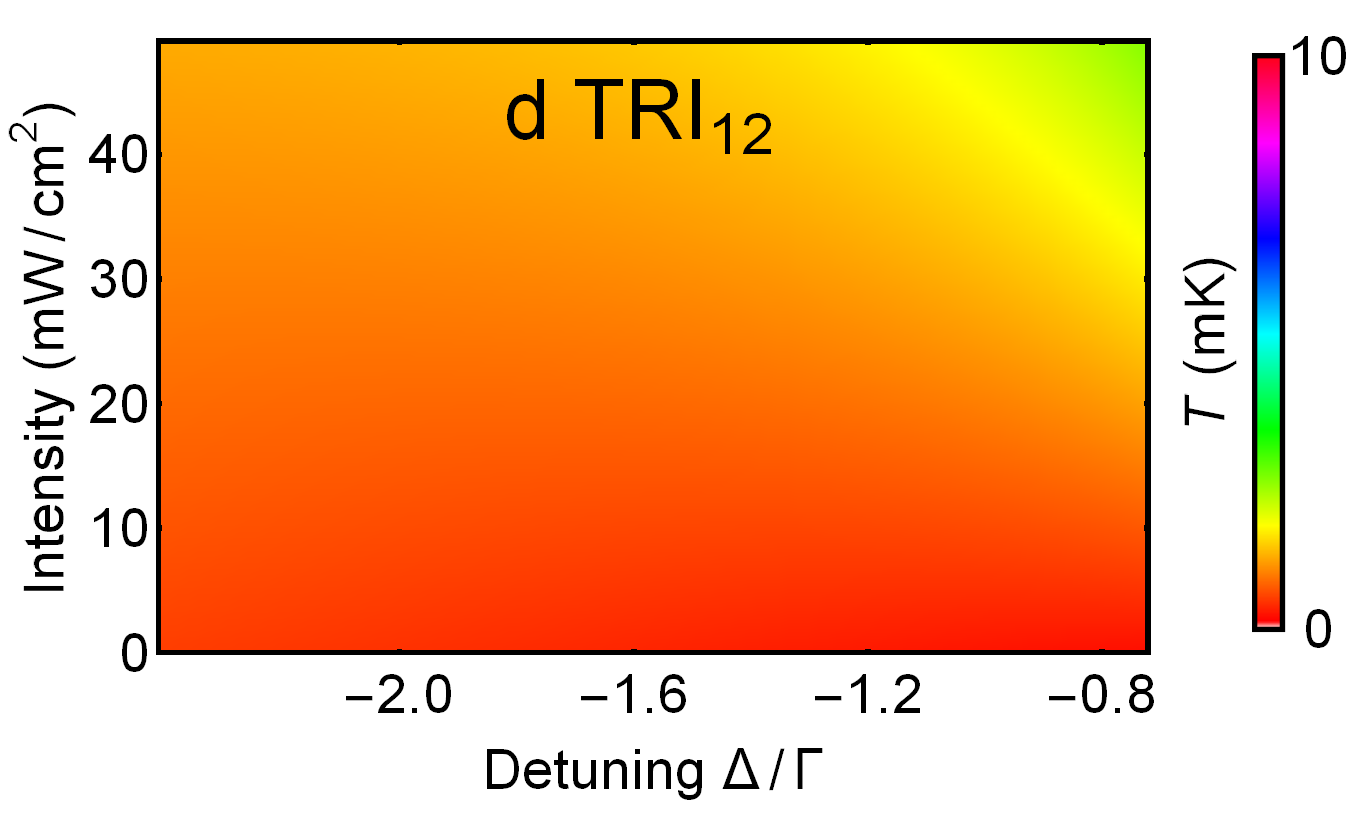
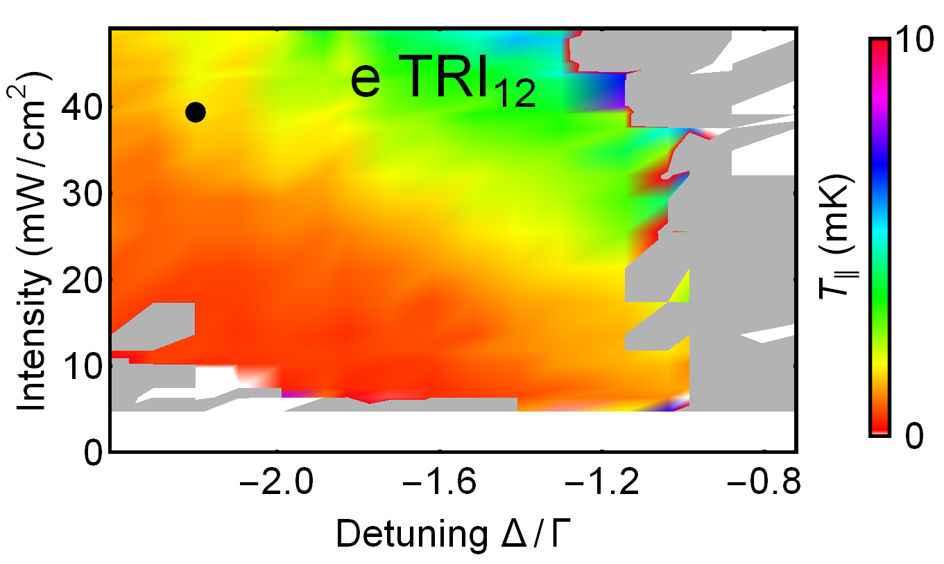
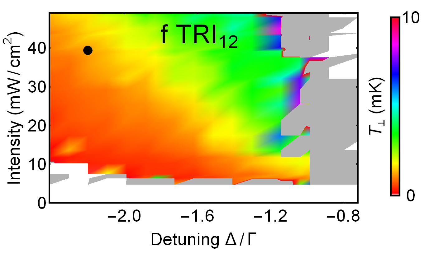
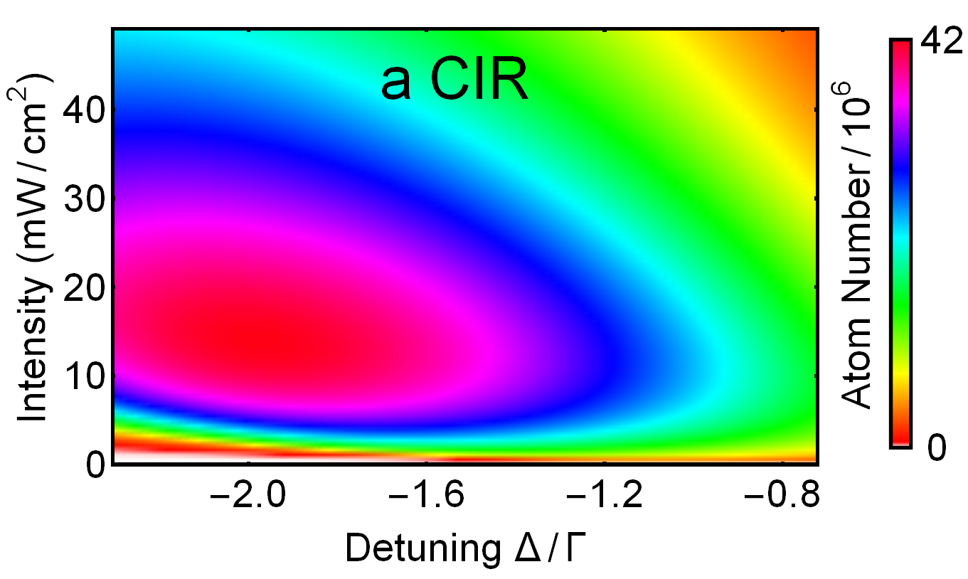
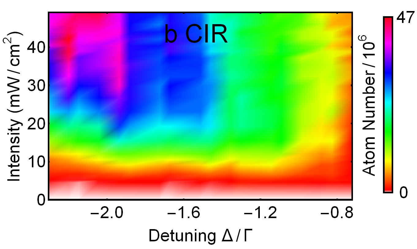
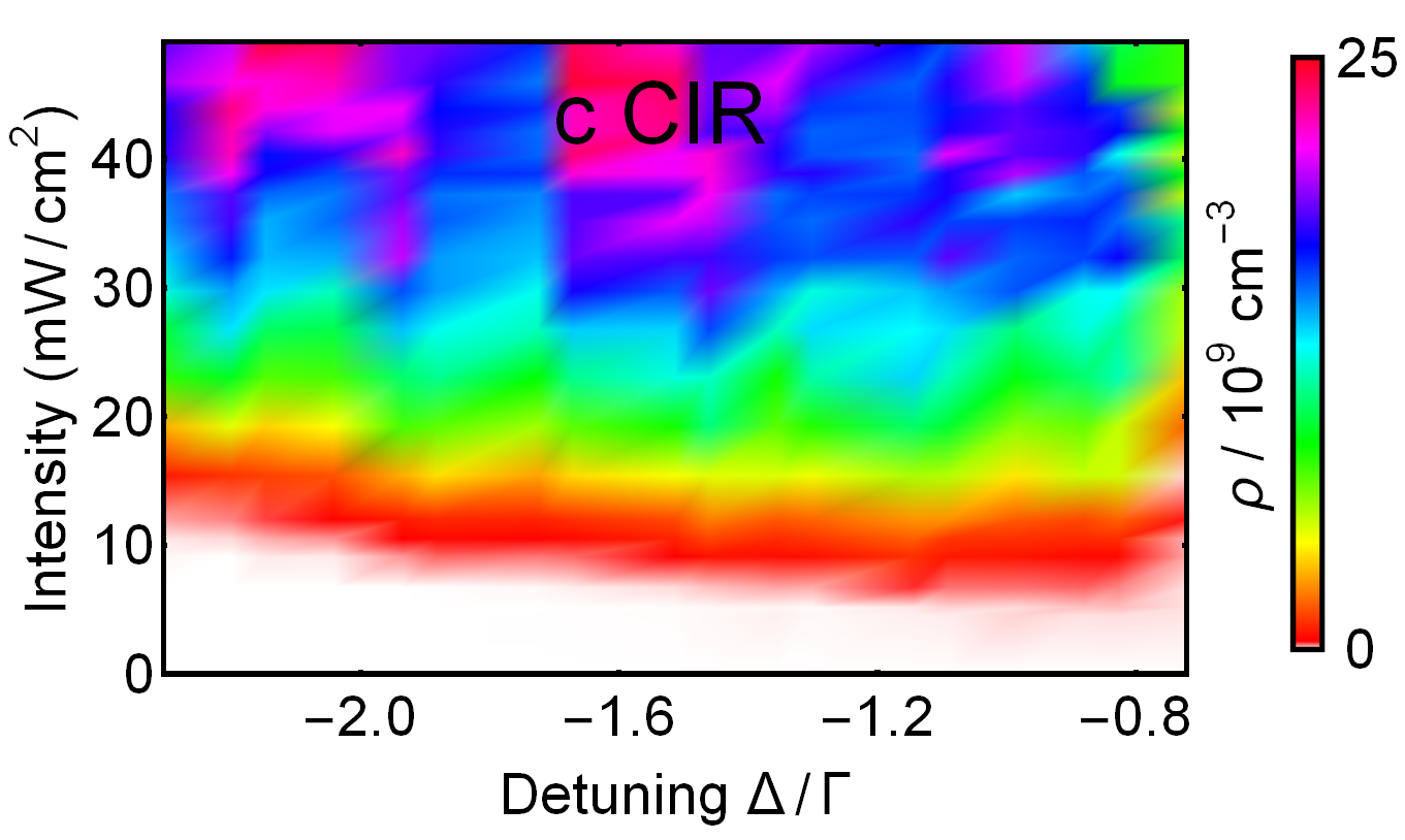
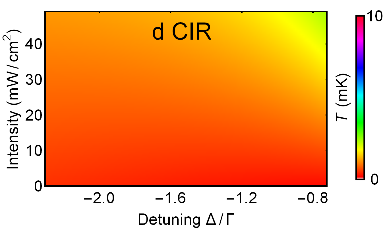
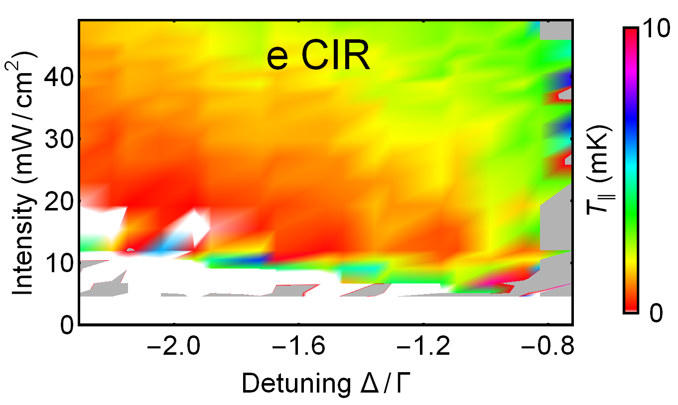
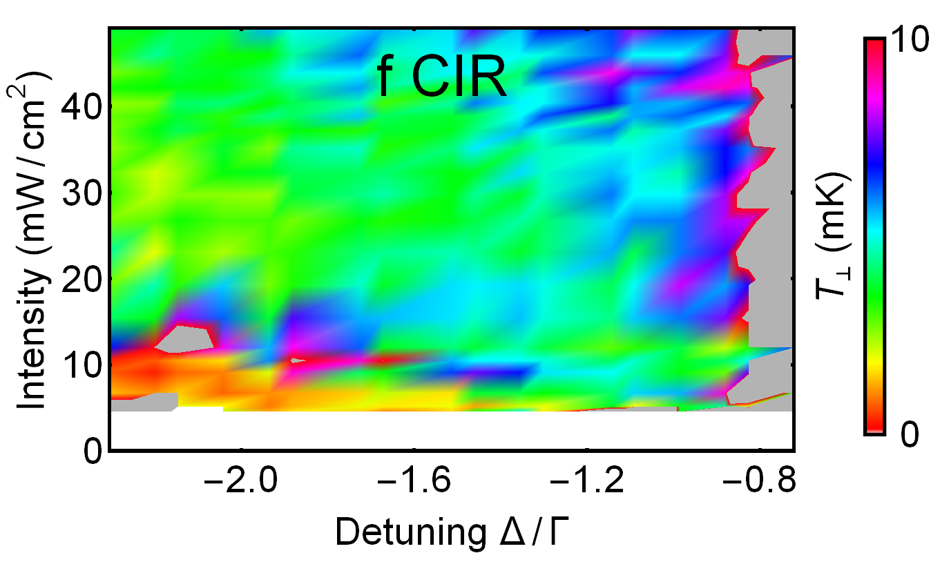
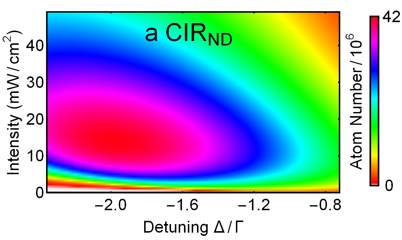
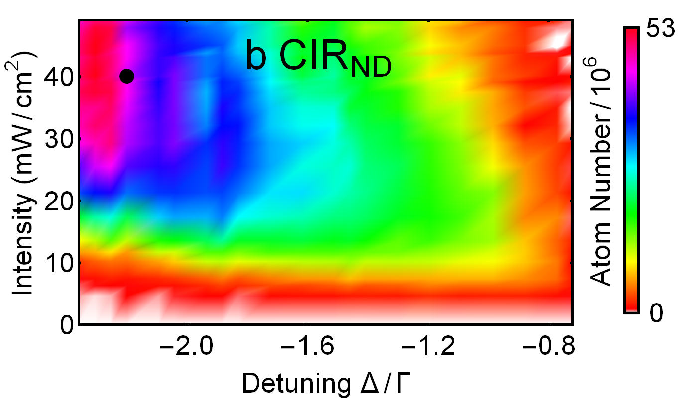
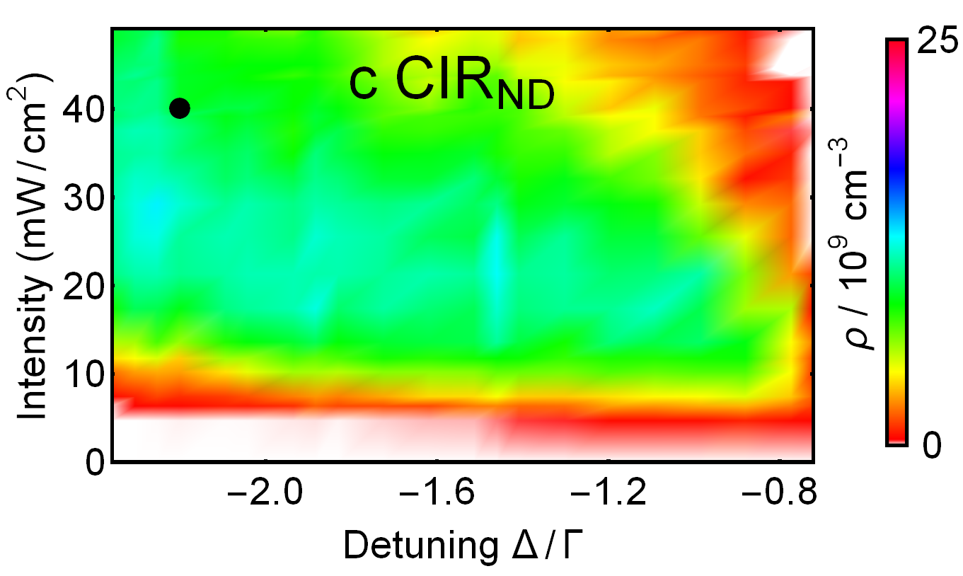
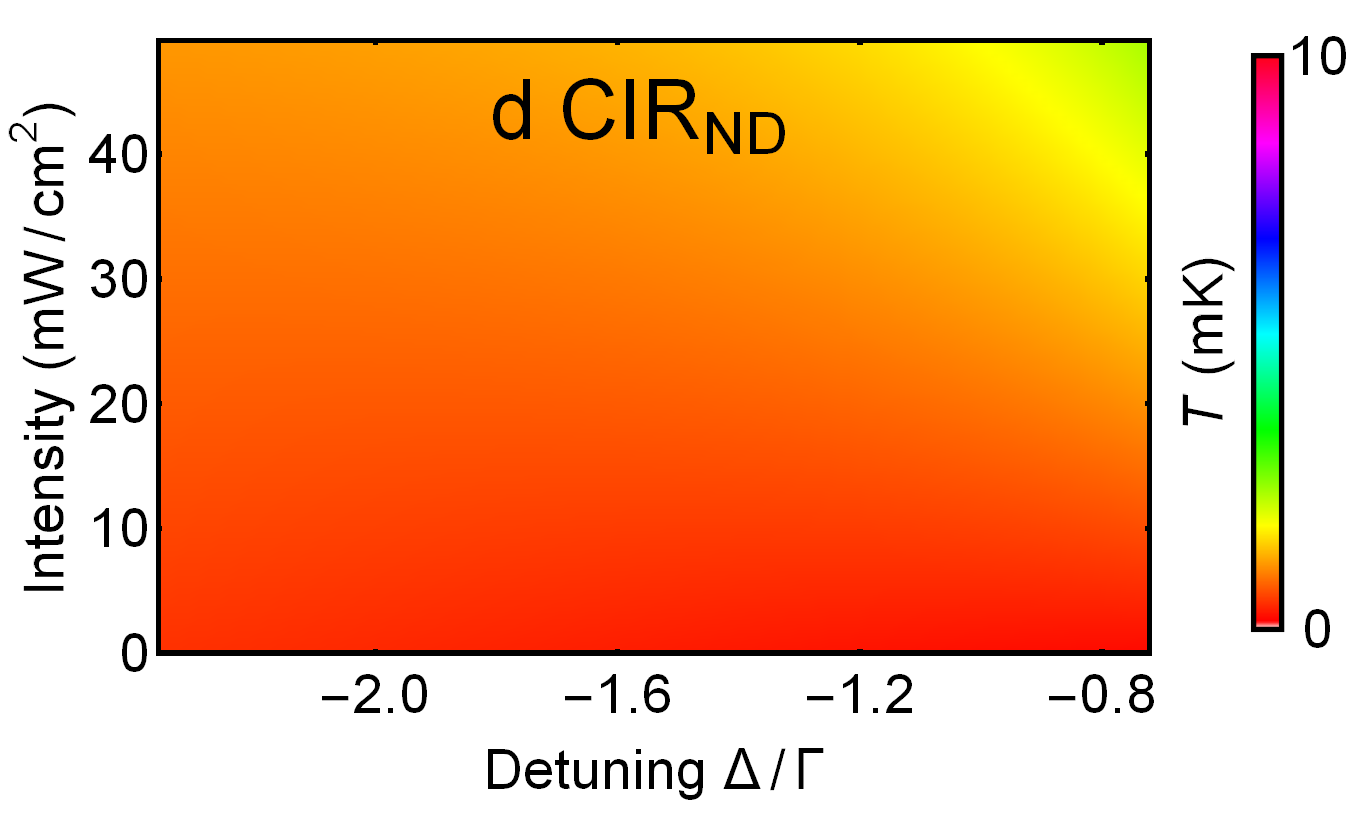
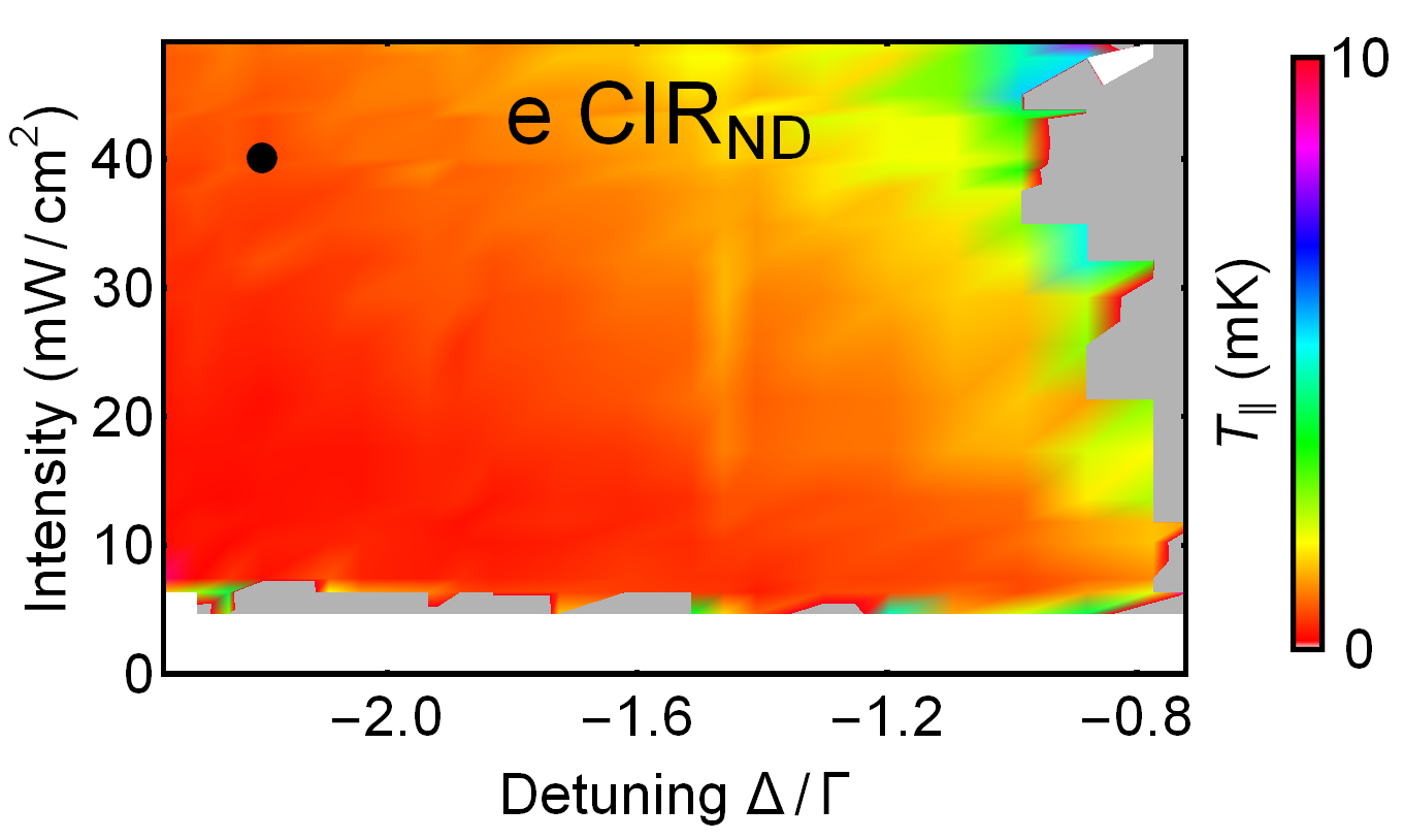
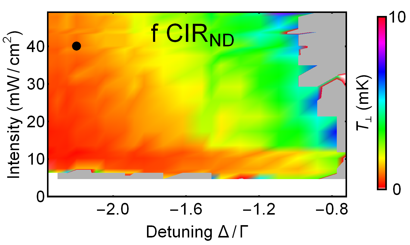
Figures 4 (Chips TRI15 and TRI12) and 5 (Chips CIR and CIR) illustrate the intensity- and detuning-dependence of a variety of MOT parameters: theoretical atom number (a), experimental MOT atomic number (b) and spatial density (c) as well as the theoretical Doppler temperature (d) with the temperatures experimentally measured in the directions both parallel (e) and perpendicular (f) to the grating. Note that the theoretical atom number saturates at about three times lower intensity than that observed experimentally – we seem to need three times more laser power experimentally than we would theoretically expect. This discrepancy may be considered relatively minor given the very simple nature of the theoretical model, however we believe further investigation, and full comparison to a standard 6-beam MOT may still be warranted.
In prior measurements of on Chip CIR (Fig. 5(f) CIR) there was an even larger discrepancy with theory (very high experimental temperatures) due to imbalanced optical force during the fluorescence imaging. This was determined via the noticeable centre-of-mass velocity accrued in the direction perpendicular to the grating during time-of-flight. In all the new data for Figs. 4 and 5 any imbalanced radiation pressure (mainly for Fig. 5) was balanced using a non-zero magnetic field oriented perpendicular to the grating.
Note the significant increase in atom number () and density (), with lower atomic temperature on chip TRI12 compared to chip TRI15 – in future we intend to test gratings with even smaller period (larger diffraction angle) to determine if this trend continues.
6 Experiment: best of both worlds
For many metrological experiments, such as atomic clock measurements, the precision achieved strongly depends upon the temperature and total population of the atomic ensemble. Hence, an understanding of the final number of atoms that can be brought from the MOT stage to ultracold temperatures provides a good indication of the full capability of the GMOT. In Nshii et al. [9] we effectively had only binary control of the intensity – this meant we could either get a large number of atoms on Chip CIR with high intensity, or good optical molasses on chip TRI15 with lower intensity light (and a correspondingly small number of atoms loaded in the MOT).
After analysis of the results presented in Section 5, the most suitable gratings for MOT number and temperature are Chip CIR and TRI12. To study the number of atoms that could be brought to sub-Doppler temperatures, a MOT of intensity mW/cm2 and detuning of (initial MOT indicated by black dots in experimental Figs. 4 TRI12 and 5 CIR) was transferred into optical molasses. The molasses consisted of turning off trapping magnetic fields, whilst using a two-step frequency jump of and , each of duration ms.


Under these conditions, Chip CIR brought atoms down to a 3D average temperature of 50 K (Fig. 6(a)). Chip TRI12 used the same settings with the exception that the molasses intensity was reduced to mW/cm2 – bringing 2.5 atoms down to a 3D average temperature of K (Fig. 6(b)). Both temperatures are similar to those achieved by Nshii et al. in [9] (with TRI15), but with an order of magnitude more atoms after molasses ( in [9], due to the lack of intensity control discussed above). Temperature is determined by fitting to the data, where is the standard deviation of the Gaussian fit to the atomic cloud spatial distribution, is the mass of an 87Rb atom, is Boltzmann’s constant and is the initial standard deviation of the cloud.
7 Interpretation and conclusions
Both the experimental MOT atom number and cloud temperature demonstrate surprisingly good agreement with theory, given the simplicity of the theoretical models employed.
We note that higher densities are achieved on Chip CIR and CIR, largely due to the larger diffraction angle , with higher associated damping and trapping coefficients. There is a dramatic density improvement with TRI over TRI and this trend may continue with higher values of toward the tetrahedral configuration , with the caveat that the capture volume and grating diffraction efficiency will decrease. In Doppler theory the cloud size scales as however we note from the relatively constant experimental MOT density for a variety of detunings and intensities that we are reaching sufficient atom numbers to likely be entering the MOT ‘constant density regime’ where reradiation forces become more important than restoring forces [28, 29, 30, 31].
In terms of the temperature, significant sub-Doppler effects are not present, however we note that one would only expect sub-Doppler cooling under conditions of low intensity and large negative detunings, where we have insufficient data coverage to draw any further conclusions. The atom number is sufficiently large that effects where the MOT temperature is expected to increase with atom number might also become evident [33, 34].
Compact quantum measurement devices are a burgeoning area [35, 36, 37], with grating technologies providing a new way to optically simplify transportable ultracold atom experiments. In future we hope to investigate the effect of grating diffraction angle on both grating optical properties [38] and cooling performance. The current work could also be extended from investigating MOTs into sub-Doppler optical molasses regimes [39], preparing the path for future studies of on-chip Bose-Einstein condensates and extremely stable optical lattices [9].
Acknowledgments
We gratefully acknowledge support from ESA under contract 4000110231/13/NL/PA and the UK EPSRC. PFG acknowledges the generous support of the Royal Society of Edinburgh.