Algorithmic Cooling in Liquid State NMR
Abstract
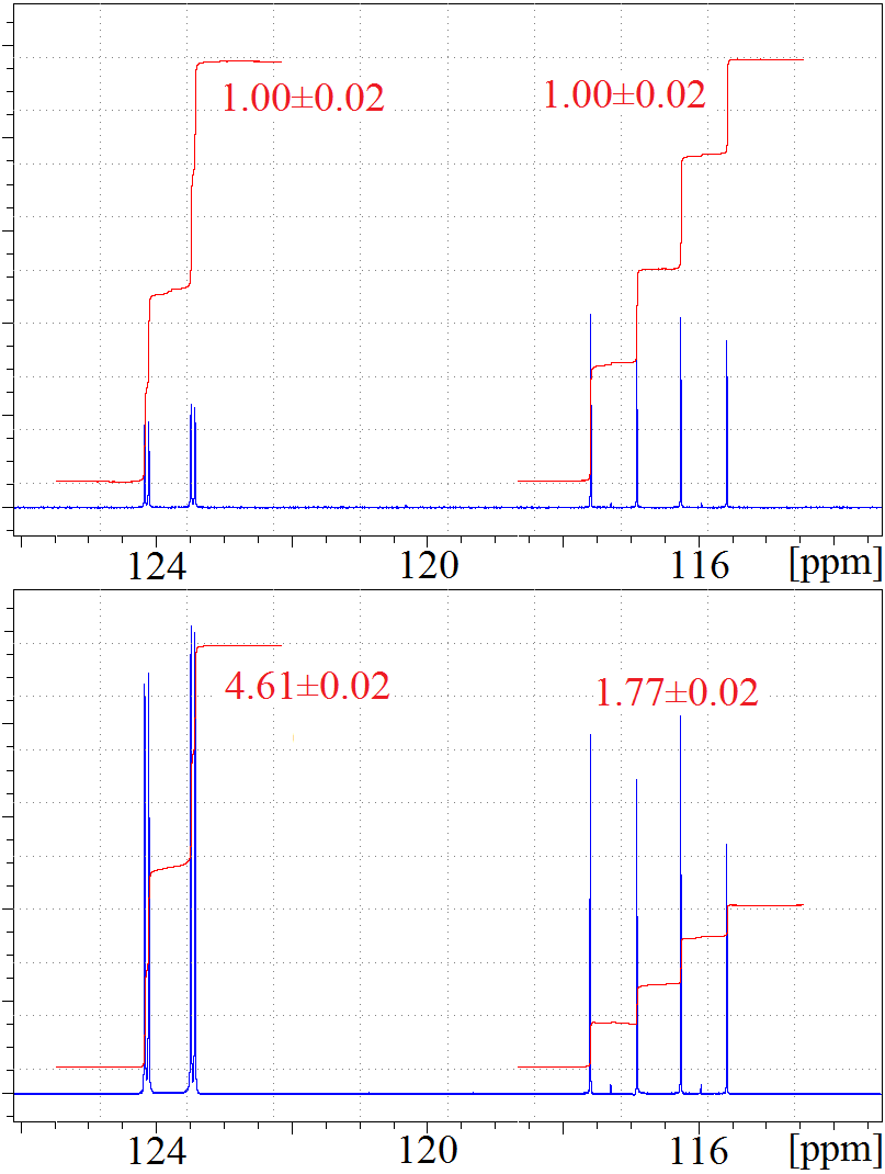
Algorithmic cooling is a method that employs thermalization to increase qubit purification level, namely it reduces the qubit-system’s entropy. We utilized gradient ascent pulse engineering (GRAPE), an optimal control algorithm, to implement algorithmic cooling in liquid state nuclear magnetic resonance. Various cooling algorithms were applied onto the three qubits of 13C2-trichloroethylene, cooling the system beyond Shannon’s entropy bound in several different ways. In particular, in one experiment a carbon qubit was cooled by a factor of 4.61. This work is a step towards potentially integrating tools of NMR quantum computing into in vivo magnetic resonance spectroscopy.
I Introduction
The quantum computational model permits algorithms that provide significant — and sometimes even exponential — speed-up over any known classical counterpart Simon (1994); Shor (1997); Harrow et al. (2009). A rather different scope of that model is to enable improved quantum technologies, e.g. quantum repeaters for communicating secure data over longer distances Briegel et al. (1998). Algorithmic cooling, experimentally implemented in this work, is a method that might contribute to both scopes. On the one hand, it was originally suggested as a method for increasing the qubits’ purification level Boykin et al. (2002); Fernandez et al. (2004); Schulman et al. (2005); Raeisi and Mosca (2015); Rodriguez-Briones and Laflamme (2015); Park et al. (2015), as qubits in a highly pure state are required both for initialization and for fault tolerant Knill et al. (1998); Aharonov and Ben-Or (1997) quantum computing. On the other hand, the suggested novel usage of data compression may potentially be found useful for increasing the signal to noise ratio of liquid-state NMR and in vivo magnetic resonance spectroscopy Fernandez et al. (2004); Mor et al. (2005); Elias et al. (2011a).
Nuclear magnetic resonance quantum computing (NMR-QC) Cory et al. (1996, 2000); Glaser (2001); Vandersypen and Chuang (2005); Jones (2011) commonly uses spin nuclei (hereinafter spins) of molecules as qubits. Compared to other implementations of small quantum computing devices, liquid-state NMR has an advantage of relatively easy realization of quantum gates by applying RF fields and utilizing spin-spin interactions. However, NMR-QC also has some disadvantages due to working with an ensemble of spins in a mixed state Gershenfeld and Chuang (1997); Boykin et al. (2010), e.g. it is not scalable. Algorithmic cooling, in theory, resolves that problem Boykin et al. (2002); Fernandez et al. (2004); Schulman et al. (2005).
The thermal energy at room temperature is much higher than the magnetic potential energy of nuclear spins even in the most advanced NMR devices. Therefore, at equilibrium, the qubit ensemble is in a highly mixed state - the probability difference between the “up” and “down” states (hereinafter the polarization, denoted as ) is very small. At thermal equilibrium
| (1) |
Here is the gyromagnetic ratio of the spin, is the intensity of the magnetic field, is the Boltzmann constant and is the bath temperature. When outside of equilibrium, spins with higher polarization than their thermal equilibrium polarization are considered “cool”, and we can use Eq. 1 to define the spin temperature as .
Upper bounds on spin cooling (i.e. on polarization enhancement) can be derived by interpreting the spin state in terms of information theory Cover and Thomas (2006). The information content () of the spin was defined using the conventional notion of Shannon entropy . The relation between a single spin’s polarization and is given by the following equation Brassard et al. (2005); Elias et al. (2007)
| (2) |
The information content of a spin system is invariant to reversible operations, and therefore bounds the maximal a single spin can reach by lossless manipulations, such as quantum gates. This entropy bound, also often called Shannon’s bound, limits the maximal polarization of a single spin, given an initial thermal state of the spin system.
In our spin system, 13C2-trichloroethylene (TCE, see Figure 1), consisting of a proton and two 13C, the at thermal equilibrium is:
| (3) |
Shannon’s bound dictates that a single spin cannot hold more than the equilibrium information content of the entire spin system:
| (4) |
For convenience, we approximate , and then , and .
Algorithmic Cooling (AC) of spins counter-intuitively utilizes the heat bath, that decays polarizations to thermal equilibrium, to cool spins beyond Shannon’s bound. AC requires a spin system where some spins, called reset spins, thermalize significantly faster than other spins, called computation spins. Reversible polarization compression (hereinafter compression) is applied to the spin system, transferring some of the computation spins’ entropy to the reset spins, which quickly lose some of it to the environment. The process can be repeated, converging the system to a stable trajectory (limit-cycle) in the thermodynamic diagram. The efficiency and the cooling limit of AC are (ideally) dependent on the unitary restriction of processes between reset steps, and on the ratio between the relaxation times of the cooled spins and the reset spins.
Various cooling algorithms were developed, following the basic principle presented in Boykin et al. (2002). For example, in a three qubit system with uniform equilibrium polarization , the initial information content is , the maximum polarization of a single spin that can be reached using unitary transformations Sørensen (1989); Schulman and Vazirani (1999), is , and Shannon’s bound for the maximal polarization of a single spin is . But if one spin has a much shorter thermalization time than the other spins, it will reset while the others retain most of their polarization, so that the entire spin system is cooled. Ideally, iterating the compression process twice leads to a bias of , bypassing the result obtained by unitary transformations and even bypassing Shannon’s bound Fernandez et al. (2004). Repeating the process while assuming infinite relaxation time ratios allows enhancing the polarization of one spin asymptotically to 2 Fernandez (2003). Algorithms applying these processes to qubits ideally cool exponentially beyond the unitary cooling Boykin et al. (2002); Fernandez et al. (2004), and can be practicable or optimal, see Fernandez et al. (2004); Schulman et al. (2005); Elias et al. (2006, 2007); Schulman et al. (2007); Elias et al. (2011b).
In TCE, the proton reset spin has higher equilibrium polarization than C1 and C2, the 13C computation spins. In such scenarios, even a special case — AC without compression (called heat bath cooling Brassard et al. (2005); Elias et al. (2011a)), can cool the spin system beyond Shannon’s bound. This can be done by applying a polarization transfer Morris and Freeman (1979) from the proton to C1, or alternatively, by swapping the two polarizations via a polarization exchange (PE) gate, and waiting for the proton to regain some of its polarization (while the carbon is still cool). A successive PE from the proton to C2 followed by another waiting period yields polarization of approximately on all three spins, in units of carbon equilibrium polarization. If the relaxation time ratio is sufficiently large, and all gates are perfect then , far above the initial approximate value of . Further cooling can be achieved using compression.
In practice, heat bath cooling of TCE Brassard et al. (2005), yielded polarizations for C1, C2 and the proton respectively, well below the ideal . Yet, the resulting total is (), which is beyond (and statistically significant) the experimental initial (of ) at equilibrium, hence showing for the first time that the Shannon bound can be experimentally bypassed. Heat bath cooling on two amino-acids Elias et al. (2011a) also successfully bypassed Shannon’s bound later on. On the other front, experimental work, cooling solely by compression was done by Sørensen Sørensen (1989) on methylene chloride, and by Chang, Vandersypen and Steffen Chang et al. (2001) on three fluorines in C2F3Br. Full AC Baugh et al. (2005) and multi-cycle AC Ryan et al. (2008) using solid-state NMR was successfully done at the University of Waterloo.
II Materials and methods
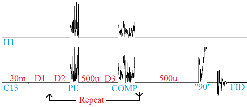
In order to implement AC and multiple-cycle AC on liquid-state TCE we utilized (following Ryan et al. (2008)) Gradient Ascent Pulse Engineering (GRAPE) Khaneja et al. (2005), an optimal control algorithm, to generate high fidelity pulses for obtaining the compression gate and the PE gate Atia et al. (2014). Here we present various algorithms for cooling liquid TCE. Process 1 (see Figure 2), aimed to maximize , is as follows:
-
1.
Wait for duration D2 (H regains polarization)
-
2.
PE(H C2)
-
3.
Wait for duration D3 (H regains polarization)
-
4.
Compression of C1,C2,H onto C1.
-
5.
Return to step 1, unless C1 is saturated.
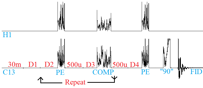
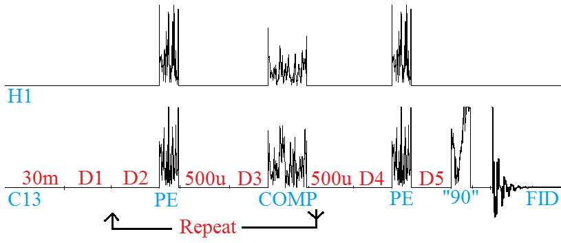
Ideally, the polarization of C1 saturated at . Process 2, aimed to maximize is composed of Process 1 followed by a wait step for duration D4, and by PE(H C2) to cool C2, ideally reaching (see Figure 3). The goal of Process 3 is to maximize , hence we apply Process 2, followed by a wait step for duration D5, ideally reaching (see Figure 4). In all cases, a read-out pulse was applied on the spin of interest prior to acquisition.
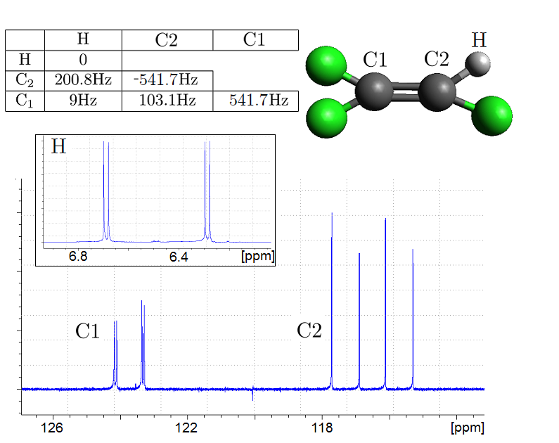
In the experiment, the measured relaxation times (see table 1), were obtained by inversion recovery as in Brassard et al. (2005); Atia et al. (2014). Adding a paramagnetic reagent to the TCE, improved the relaxation time ratios as suggested in Fernandez et al. (2005). We simulated the three processes using the experimental delays and measured relaxation times, while assuming perfect pulses. According to the simulation, the polarization of C1 could be enhanced by a factor of 5.49 after seven rounds (, see also Figure 6) via Process 1, the polarization of the two carbon spins could reach 4.78 and 3.70 () via Process 2. The polarization of three spins could reach () via Process 3.
The implemented PE and compression pulses were generated using SIMPSON version 3.0 Bak et al. (2000); Tos̆ner et al. (2008), an open source program implementing GRAPE. The pulses were designed to be robust to deviations up to 15% in RF power Atia et al. (2014). The pulses were not designed to apply a specific unitary gate, but to apply a less constraining state-to-state transformation. However the state of the system changes with each cooling cycle. Therefore, among two pulses that apply PE, even though one pulse performs better in equilibrium Atia et al. (2014), we used another pulse, which yielded better cooling for the entire process. Let stand for the diagonal of a density matrix in the computation basis. The PE pulse was designed to evolve the system from equilibrium
| (5) |
to a finite state,
| (6) |
where . The two states are represented here 111In the actual design we used the more precise ratio of 3.98, but in the explanation here we use 4 for clarity. in product operator formalism as the reduced (shifted and scaled Elias et al. (2006)) diagonal density operator Cory et al. (1996); Atia et al. (2014). The compression pulse (COMP) was designed to evolve the system from
| (7) |
(a state of three spins with identical polarizations) to
| (8) |
We chose this final state, as the four highest probabilities correspond to the four states where C1’s spin is 0, namely, . Notice that the polarization-increase factor of C1 is 1.5, the maximum possible under unitary transformations, as mentioned above.
III Results
After seven rounds (see Figure 6), the system reached its limit cycle and no more improvement could be expected. In Process 1, C1 was cooled by a factor of , with , significantly higher than 17.84, the of the entire spin system at equilibrium (see Figures 6 and 5). Alternatively, we see that the polarization bypassed the information theoretical bound of . In Process 2 we maximized , by adding another delay, D4 (that happened to be equal to D2=5s in the optimal case), followed by PE. We obtained polarizations of and (of C1 and C2 respectively), with . In Process 3 we maximized the total , using an additional delay D5=6s before the measurement (in addition, D4 was modified to 6s). The measured polarizations were , and (for C1, C2, and H respectively), with of .
There is a gap between SIMPSON’s very high predicted pulse efficiency and the lab results (see Atia et al. (2014)). The polarization of C2 following a PE pulse was (0.95 efficiency), and a COMP pulse applied on equilibrium state resulted with (0.92 efficiency). The main error factors are the hardware’s imperfection distorting the pulses Barbara et al. (1991), and the pulses themselves being prepared without taking into account the -relaxation (see table 1) during the system evolution. The first factor could be negated using a technique mentioned in Ryan et al. (2008). Once the measured gate-efficiencies of 0.95 and 0.92 are added into the simulation, the simulated per round fit near-perfectly the measured , see Figures 6 and 7.
| H | C2 | C1 | |
|---|---|---|---|
| T1 | |||
| T |
C1 Information Content Buildup
| Round | Polarization | Carbon’s |
|---|---|---|
| 0 | 1.00 | 1.00 0.04 |
| 1 | 3.40 | 11.56 0.14 |
| 2 | 3.98 | 15.84 0.16 |
| 3 | 4.34 | 18.84 0.17 |
| 4 | 4.49 | 20.16 0.18 |
| 5 | 4.55 | 20.70 0.18 |
| 6 | 4.59 | 21.07 0.18 |
| 7 | 4.61 | 21.25 0.18 |
| 10 | 4.59 | 21.07 0.18 |
IV Summary
Using optimal control, we demonstrated the first single-round and multiple round AC applied on liquid state NMR. We bypassed Shannon’s bound in three different processes. The current optimal control methods (GRAPE), and better ones such as a second order GRAPE de Fouquieres et al. (2011) and Krotov based optimization Maximov et al. (2008) could enable various applications of AC in magnetic resonance spectroscopy Mor et al. (2005); Elias et al. (2011a); Brassard et al. (2014) and maybe also other potential applications Rempp et al. (2007); Henrich et al. (2007); Weimer et al. (2008); Briegel and Popescu (2008); Linden et al. (2010); Criger et al. (2011); Renner (2012); Blank (2013); Xu et al. (2014); Lloyd (2014).
V Acknowledgments
We thank Prof. Asher Schmidt and Dr. Yael Balasz for enlightening discussions. This work was supported in part by the Wolfson Foundation and the Israeli MOD Research and Technology Unit. YE thanks the Institut Transdisciplinaire d’Information Quantique.
References
- Simon (1994) D. Simon, in Foundations of Computer Science, 1994 Proceedings., 35th Annual Symposium on the Foundations of Computer Science (1994), pp. 116–123.
- Shor (1997) P. W. Shor, SIAM J. Comp. 26, 1484 (1997).
- Harrow et al. (2009) A. W. Harrow, A. Hassidim, and S. Lloyd, Phys. Rev. Lett. 103, 150502 (2009).
- Briegel et al. (1998) H.-J. Briegel, W. Dür, J. I. Cirac, and P. Zoller, Phys. Rev. Lett. 81, 5932 (1998).
- Boykin et al. (2002) P. O. Boykin, T. Mor, V. Roychowdhury, F. Vatan, and R. Vrijen, Proc. Natl. Acad. Sci. USA 99, 3388 (2002).
- Fernandez et al. (2004) J. M. Fernandez, S. Lloyd, T. Mor, and V. Roychowdhury, Int. J. Quant. Inf. 2, 461 (2004).
- Schulman et al. (2005) L. J. Schulman, T. Mor, and Y. Weinstein, Phys. Rev. Lett. 94, 120501 (2005).
- Raeisi and Mosca (2015) S. Raeisi and M. Mosca, Phys. Rev. Lett. 114, 100404 (2015).
- Rodriguez-Briones and Laflamme (2015) N. A. Rodriguez-Briones and R. Laflamme, arXiv:1412.6637 (2015).
- Park et al. (2015) D. K. Park, N. A. Rodriguez-Briones, G. Feng, R. Rahimi-Darabad, J. Baugh, and R. Laflamme, arXiv:1501.00952 (2015).
- Knill et al. (1998) E. Knill, R. Laflamme, and W. H. Zurek, Proc. Roy. Soc. London, Ser. A 454, 365 (1998).
- Aharonov and Ben-Or (1997) D. Aharonov and M. Ben-Or, in Proc. STOC (ACM, 1997), pp. 176–188.
- Mor et al. (2005) T. Mor, V. Roychowdhury, S. Lloyd, J. M. Fernandez, and Y. Weinstein, US patent No. 6,873,154 (2005).
- Elias et al. (2011a) Y. Elias, H. Gilboa, T. Mor, and Y. Weinstein, Chem. Phys. Lett. 517, 126 (2011a).
- Cory et al. (1996) D. G. Cory, A. F. Fahmy, and T. F. Havel, in Proceedings of the Fourth Workshop on Physics and Computation (1996), pp. 87–91.
- Cory et al. (2000) D. G. Cory, R. Laflamme, E. Knill, L. Viola, T. F. Havel, N. Boulant, G. Boutis, E. Fortunato, S. Lloyd, R. Martinez, et al., Fortschr. Phys. 48, 875 (2000).
- Glaser (2001) S. J. Glaser, Angewandte Chemie 40, 147 (2001).
- Vandersypen and Chuang (2005) L. M. K. Vandersypen and I. L. Chuang, Rev. Mod. Phys. 76, 1037 (2005).
- Jones (2011) J. A. Jones, Prog. NMR Spectrosc. 59, 91 (2011).
- Gershenfeld and Chuang (1997) N. A. Gershenfeld and I. L. Chuang, Science 275, 350 (1997), URL http://citeseer.nj.nec.com/gershenfeld97bulk.html.
- Boykin et al. (2010) P. O. Boykin, T. Mor, V. Roychowdhury, and F. Vatan, Nat. Comp. 9, 329 (2010).
- Cover and Thomas (2006) T. Cover and J. Thomas, Elements of Information Theory, Wiley Series in Telecommunications and Signal Processing (Wiley-Interscience, 2006), ISBN 9780471241959.
- Brassard et al. (2005) G. Brassard, Y. Elias, J. M. Fernandez, H. Gilboa, J. A. Jones, T. Mor, Y. Weinstein, and L. Xiao, arxiv:quant-ph/0511156 (2005), eprint arXiv:quant-ph/0511156.
- Elias et al. (2007) Y. Elias, J. M. Fernandez, T. Mor, and Y. Weinstein, in Proceedings of Unconventional Computation (Springer publishing, 2007), vol. 4618, pp. 2–26.
- Sørensen (1989) O. W. Sørensen, Prog. Nucl. Mag. Res. Spec. 21, 503 (1989).
- Schulman and Vazirani (1999) L. J. Schulman and U. V. Vazirani, in ACM Symposium on the Theory of Computing (STOC): Proceedings (1999), pp. 322–329.
- Fernandez (2003) J. M. Fernandez, Ph.D. thesis, University of Montreal, Canada (2003).
- Elias et al. (2006) Y. Elias, J. M. Fernandez, T. Mor, and Y. Weinstein, Isr. J. Chem. 46, 371 (2006).
- Schulman et al. (2007) L. J. Schulman, T. Mor, and Y. Weinstein, SIAM J. Comp. 36, 1729 (2007).
- Elias et al. (2011b) Y. Elias, T. Mor, and Y. Weinstein, Phys. Rev. A 83, 042340 (2011b).
- Morris and Freeman (1979) G. A. Morris and R. Freeman, J. Am. Chem. Soc. 101, 760 (1979).
- Chang et al. (2001) D. E. Chang, L. M. Vandersypen, and M. Steffen, Chem. Phys. Lett. 338, 337 (2001).
- Baugh et al. (2005) J. Baugh, O. Moussa, C. A. Ryan, A. Nayak, and R. Laflamme, Nature 438, 470 (2005).
- Ryan et al. (2008) C. A. Ryan, O. Moussa, J. Baugh, and R. Laflamme, Phys. Rev. Lett. 100, 140501 (2008).
- Khaneja et al. (2005) N. Khaneja, T. Reiss, C. Kehlet, T. Schulte-Herbrüggen, and S. J. Glaser, J. Mag. Reson. 172, 296 (2005).
- Atia et al. (2014) Y. Atia, Y. Elias, T. Mor, and Y. Weinstein, Int. J. Quant. Inf. 12, 1450031 (2014).
- Fernandez et al. (2005) J. M. Fernandez, T. Mor, and Y. Weinstein, Int. J. Quant. Inf. 3, 283 (2005).
- Bak et al. (2000) M. Bak, J. T. Rasmussen, and N. C. Nielsen, J. Mag. Reson. 147, 296 (2000), ISSN 1090-7807.
- Tos̆ner et al. (2008) Z. Tos̆ner, T. Vosegaard, C. Kehlet, N. Khaneja, S. Glaser, and N. Nielsen, J. Mag. Reson. (2008).
- Note (1) Note1, in the actual design we used the more precise ratio of 3.98, but in the explanation here we use 4 for clarity.
- Barbara et al. (1991) T. M. Barbara, J. F. Martin, and J. G. Wurl, Journal of Magnetic Resonance (1969) 93, 497 (1991).
- de Fouquieres et al. (2011) P. de Fouquieres, S. Schirmer, S. Glaser, and I. Kuprov, J. Mag. Reson. 212, 412 (2011).
- Maximov et al. (2008) I. I. Maximov, Z. Tošner, and N. C. Nielsen, J. Chem. Phys. 128, 184505 (2008).
- Brassard et al. (2014) G. Brassard, Y. Elias, T. Mor, and Y. Weinstein, Eur. Phys. J. Plus 129, 258 (2014).
- Rempp et al. (2007) F. Rempp, M. Michel, and G. Mahler, Phys. Rev. A 76, 032325 (2007).
- Henrich et al. (2007) M. J. Henrich, F. Rempp, and G. Mahler, Eur. Phys. J. Spec. Top. 151, 157 (2007).
- Weimer et al. (2008) H. Weimer, M. J. Henrich, F. Rempp, H. Schröder, and G. Mahler, Europhys. Lett. 83, 30008 (2008).
- Briegel and Popescu (2008) H. J. Briegel and S. Popescu, arxiv:0806.4552 (2008), eprint arXiv:0806.4552.
- Linden et al. (2010) N. Linden, S. Popescu, and P. Skrzypczyk, Phys. Rev. Lett. 105, 130401 (2010).
- Criger et al. (2011) B. Criger, O. Moussa, and R. Laflamme, arxiv:1103.4396 (2011), eprint arxiv:1103.4396.
- Renner (2012) R. Renner, Nature 482, 164 (2012).
- Blank (2013) A. Blank, Quantum Inf. Processing 12, 2993 (2013).
- Xu et al. (2014) J.-S. Xu, M.-H. Yung, X.-Y. Xu, S. Boixo, Z.-W. Zhou, C.-F. Li, A. Aspuru-Guzik, and G.-C. Guo, Nat. Photonics 8, 113 (2014).
- Lloyd (2014) S. Lloyd, Nat. Photonics 8, 90 (2014).
Carbons’ Information Content Buildup