The Effects of Initial Abundances on Nitrogen in Protoplanetary Disks
Abstract
The dominant form of nitrogen provided to most solar system bodies is currently unknown, though available measurements show that the detected nitrogen in solar system rocks and ices is depleted with respect to solar abundances and the interstellar medium. We use a detailed chemical/physical model of the chemical evolution of a protoplanetary disk to explore the evolution and abundance of nitrogen-bearing molecules. Based on this model we analyze how initial chemical abundances, provided as either gas or ice during the early stages of disk formation, influence which species become the dominant nitrogen bearers at later stages. We find that a disk with the majority of its initial nitrogen in either atomic or molecular nitrogen is later dominated by atomic and molecular nitrogen as well as NH3 and HCN ices, where the dominant species varies with disk radius. When nitrogen is initially in gaseous ammonia, it later becomes trapped in ammonia ice except in the outer disk where atomic nitrogen dominates. For a disk with the initial nitrogen in the form of ammonia ice the nitrogen remains trapped in the ice as NH3 at later stages. The model in which most of the initial nitrogen is placed in atomic N best matches the ammonia abundances observed in comets. Furthermore the initial state of nitrogen influences the abundance of N2H+, which has been detected in protoplanetary disks. Strong N2H+ emission is found to be indicative of an N2 abundance greater than , in addition to tracing the CO snow line. Our models also indicate that NO is potentially detectable, with lower N gas abundances leading to higher NO abundances.
I. Introduction
Most solar system bodies are depleted in nitrogen relative to the Sun and the ISM. Pontoppidan et al. (2014) compare the CNO abundances in various solar system bodies relative to silicon. Comets Halley and Hale-Bopp, which likely formed in the outer disk ( AU), where there is thought to be less chemical reprocessing, are depleted in nitrogen by less than an order of magnitude with respect to solar values. In contrast the nitrogen content of meteorites is between one and three orders of magnitude below the amount of nitrogen that was available, as traced by the Sun (Asplund et al., 2009). In fact, comets and meteorites exhibit greater depletion in nitrogen than in other volatiles such as oxygen and carbon (Pontoppidan et al., 2014). In this context the Earth is extremely depleted in nitrogen with an abundance ratio more than five orders of magnitude below the solar abundance. Most of the known nitrogen resides in the atmosphere in the form of N2, however, it is possible that much of Earth’s nitrogen was locked in its interior (Roskosz et al., 2013). The ratio of the terrestrial surface, which includes the atmosphere and oceans, as well as the crust, agrees with that of chondrites, suggesting that both the Earth’s surface and meteorites obtained their nitrogen from the same reservoir (Marty, 2012). It remains unclear what the dominant nitrogen-bearing species was upon delivery to the young Earth, whether it was carried by organics in meteorites, N2 from the solar nebular gas, or NH3/organics in cometary bodies (Epstein et al., 1987; Wyckoff et al., 1991; Owen et al., 2001; Kawakita et al., 2007).
The Cronian satellites Titan and Enceladus both show evidence of rich N2 atmospheres (Niemann et al., 2005; Waite et al., 2006). Isotopic abundances in Titan’s atmosphere were measured by the Huygens probe and the low 36Ar/14N ratio along with the absence of detectable of 38Ar, Kr and Xe provides circumstantial evidence that Titan first received its nitrogen in a less volatile form, such as NH3 (Niemann et al., 2005). The nitrogen could later be converted to the more volatile N2, possibly by impacts during the period of late heavy bombardment (Sekine et al., 2011).
Which nitrogen-bearing molecules end up in solar system bodies depends on the chemical composition of the protoplanetary disk at the time of planetesimal formation. In this paper we show that the dominant bearer of nitrogen is highly dependent on initial chemical abundances. There continues to be some uncertainty in regards to the nitrogen partitioning in dense molecular pre-stellar cores, which represent the initial conditions. This uncertainty stems from the difficulty of detecting many of the most probable nitrogen reservoirs: N, N2, and nitrogen-bearing ices. N and N2 are not directly observable in the dense ISM. Instead their abundances must be inferred from observations of trace molecules such as N2H+, which is a reaction product of N2. NH3 ice abundances are derived from absorption features. However, the measured NH3 ice abundances are uncertain due to the blending of particular absorption features with those of water and silicates (Öberg et al., 2011a).
Spectroscopic observations of ices toward low-mass young stellar objects as part of the Spitzer “Cores to Disks” program find that on average 10% of the total nitrogen is contained in known ices, primarily NH3, NH, and XCN (OCN-), though in some sources the percentage is as high as 34% (Öberg et al., 2011a). The remaining nitrogen is posited to reside in the gas phase as either atomic N or N2. Womack et al. (1992) estimate N2 abundances in multiple dense molecular cores using observations of N2H+. They find an average fractional abundance of 4 with respect to H2, or of the total nitrogen reservoir assuming solar abundances (Asplund et al., 2009). Maret et al. (2006) find the gas phase nitrogen to be primarily in atomic as opposed to molecular nitrogen for the prestellar core B68, though based on their models the main nitrogen-bearing species is NH3 ice. Similarly, Daranlot et al. (2012) conclude that 45% of the total elemental nitrogen in dense clouds is in the form of NH3 ices on grains, though the abundances they predict are larger than those observed. Le Gal et al. (2014) modeled the gas phase nitrogen chemistry in dark clouds. Starting with nitrogen all in gas phase N they find that once a steady state is reached the dense core contains equal abundances of N and N2 with a small fraction of the initial nitrogen in other species.
NH3 has long been a tracer of dense cores (e.g. Benson & Myers, 1989). Using detections of NH3 inverse transitions toward five starless cores, Tafalla et al. (2002) calculated NH3 gas abundances ranging to with respect to H2. NH3 gas has also been observed in absorption several thousand AU from the Class 0 protostar IRAS 16293-2422 with an abundance relative to H2 of (Hily-Blant et al., 2010). Finally, Le Gal et al. (2014) find that the steady state abundances of nitrogen hydrides in their chemical model were in good agreement with those observed toward IRAS 16293-2422. In sum, in prestellar cores, gas phase NH3 is clearly not a major nitrogen reservoir, however as discussed earlier there is a significant amount of NH3 potentially present in the ices. Visser et al. (2011) modeled the chemical evolution of a collapsing protostar from a pre-stellar core to a disk, finding that the disk begins with most of the nitrogen in gas phase N2 with minor contributions from N, NH3, and NO.
Despite detections in these earlier stages of star formation there are currently no published detections of NH3 gas in protoplanetary disks, though upper limits exist for several T Tauri stars in the near-infrared (Salyk et al., 2011; Mandell et al., 2012). However, both CN and HCN have been detected in multiple protoplanetary disks (e.g. Öberg et al., 2011b; Guilloteau et al., 2013) and resolved N2H+ emission is seen in the T Tauri system TW Hya (Qi et al., 2013) while unresolved emission is seen toward several more systems (Dutrey et al., 2007; Öberg et al., 2010, 2011b).
Thus a variety of potential initial distributions of the total nitrogen reservoir could be provided to the forming disk. It is possible that a substantial fraction of the nitrogen could be in the form of N gas, N2 gas, or NH3 ices. Alternatively, if the source is warm enough during collapse, a significant amount of NH3 could be provided to the disk as NH3 gas. In this paper we perform simulations of the disk chemistry in which we make four different initial abundance assumptions: (1) most of the nitrogen is in atomic form; (2) most of the nitrogen arrives in the disk in molecular form; (3) the nitrogen arrives as NH3 ice; (4) most of the nitrogen arrives as NH3 gas.
II. Model
We use the disk chemistry model of Fogel et al. (2011) to explore the effects of different initial abundances. We first set the physical structure of the disk, including temperature, density, and dust properties. Next we perform UV and X-ray radiative transfer, assuming all radiation is from the central star. The model then calculates chemical abundances based on a network of 5903 chemical reactions and specified initial abundances. The specifics of the model are discussed in greater detail below.
II.1. Physical Structure
We use the two-dimensional, azimuthally symmetric disk physical structure adopted by Cleeves et al. (2013). This model is designed to represent a ‘typical’ T-Tauri disk based on the transition disk observations presented by Andrews et al. (2011). The density structure is fixed and of the form:
| (1) |
Here and are the characteristic surface density and radius, taken to be 3.1 g cm-2 and 135 AU respectively. The disk is a settled disk, =0.1 , where is the dust-to-gas mass ratio of dust grains in the upper disk relative to the standard value of 0.01 (D’Alessio et al., 2006). Smaller values indicate less dust in the upper disk and more dust in the midplane. Two types of dust are included: small, micron size grains and larger millimeter size grains. The grain distribution is given by:
| (2) |
| (3) |
and
| (4) |
The height profile given by Equation (4) is applied to both the small dust grains and the gas, with a characteristic scale height of = 12 AU and = 0.3. The scale height for the large grains is smaller by a factor of . 85% of the total dust mass is in the large grains such that = 0.85. The dust density and temperature distributions are shown in Figure 1.
II.2. Radiation Field
The FUV field from the central star, including Ly radiation, and the stellar X-ray field were generated using a Monte Carlo radiative transfer and scattering model as described by Bethell & Bergin (2011b, a). We adopt the FUV spectrum to be that measured for TW Hya (Herczeg et al., 2002, 2004). We assume a thermal X-ray spectrum between 1 and 10 keV with an integrated X-ray luminosity of erg s-1, which is typical for a T Tauri star (Glassgold et al., 1997). We then compute the X-ray attenuation using the cross-sections of Bethell & Bergin (2011a).
Ly radiation contains of the total FUV flux (Herczeg et al., 2004; Bergin et al., 2003). Additionally several species have photodissocation cross sections close to Ly. For these reasons, Ly radiation cannot be ignored, as is the case for the weaker UV emission lines (Fogel et al., 2011). In addition to scattering off dust grains, Ly photons will first isotropically scatter off of hydrogen atoms on the top of the disk surface. This layer scatters a fraction of the Ly radiation more directly towards the midplane, allowing the Ly radiation greater penetrating power than the whole of the FUV continuum and lines beyond Ly (Bethell & Bergin, 2011b).
II.3. Reaction Network
We use the chemical model of Fogel et al. (2011), which is based on the gas-phase reaction network of the Ohio State University Astrophysical Chemistry Group (Smith et al., 2004) and modified to include the updated reaction rates of McElroy et al. (2013). This network does not include the expansions for reactions at high temperatures from Harada et al. (2010). Thus the predictions for the inner edge of the disk may change. However, in this paper we focus on the abundances of molecules with high volatility at radii beyond a few AU.
The chemical code is run at 74 radii with each radius broken into 45 vertical zones. The grid spacing is logarithmic in radius and linear in angle. The chemistry in each vertical zone is run independently, except for the considerations needed for self-shielding, which is treated vertically, with no mixing between zones. A pseudo two-dimensional result is obtained by running the model for many radii. The model includes photodesorption, photodissociation, freeze out, grain surface reactions, gas phase ion and electron reactions, and cosmic ray and stellar X-ray ionization as well as self-shielding of H2 and CO. Cosmic rays are assumed to strike the disk vertically with an unshielded ionization rate of s-1. The photodissociation rates depend on the strength of the radiation field at a given point in the disk and the molecule’s cross section. Grain surface reactions are limited to the formation of H2, H2O, NH3, and CH4 via successive hydrogenation. The self-shielding and grain surface reactions are time dependent and the chemistry is run for 3 Myr.
II.4. Initial Conditions
We present the results from four chemical models, each with different initial conditions as listed in Table 1. Model N uses the initial abundances of Fogel et al. (2011), with most nitrogen originating in atomic form. None of the initial nitrogen is in ices. Most of the oxygen is provided as either CO, , or water ice, , with a small fraction of the oxygen in other gas phase species. These values are for the model molecular cloud of Aikawa & Herbst (1999), which is in good agreement with observed molecular abundances in cores (e.g. Terzieva & Herbst, 1998).
In Model NH3(gr) most of the nitrogen is in NH3 ice and there is initially no atomic nitrogen. This is a simplification of the Maret et al. (2006) and Daranlot et al. (2012) models which predict large NH3 ice abundances. Model NH3 differs from Model NH3(gr) in that it starts with NH3 in the gas phase. This model is only viable if the collapse of the initial molecular cloud liberates NH3 from grains. Finally, Model N2 starts with the nitrogen primarily in N2. As discussed above, gas phase N and N2 are not directly observable, making it difficult to observationally determine the relative gas phase abundances. Model N2, when compared to Model N, allows us to determine whether the partitioning between N and N2 has an observable effect on the chemistry at later stages. We emphasize that the variations in the initial conditions of our models do not represent the most likely nitrogen distribution in the disk. Rather, they are extreme examples meant to illustrate the effect the initial nitrogen distribution has on the chemistry at later stages.
III. Model Results
III.1. Model N
III.1.1 Radial and Vertical Structure
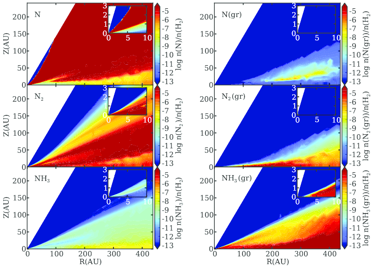
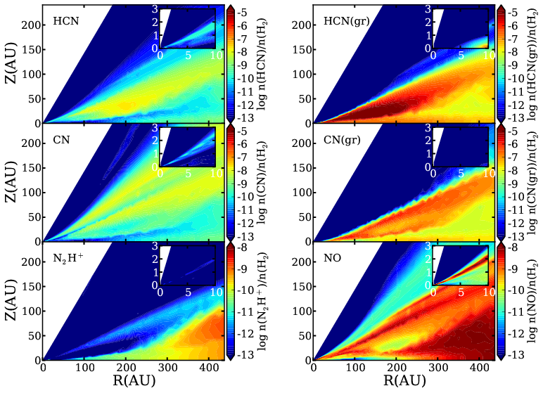
The following results are for a chemical time of 1 Myr unless otherwise stated. The abundances of the major nitrogen species are shown for a cross section of the disk in Figures 2 and 3. In the cold midplane () the thermal desorption rates are low, allowing many species to freeze out onto ices. Above the midplane the ices have evaporated and the chemistry is able to process N into N2 as well as NH3 ice. This region corresponds to the ‘warm molecular layer’ (Aikawa et al., 2002; Bergin et al., 2007; Henning & Semenov, 2013; Dutrey et al., 2014). At = 200 AU the warm molecular layer extends vertically from 60 AU. In the upper, photon dominated region of the disk molecules are destroyed quickly and atomic nitrogen dominates.
Figure 4 shows the vertical structure of nitrogen carriers at a radius of 200 AU. This far from the central star, N2 ice is only abundant close to the midplane where the gas temperature is low, 20 K, and molecules are shielded from radiation from the central star. However, the midplane is dominated by NH3 ice. The majority of the NH3 ice in the midplane is formed on the grains, rather than resulting from freeze out of NH3 gas. Closer to the star N2 ice evaporates and HCN ice, which has a higher binding energy, is present in greater abundance (see Figure 5).
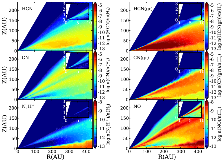
Inside = 200 AU chemical processing converts the N gas into N2 in the midplane. At the disk surface N is also able to form NH3, CN, and HCN gas. For 10 AU these molecules are able to remain in the gas phase in the surface layers, while for 10 AU they adsorb onto dust grains.
The highest concentration of NH3 and NH3 ice in the disk is in the range 20 AU except in the outer disk, where NH3 ice remains highly abundant at 50 AU (Figure 2). In addition to forming on grains, NH3 is the end result of a series of ion-neutral reactions and forms quickly in these regions. Due to its high binding energy, NH3 ice acts as a sink, leaving little NH3 in the gas phase. However, near the midplane there is a residual abundance of N2 and NH3. Cosmic ray desorption prevents N2 from completely adsorbing onto grains. Instead, N2 remains active in the gas phase chemistry, allowing the continued formation of NH3. This chemistry is sensitive to the binding energies of molecules such as N2 on grains and to the presence/absence of ionizing photons. However, these binding energies are often uncertain and the presence of cosmic rays in the midplane has been called into question (Cleeves et al., 2013). This uncertainty will be discussed in more detail in Section 3.3.
CN and HCN gas phase abundances are low in the cold midplane region (Figure 3). These molecules are formed via gas phase reactions and only exist in abundance in the warm molecular layer. After forming, CN and HCN quickly adsorb onto dust grains. Thus CN and HCN ices also exist in the molecular layer. At = 200 AU, HCN ice becomes the dominant form of nitrogen at heights between 10 and 30 AU (Figure 4). Because much of the CN goes into forming HCN and N2 before it can freeze out, a similar peak is not observed in CN ice.
For 100 AU, N2H+ traces the midplane (Figure 3). Inside 100 AU, N2H+ is destroyed via gas phase reactions with CO, which does not exist in abundance in the midplane for 100 AU. NO, a precursor molecule to N2, is most abundant in the surface layers ( AU at AU), where the main formation and destruction mechanisms are:
| (5) |
and
| (6) |
In the surface layers OH is slightly more abundant than NO, allowing the creation of NO to outpace its destruction.
III.1.2 Radial Variation in the Midplane
Figure 5 illustrates the snow lines for nitrogen-bearing species in the midplane. At a radius of 100 AU in the midplane, N2 and N have evaporation temperatures of 14.8 K and 15 K respectively. These temperatures were calculated using Eqn. 5 from Hollenbach et al. (2009) and the binding energies in Table 1. In comparison, the evaporation temperatures of HCN and NH3 are 38 K and 57 K. While it is fairly easy to free N and N2 from grains in the midplane, HCN and NH3 remain locked in ices outside of 17 AU and 5 AU respectively. This range of evaporation temperatures results in a series of sublimation fronts. The dearth of ices at small radii does not correspond with an increase in the gas phase abundance of the same species. Instead, inside 150 AU the majority of the nitrogen makes its way into N2 via chemical processing. This process is discussed in more detail in Section 3.1.3.
Early in the chemical evolution of the disk, most of the HCN gas in the midplane either freezes out onto grains or is destroyed via gas phase reactions with ions. Because of its high binding energy, it remains on grains for radii greater than 17 AU. The same process occurs for the NH3 and CN gas, resulting in a substantial fraction of the total nitrogen locked in HCN and NH3 ices in the midplane beyond 17 AU.
The resulting reservoir of moderately volatile ices could be used to form more complex molecules, thus changing the picture presented above. NH3 and HCN are both needed to form aminomethanol, a precursor to glycine, in ices via Strecker synthesis (Danger et al., 2012). The same ices are also capable of forming hydroxyacetonitrile. In addition hydrogenation of HCN can result in the formation of methylamine on grain surfaces (Theule et al., 2011).
Ices in the presence of UV radiation have been shown to form more complex molecules (e.g. Bernstein et al., 2002). For example, irradiation of NH3 ice at 10 K can lead to the formation of NH2 and N2H4 while N2 becomes N3 (Gerakines et al., 1996). Especially in the warm molecular layer, which is more transparent to UV photons that the midplane, the abundance of NH3, N2, and HCN ices could decreases, corresponding to an increase in more complex species.
Turbulent mixing would likely transport ices from the midplane to the warmer upper regions of the disk, where desorption would remove the molecules from grains (Furuya & Aikawa, 2014). Once in the gas phase molecules such as NH3 would be dissociated, with the nitrogen eventually going into either N2 or N depending on the local disk temperature. Additionaly, planetesimal drift and advection would bring ice coated grains to smaller radii (Weidenschilling & Cuzzi, 1993; Ciesla & Cuzzi, 2007). There they would evaporate, likely contributing to the gas phase N2 abundance.
III.1.3 Time Evolution
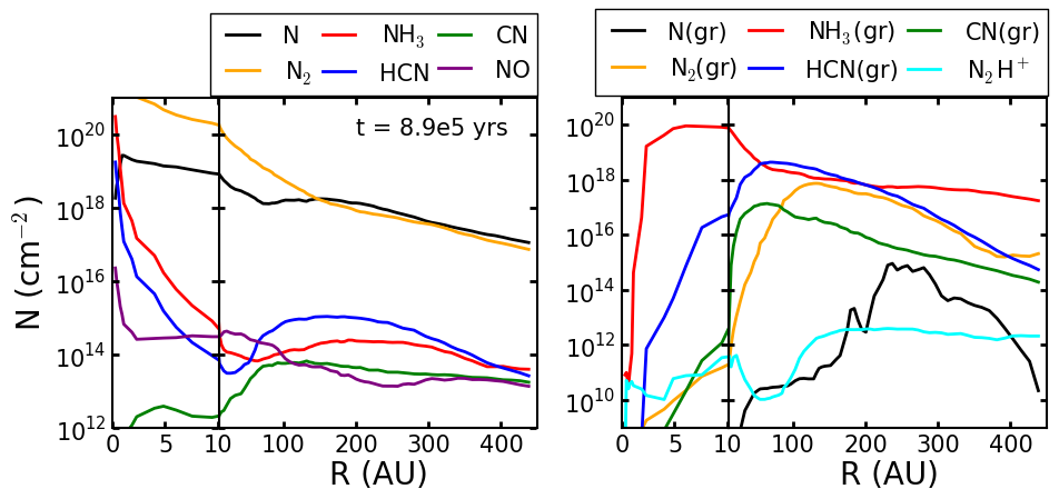
To explore time dependent behavior throughout the disk the abundances are collapsed to radial column density plots by integrating over the vertical direction (Figure 6). These plots provides the most complete information at a given stage in addition to allowing easy examination of the time evolution of the chemistry.
At early stages, atomic N, where the majority of the nitrogen initially resides, and N2 dominate. There is a general evolution of N becoming N2 on fairly short time scales via gas phase reactions with CN and NO. These are both two step reactions:
| (7) |
| (8) |
and
| (9) |
| (10) |
though other reactions can also create CN and NO. The C and O are released when CO reacts with He+ (Bergin et al., 2014). Beyond 50 AU these reactions primarily take place in the warm molecular layer. Inside 50 AU the same reactions place a majority of the initial N into N2 early on. At = 8.9 years in our model the N gas column density still surpasses that of N2 beyond = 200 AU. Inside of 200 AU the presence of gas phase CO allows for more O to be present in the midplane. Some of this O goes into OH, leading to the formation of N2 as discussed previously. The evaporation timescale increases with temperature, so as time passes larger radii begin to be affected by evaporation. For N the evaporation timescale in the midplane at 180 AU is years. This, in conjunction with the formation of NH3 on grains, destroys the N snow line at late stages.
Once it freezes out onto grains, N ice is quickly converted to NH3 ice. Over time this depletes the N ice reservoir. More of the nitrogen becomes locked in NH3 and HCN ices, with HCN ices becoming the dominant nitrogen-bearing species between 60 AU and 170 AU for late stages. Closer to the central star HCN is more likely to be photo-dissociated before it can freeze out onto the grains.
As more of the total nitrogen becomes trapped in ices the abundances of the molecules needed to form NH3, such as NH, drop and the formation rate of gas phase NH3 slows. This is also true for the precursors of HCN. Thus there is little change in NH3 ice and HCN ice abundances at late stages.
III.2. Changes in Initial Conditions
In Model NH3(gr) the initial gas phase atomic N has been replaced with NH3 ice. Radiation from the central star is unable to liberate the NH3 except at radii less than 5 AU and NH3 ice remains the dominant bearer of nitrogen for all times considered in our model (Figure 7). Abundances of the remaining molecules are much lower than those in Model N since most of the nitrogen remains in NH3 ice and does not participate in the chemistry (Figures 8 and 9).
Model NH3 places the majority of the initial nitrogen in NH3 gas. At late stages the nitrogen partitioning is very similar to that in Model NH3(gr), though there are several key differences (Figures 10-12). NH3 becomes trapped on grains in the warm molecular layer and the midplane early on. Before freezing out some of the gas phase NH3 is able to react with other molecules. Because of this there is more N2 gas, as well as HCN ice and CN ice, in Model NH3 than in Model NH3(gr). The formation of additional N2 depletes the NO, such that Model NH3 has slightly lower NO abundances than those seen in Model NH3(gr). In the midplane the larger N2 abundance also leads to the creation of more N2H+ beyond 300 AU when compared to Model NH3(gr). In the surface layers NH3 gas does not freeze out as quickly as it does closer to the midplane. Gas phase reactions are able to remove a larger fraction of the nitrogen from NH3, most of which becomes N and N2 gas.
Model N2, where most of the nitrogen is initially in gas phase N2, results in a nitrogen partitioning very similar to that of Model N (Figures 13 - 15). That the differences are so subtle indicates that the disk is able to efficiently transfer N to N2, assuming there is no substantial processing of N on grains limiting the availability of atomic N in the gas. Together, Model N and Model N2 illustrate that if the nitrogen is delivered to the disk primarily as either atomic or molecular nitrogen, the disk will likely be able to produce significant amounts of N2 gas via the reactions discussed previously.
III.3. The Effects of Binding Energies
Much of the chemistry explored in this work depends on the amount of nitrogen available for gas phase reactions. In other words, it depends on the desorption rates, which are extremely sensitive to the binding energies used. The residual midplane abundance of NH3 in Figure 2 is present because the evaporation temperature of N2 is low enough to allow gas phase N2 to exist in the midplane. In the absence of chemical processing the gas to ice ratio is set by balancing freeze out with thermal and cosmic ray desorption:
| (11) |
where is the number density of species X, is the vibrational frequency of N2 bound to the grain, K is the binding energy of N2 (Öberg et al., 2005), K is the dust temperature at AU in the midplane, s-1 is the cosmic ray desorption rate, is the collisional cross section of a 0.1 micron dust grain, is the sound speed, and is the sticking coefficient, assumed to be 1. At a radius of 100 AU in the midplane this gives . The actual ratio for Model N is , indicating that chemical processing and gas phase formation have a non-negligible effect on the ratio.
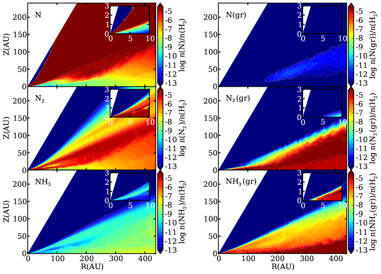
Unfortunately it is not clear what assumptions should be made when determining binding energies experimentally. The binding energy depends both on the species being bound to the grain and the composition of the grain’s surface. Commonly used surfaces include CO, H2O, silicates (Bergin et al., 1995), and more recently CO2 (Cleeves et al., 2014). The binding energies of molecules on ices can be calculated or measured in the lab. In Model N the binding energy of N2 is 790 K (corresponding to an evaporation temperature of K in the midplane at 100 AU) and the binding energy of CO is 855 K ( K), as determined by Öberg et al. (2005). These binding energies assume an N2 and CO coated grain surface respectively and are appropriate for dust temperatures near 17 K. Figures 16 and 17 show the resulting chemical abundances when the binding energies for CO and N2 are both changed to 1110 K ( K), as is appropriate for CO2 coated grains and dust temperatures between 25 K and 50 K (Cleeves et al., 2014).
Changing just these two binding energies has a noticeable effect on the chemical abundances (Figures 16 and 17). The residual N2 gas near the midplane is gone, in addition to the lower abundances of N and N2 gas in the warm molecular layer. The abundances of most nitrogen-bearing ices has decreased. However, much of the nitrogen in N2 gas in Figure 2 is now trapped in N2 ice, particularly in the outer disk. With less gas phase N2 available, the amount of NH3 gas inside of 200 AU has also dropped.
The total amount of N2H+ in the outer disk does not change, though it is less concentrated in the midplane and more abundant in the warm molecular layer compared to Model N. The outer disk contains more NO in the high binding energy model. With less N in the gas phase to react with, NO is not destroyed as quickly. The differences in N2H+ and NO are particularly interesting, as these molecules are potentially observable.
III.4. Tracers
Many of the dominant nitrogen-bearing species, such as N, N2, and all ices, are not directly observable. Instead indirect methods are needed to infer their presence. As discussed previously the existence of NO and N2H+ in the midplane depends on the amount of N2 gas present. In this section we discuss the feasibility of using NO and N2H+ to determine the dominant nitrogen reservoir.
We assume a disk at a distance of 140 pc inclined at an angle of 6∘. Emission from the N2H+ J=4-3 transition, 372.67251 GHz, and NO () transition, 350.68949 GHz, are calculated using LIME, a non-LTE line radiation transfer code (Brinch & Hogerheijde, 2010). The N2H+ transition was chosen based on the N2H+ J=4-3 observations made by Qi et al. (2013). The NO transition is the most readily observable transition based on RADEX calculations (van der Tak et al., 2007)
III.4.1 Probes of the Distribution of Elemental Nitrogen
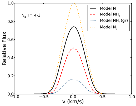
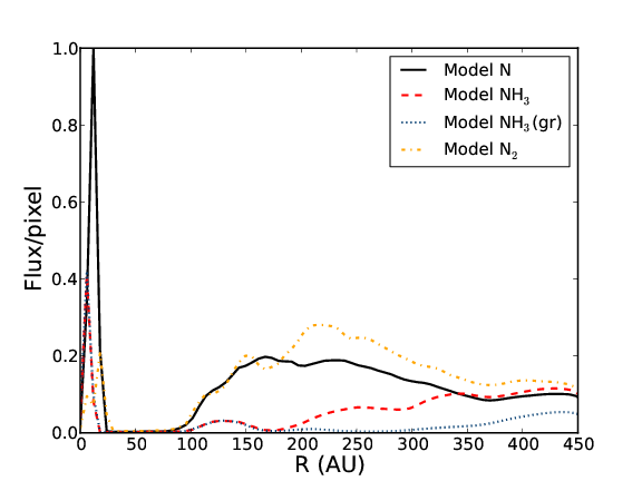
Figure 18 shows the strength of the N2H+ (4-3) line for our four models relative to the strongest line, while Figure 19 shows the average emission as a function of radius. We choose to focus on the relative line strengths because the absolute line strength is highly dependent on the physical model used. The strongest emission is seen in Model N in the inner 25 AU of the disk due to a temporary increase in the local N2H+ abundance. This is a time dependent effect that is also seen in the other models at slightly different times. As such it should not be used as a way to differentiate between the models. The cause is time dependent destruction of reactive molecules with N2H+. These molecules, such as CO and CH4, are depleted in local layers via ionization effects (Bergin et al., 2014).
Beyond = 25 AU the strongest emission is in Model N2. At early times there is less atomic nitrogen available to form NH3 on grains in Model N2 compared to Model N and a larger fraction of the hydrogen goes into the hydrogenation of carbon on grains. With more carbon in CH2 there is less CO available to destroy N2H+, leading to the stronger N2H+ emission in Model N2 beyond AU. Between = 40 AU and = 170 AU the emission in Model N and Model N2 is comparable. The remaining models, Model NH3 and Model NH3(gr), show weaker N2H+ emission overall. While the emission in Model NH3 and Model NH3(gr) is identical inside of = 150 AU, in the outer disk the amount of N2H+ in Model NH3 increases due to the increased presence of N2 while the abundance in Model NH3(gr) remains low. This leads to overall weaker emission in Model NH3(gr). The strongest N2H+ J=4-3 emission in Models N and N2 originates between = 100 AU and = 300 AU in the midplane (Figure 19), resulting in a ring of strong N2H+ emission, similar to that seen in TW Hya (Qi et al., 2013). In Models NH3 and NH3(gr) a similar, though weaker, ring structure is seen beyond = 300 AU.
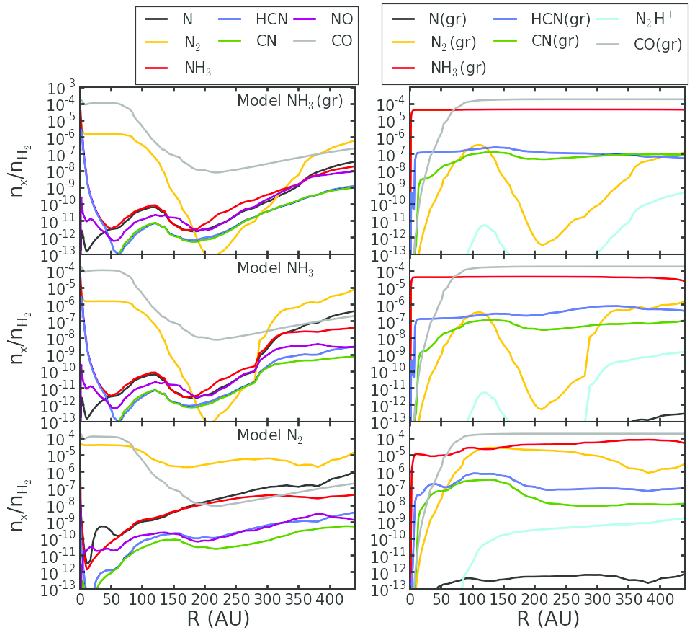
Figure 20 illustrates the midplane abundances in Models NH3, NH3(gr), and N2. Together with Figure 5 they illustrate the gas phase N2 abundance in the N2H+ emission region. In Model N and Model N2, the models with the strongest emission lines, at = 150 AU in the midplane, and . In comparison, for Model NH3 and Model NH3(gr), and . When the gas phase N2 abundance drops below , N2H+ is no longer present. Thus, the strength of the N2H+ line can be used as a proxy for the midplane N2 abundance between 100 and 300 AU for an assumed ionization rate and disk structure. This is entirely consistent with earlier work attempting to determine the N2 abundance from N2H+ in dense cores (Womack et al., 1992). N2H+ has been observed in several disks (Dutrey et al., 2007; Öberg et al., 2010, 2011b). Our models suggest that for N2H+ to be strongly emissive there must be a significant gas phase N2 abundance. It is likely that the mere detection of the N2H+ (4-3) line at the level Jy at 54 pc, e.g. Qi et al. (2013), implies .
The distribution of NO shows some variance between our models. For all of our models it is present in the surface layers. However, in Model NH3(gr) and Model NH3 it is also abundant in the warm molecular layer. Model N, Model NH3(gr) and Model NH3 all show a high NO abundance near the midplane beyond = 300 AU. NO emission in strongest in Model NH3(gr), which has the lowest volatile nitrogen abundances. Thus, detecting NO could indicate a depleted volatile nitrogen reservoir, especially if the N2H+ emission from the source is weak.
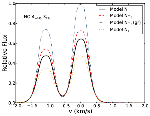
Unfortunately, because NO has an uneven number of electrons ( ground electronic state), strong rotational transitions are replaced by a multitude of weaker lines split by doubling and hyperfine structure that is due to the non-zero spin of the nitrogen atom (Gerin et al., 1992). As a result, detecting NO is extremely difficult. Currently there are no NO detections towards protoplanetary disks, though circumstellar NO has been detected toward the embedded protostar NGC 1333-IRAS 4A (Yıldız et al., 2013) and it has been detected in the dense ISM (McGonagle et al., 1990). However, our models predict the NO () transition (350.68949 GHz) to be on the order of several hundred mJy for a disk 140 pc away (Figure 21). The strongest emission is in Model NH3(gr), with a flux of 437 mJy. For the full ALMA array 4.6 minutes of integration time would be required to detect the strongest of our simulated NO () lines with a 1.4″ beam at the 10 sigma level assuming a spectral resolution of 0.3 km/s. We again note that our models are descriptive of general effects rather than predictive of the overall flux; however, this flux level suggests that NO may be detectable in some systems.
III.4.2 N2H+ as a Probe of the CO Snow Line
N2H+ is used as a tracer of the CO snow line, since gas phase CO destroys N2H+(Qi et al., 2013). Our models support this interpretation (Figures 5 and 20). The decrease in the N2H+ abundance between AU and AU in Models N and N2 corresponds with an increase in the CO gas phase abundance. In Models NH3 and NH3(gr) the midplane N2H+ abundance is much lower. While there is still an increase in the midplane abundance between AU and AU in these models, the mere presence of strong N2H+ emission at the CO snow line suggests that N2 is the main nitrogen reservoir.
III.4.3 Surface Tracers: CN and HCN
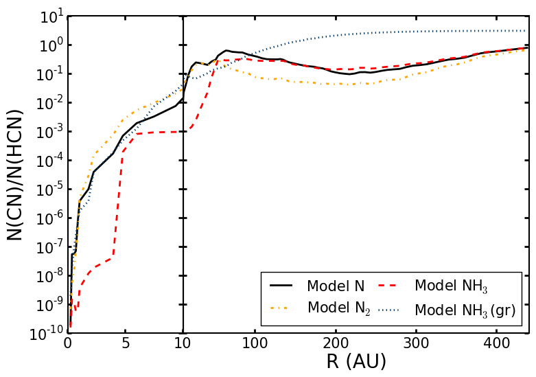
CN and HCN are widely detected in protoplanetary disks (e.g. Chapillon et al., 2012). Figure 22 shows the column density ratio of CN to HCN for our four models. In Model NH3 the ratio is much larger than in the other models inside of 5 AU due to a decrease in the CN column density. Beyond 100 AU the column density of HCN in Model NH3(gr) falls off, resulting in a higher CN/HCN ratio compared to the other models. The ratio of the simulated CN () and HCN (3-2) line strength is 0.5 for Model N. In comparison for most disks with detected CN and HCN emission the ratio is between 1 and 3 (Öberg et al., 2010, 2011b). Our simulated HCN line emission is too strong. This could be due to the specific dust structure used in this model, underestimating the highly uncertain HCN binding energy, or a missing HCN processing mechanism (see discussion in Öberg et al., 2011b).
III.5. Comparison to Cometary Abundances
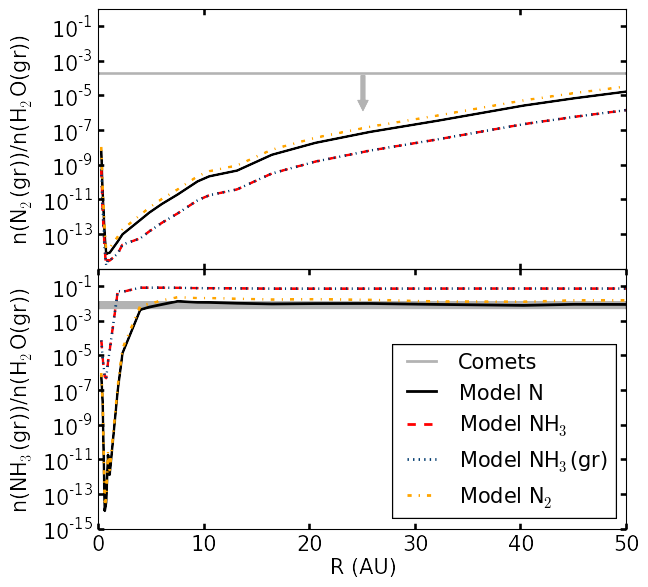
Comets are thought to be indicative of the abundances in the young solar nebula (Bockelée-Morvan, 2011; Caselli & Ceccarelli, 2012). Figure 23 shows how the N2 and NH3 ice abundances in the midplane compare to the observed abundances in comets. The figure shows the inner 50 AU of the disk, where comets are thought to have formed in the solar system (Mumma & Charnley, 2011). The cometary N2 value is an upper limit for Comet Halley (Wyckoff et al., 1991). The NH3 shows the range of values detected in Comet Hale-Bopp, Comet Halley, and Comet Hyakutake (Mumma & Charnley, 2011). The N2 ice abundance relative to water is below the upper limit for Comet Halley in all of our models, with Model N having the highest N2 to water ratio. Though our models are not meant to be analogs for the solar nebula, Model N reproduces the ammonia to water ratio observed in comets, while Model N2 is at the upper limit of the observed range. This suggests either that NH3 is processed into more refractory like material, such as part of CHON dust grains (e.g. Jessberger & Kissel, 1991) or NH3 ice is not as easily incorporated into ices as the models predict. In this case, at face value, these models suggest N was delivered either as N or N2.
IV. Conclusions
We have presented four models for the initial nitrogen abundances in protoplanetary disks. Models in which the majority of the initial nitrogen is in gas phase atomic N predict that N, N2, and NH3 ice are the dominant nitrogen-bearing species at late stages, with a significant fraction of the nitrogen also in HCN ice. When the initial nitrogen is instead placed in N2 gas the differences are difficult to differentiate observationally, indicating that the disk is able to convert gas phase N to N2 efficiently. When the nitrogen starts as NH3, either in the gas phase or frozen onto grains, the majority of the N remains in NH3 ice. Model N best matches the NH3 to H2O ratio in comets, suggesting that N was delivered to the solar nebula in a highly volatile form rather than, for example, in ices.
The presence or absence of N2H+ in the midplane beyond the CO snow line indicates whether nitrogen is dominated by NH3 in the midplane, with the presence of N2H+ correlating with the presence of N2 gas and inversely correlating with the presence of NH3 ice. N2H+ traces the snow line in all four models, though the emission is stronger for Models N and N2. Thus the detection of strong N2H+ emission with a ring-like distribution suggests a disk with a high N2 abundance. In addition, N2H+ emission can be used to determine the gas phase N2 abundance in the midplane. Future sensitive observations of NO and N2H+ combined with disk chemical models will allow us to disentangle the nitrogen history of protoplanetary disks.
Acknowledgments
This work was supported by funding from the National Science Foundation grant AST-1008800 and AST-1344133 (INSPIRE).
References
- Aikawa & Herbst (1999) Aikawa, Y., & Herbst, E. 1999, A&A, 351, 233
- Aikawa et al. (2002) Aikawa, Y., van Zadelhoff, G. J., van Dishoeck, E. F., & Herbst, E. 2002, A&A, 386, 622
- Andrews et al. (2011) Andrews, S. M., Wilner, D. J., Espaillat, C., et al. 2011, ApJ, 732, 42
- Asplund et al. (2009) Asplund, M., Grevesse, N., Sauval, A. J., & Scott, P. 2009, ARA&A, 47, 481
- Benson & Myers (1989) Benson, P. J., & Myers, P. C. 1989, ApJS, 71, 89
- Bergin et al. (2003) Bergin, E., Calvet, N., D’Alessio, P., & Herczeg, G. J. 2003, ApJ, 591, L159
- Bergin et al. (2007) Bergin, E. A., Aikawa, Y., Blake, G. A., & van Dishoeck, E. F. 2007, Protostars and Planets V, 751
- Bergin et al. (2014) Bergin, E. A., Cleeves, L. I., Crockett, N., & Blake, G. 2014, ArXiv e-prints
- Bergin et al. (1995) Bergin, E. A., Langer, W. D., & Goldsmith, P. F. 1995, ApJ, 441, 222
- Bernstein et al. (2002) Bernstein, M. P., Dworkin, J. P., Sandford, S. A., Cooper, G. W., & Allamandola, L. J. 2002, Nature, 416, 401
- Bethell & Bergin (2011a) Bethell, T. J., & Bergin, E. A. 2011a, ApJ, 740, 7
- Bethell & Bergin (2011b) —. 2011b, ApJ, 739, 78
- Bockelée-Morvan (2011) Bockelée-Morvan, D. 2011, in IAU Symposium, Vol. 280, IAU Symposium, ed. J. Cernicharo & R. Bachiller, 261–274
- Brinch & Hogerheijde (2010) Brinch, C., & Hogerheijde, M. R. 2010, A&A, 523, A25
- Caselli & Ceccarelli (2012) Caselli, P., & Ceccarelli, C. 2012, A&A Rev., 20, 56
- Chapillon et al. (2012) Chapillon, E., Guilloteau, S., Dutrey, A., Piétu, V., & Guélin, M. 2012, A&A, 537, A60
- Ciesla & Cuzzi (2007) Ciesla, F. J., & Cuzzi, J. N. 2007, in Lunar and Planetary Inst. Technical Report, Vol. 38, Lunar and Planetary Institute Science Conference Abstracts, 1386
- Cleeves et al. (2013) Cleeves, L. I., Adams, F. C., & Bergin, E. A. 2013, ApJ, 772, 5
- Cleeves et al. (2014) Cleeves, L. I., Bergin, E. A., Alexander, C. M. O., et al. 2014, ArXiv e-prints
- D’Alessio et al. (2006) D’Alessio, P., Calvet, N., Hartmann, L., Franco-Hernández, R., & Servín, H. 2006, ApJ, 638, 314
- Danger et al. (2012) Danger, G., Duvernay, F., Theulé, P., Borget, F., & Chiavassa, T. 2012, ApJ, 756, 11
- Daranlot et al. (2012) Daranlot, J., Hincelin, U., Bergeat, A., et al. 2012, Proceedings of the National Academy of Science, 109, 10233
- Dutrey et al. (2007) Dutrey, A., Henning, T., Guilloteau, S., et al. 2007, A&A, 464, 615
- Dutrey et al. (2014) Dutrey, A., Semenov, D., Chapillon, E., et al. 2014, ArXiv e-prints
- Epstein et al. (1987) Epstein, S., Krishnamurthy, R. V., Cronin, J. R., Pizzarello, S., & Yuen, G. U. 1987, Nature, 326, 477
- Fogel et al. (2011) Fogel, J. K. J., Bethell, T. J., Bergin, E. A., Calvet, N., & Semenov, D. 2011, ApJ, 726, 29
- Furuya & Aikawa (2014) Furuya, K., & Aikawa, Y. 2014, ApJ, 790, 97
- Gerakines et al. (1996) Gerakines, P. A., Schutte, W. A., & Ehrenfreund, P. 1996, A&A, 312, 289
- Gerin et al. (1992) Gerin, M., Viala, Y., Pauzat, F., & Ellinger, Y. 1992, A&A, 266, 463
- Glassgold et al. (1997) Glassgold, A. E., Najita, J., & Igea, J. 1997, ApJ, 480, 344
- Guilloteau et al. (2013) Guilloteau, S., Di Folco, E., Dutrey, A., et al. 2013, A&A, 549, A92
- Harada et al. (2010) Harada, N., Herbst, E., & Wakelam, V. 2010, ApJ, 721, 1570
- Henning & Semenov (2013) Henning, T., & Semenov, D. 2013, Chemical Reviews, 113, 9016
- Herczeg et al. (2002) Herczeg, G. J., Linsky, J. L., Valenti, J. A., Johns-Krull, C. M., & Wood, B. E. 2002, ApJ, 572, 310
- Herczeg et al. (2004) Herczeg, G. J., Wood, B. E., Linsky, J. L., Valenti, J. A., & Johns-Krull, C. M. 2004, ApJ, 607, 369
- Hily-Blant et al. (2010) Hily-Blant, P., Maret, S., Bacmann, A., et al. 2010, A&A, 521, L52
- Hollenbach et al. (2009) Hollenbach, D., Kaufman, M. J., Bergin, E. A., & Melnick, G. J. 2009, ApJ, 690, 1497
- Jessberger & Kissel (1991) Jessberger, E. K., & Kissel, J. 1991, in Astrophysics and Space Science Library, Vol. 167, IAU Colloq. 116: Comets in the post-Halley era, ed. R. L. Newburn, Jr., M. Neugebauer, & J. Rahe, 1075–1092
- Kawakita et al. (2007) Kawakita, H., Jehin, E., Manfroid, J., & Hutsemékers, D. 2007, Icarus, 191, 513
- Le Gal et al. (2014) Le Gal, R., Hily-Blant, P., Faure, A., et al. 2014, A&A, 562, A83
- Mandell et al. (2012) Mandell, A. M., Bast, J., van Dishoeck, E. F., et al. 2012, ApJ, 747, 92
- Maret et al. (2006) Maret, S., Bergin, E. A., & Lada, C. J. 2006, Nature, 442, 425
- Marty (2012) Marty, B. 2012, Earth and Planetary Science Letters, 313, 56
- McElroy et al. (2013) McElroy, D., Walsh, C., Markwick, A. J., et al. 2013, A&A, 550, A36
- McGonagle et al. (1990) McGonagle, D., Irvine, W. M., Minh, Y. C., & Ziurys, L. M. 1990, ApJ, 359, 121
- Mumma & Charnley (2011) Mumma, M. J., & Charnley, S. B. 2011, ARA&A, 49, 471
- Niemann et al. (2005) Niemann, H. B., Atreya, S. K., Bauer, S. J., et al. 2005, Nature, 438, 779
- Öberg et al. (2011a) Öberg, K. I., Boogert, A. C. A., Pontoppidan, K. M., et al. 2011a, ApJ, 740, 109
- Öberg et al. (2005) Öberg, K. I., van Broekhuizen, F., Fraser, H. J., et al. 2005, ApJ, 621, L33
- Öberg et al. (2010) Öberg, K. I., Qi, C., Fogel, J. K. J., et al. 2010, ApJ, 720, 480
- Öberg et al. (2011b) —. 2011b, ApJ, 734, 98
- Owen et al. (2001) Owen, T., Mahaffy, P. R., Niemann, H. B., Atreya, S., & Wong, M. 2001, ApJ, 553, L77
- Pontoppidan et al. (2014) Pontoppidan, K. M., Salyk, C., Bergin, E. A., et al. 2014, ArXiv e-prints
- Qi et al. (2013) Qi, C., Öberg, K. I., Wilner, D. J., et al. 2013, Science, 341, 630
- Roskosz et al. (2013) Roskosz, M., Bouhifd, M. A., Jephcoat, A. P., Marty, B., & Mysen, B. O. 2013, Geochim. Cosmochim. Acta, 121, 15
- Salyk et al. (2011) Salyk, C., Pontoppidan, K. M., Blake, G. A., Najita, J. R., & Carr, J. S. 2011, ApJ, 731, 130
- Sekine et al. (2011) Sekine, Y., Genda, H., Sugita, S., Kadono, T., & Matsui, T. 2011, Nature Geoscience, 4, 359
- Smith et al. (2004) Smith, I. W. M., Herbst, E., & Chang, Q. 2004, MNRAS, 350, 323
- Tafalla et al. (2002) Tafalla, M., Myers, P. C., Caselli, P., Walmsley, C. M., & Comito, C. 2002, ApJ, 569, 815
- Terzieva & Herbst (1998) Terzieva, R., & Herbst, E. 1998, ApJ, 501, 207
- Theule et al. (2011) Theule, P., Borget, F., Mispelaer, F., et al. 2011, A&A, 534, A64
- van der Tak et al. (2007) van der Tak, F. F. S., Black, J. H., Schöier, F. L., Jansen, D. J., & van Dishoeck, E. F. 2007, A&A, 468, 627
- Visser et al. (2011) Visser, R., Doty, S. D., & van Dishoeck, E. F. 2011, A&A, 534, A132
- Waite et al. (2006) Waite, J. H., Combi, M. R., Ip, W.-H., et al. 2006, Science, 311, 1419
- Weidenschilling & Cuzzi (1993) Weidenschilling, S. J., & Cuzzi, J. N. 1993, in Protostars and Planets III, ed. E. H. Levy & J. I. Lunine, 1031–1060
- Womack et al. (1992) Womack, M., Ziurys, L. M., & Wyckoff, S. 1992, ApJ, 393, 188
- Wyckoff et al. (1991) Wyckoff, S., Tegler, S. C., & Engel, L. 1991, ApJ, 367, 641
- Yıldız et al. (2013) Yıldız, U. A., Acharyya, K., Goldsmith, P. F., et al. 2013, A&A, 558, A58


| Assumed EB (K)a | Model N | Model NH3(gr) | Model NH3 | Model N2 | |
|---|---|---|---|---|---|
| N | 800 | 2.250 | 0 | 0 | 0 |
| N2 | 790 | 1.000 | 1.000 | 1.000 | 1.225 |
| CN | 1600 | 6.000 | 6.000 | 6.000 | 6.000 |
| HCN | 2050 | 2.000 | 2.000 | 2.000 | 2.000 |
| NH3 | 3080 | 8.000 | 8.000 | 2.258 | 0 |
| NH3(gr) | 0 | 2.250 | 0 | 0 |