Observation of quantum states without a semiclassical equivalence bound by a magnetic field gradient
Abstract
Resonant transmission through electronic quantum states that exist at the zero points of a magnetic field gradient inside a ballistic quantum wire is reported. Since the semiclassical motion along such a line of zero magnetic field takes place in form of unidirectional snake trajectories, these states have no classical equivalence. The existence of such quantum states has been predicted more than a decade ago by theoretical considerations of Reijniers and coworkers [Reijniers et al., 2002]. We further show how their properties depend on the amplitude of the magnetic field profile as well as on the Fermi energy.
pacs:
73.23.-b,73.21.Nm, 73.20.-rMagnetic field gradients are ubiquitous in science and technology. They are key components of functional units as diverse as, e.g., the Stern-Gerlach setup,Gerlach and Stern (1922) Tokamaks for plasma confinement,Sakharov (1958); Tamm (1958) magnetic resonance imaging,Lauterbur (1973); Garroway et al. (1974) diamagnetic levitation,Berry and Geim (1997) para-hydrogen production,Juarez et al. (2002) or read/write heads of computer hard disks based on the giant magnetoresistance.Baibich et al. (1988); Binasch et al. (1989) In these applications, the magnetic gradient either acts on the electron or nuclear spin, or it affects the dynamics of charged particles, which can be understood within classical pictures. Orbital quantization effects in inhomogeneous magnetic fields have attracted much less attention but may become relevant in some devices as their downsizing continues.
Low-dimensional electron gases in semiconductors are excellent systems for studying such effects, since the electron Fermi energy can be comparable to the magnetic confinement energy, characterized by , where denotes the cyclotron frequency. Furthermore, the electron gases can be exposed to strong magnetic gradients by ferromagnetic Ye et al. (1995) or superconductive Carmona et al. (1995) electrodes. Nogaret (2010) This way, magnetic superlattices Carmona et al. (1995); Ye et al. (1995); Izawa et al. (1995), open magnetic dots Novoselov et al. (2002); Uzur et al. (2004), magnetic stripes which generate electron transport via snake- and cycloid trajectories Nogaret et al. (2000), and magnetic barriers Monzon et al. (1997); Johnson et al. (1997); Kubrak et al. (2000); Vanura et al. (2000); Cerchez et al. (2007); Tarasov et al. (2010) have been implemented. The measured conductance resonances could all be explained in terms of semiclassical trajectories, while suggestions of quantum states in magnetic field gradients without a classical equivalence Reijniers et al. (2002); Xu et al. (2007) have remained unobserved.
Here, we report the observation of the quantum states predicted by Reijniers et al. [Reijniers et al., 2002] to exist at the zero point of a magnetic step from a negative to a positive magnetic field, oriented across a quantum wire. In the original proposal, these states are inaccessible to transport experiments due to diamagnetic shifts of the wire modes in the leads. We overcome this difficulty by using magnetic fields of finite extension in transport direction. After introducing the experimental setup and the sample characterization, we present the experimental results and interpret them with the help of numerical simulations.

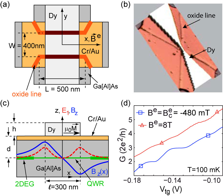
A heterostructure with a two-dimensional electron gas (2DEG) below the surface is used. The 2DEG has an electron density of and a mobility of at liquid helium temperatures. The sample layout is depicted in Fig. 1(a) to (c). A Hall bar with ohmic contacts is patterned into the heterostructure by optical lithography, wet chemical etching and metallization, followed by an alloying step. The ballistic quantum wire (QWR) is defined by scanning probe lithography where the Hall bar surface is oxidized locally, which leads to depletion of the electron gas underneath. Held et al. (1999) Its lithographic length and width are and . The 2DEG to the sides of the QWR can be used as in-plane gates Wieck and Ploog (1990) to fine-tune the Fermi energy locally. The structure is covered by a homogeneous Cr/Au layer of thickness, and a dysprosium (Dy) stripe of width, oriented perpendicular to the wire, is defined on top by electron beam lithography. It has a height of . An external magnetic field magnetizes the stripe along the x-direction. The z-component of the fringe field forms the desired magnetic field gradient in transport direction, with a zero point at x=0. For a magnetic dipole fringe field, in the plane of the 2DEG is given by Vanura et al. (2000)
| (1) |
where denotes the magnetization of the Dy stripe and is the distance of the 2DEG to the bottom of the Dy film. In Fig. 1(c), is plotted for our sample parameters: it corresponds to an approximately constant magnetic gradient in between the edges of the Dy stripe. By Hall magnetometry, Monzon et al. (1997), we estimate the maximum stripe magnetization to ,Sup corresponding to a maximum value of with a maximum gradient of . Within a qualitative picture, predominantly influences QWR mode energies via a local diamagnetic shift, as sketched by the red dashed line in Fig. 1(c). It is assumed that the x - component of the fringe field is irrelevant due to the strong electrostatic confinement in z-direction. Such two magnetic barriers in series of opposite polarity in a QWR have been discussed theoretically,Governale and Boese (2000); Zhai et al. (2002); Papp and Peeters (2010); Xu et al. (2011) in particular as a tunable spin filter,Xu and Okada (2001); Lu et al. (2002); Seo et al. (2004); Jalil (2005); Zhai and Xu (2006) but has so far not been implemented experimentally, while experimental studies of magnetic double barriers in 2DEGs Kubrak et al. (1999); Bae et al. (2007) as well as of single magnetic barriers on QWRs Hugger et al. (2008); Tarasov et al. (2010) have been reported. We have observed the features reported below in two samples and focus below on the data from one sample. For comparative measurements, a second QWR of nominally identical geometry, but without the ferromagnetic stripe, was prepared on a different piece of the same heterostructure.
Measurements at temperatures were performed in a gas flow cryostat using standard lock-in techniques, while for , a dilution refrigerator was used. Both systems are equipped with a superconductive magnet and a rotating sample stage that allows to tune the QWR from perpendicular to parallel orientation with respect to . Parallel alignment is achieved by adjusting the Hall resistance to zero.
In Fig. 1 (d), the conductance of the QWR as a function of the top gate voltage at the coercive magnetic field of the Dy stripe, is shown. We estimate the electron temperature to . Well-developed conductance plateaus with quantized values of are observed for =2 and 3.van Wees et al. (1988a); Wharam et al. (1988) The plateau for (not shown) is weakly pronounced, which may be a consequence of the greatly decreased electron density in the 2DEG reservoirs, and the visibility of the j=4 plateau is low. In , the conductance is shifted towards larger values. We attribute this shift to the magnetic barrier fields , which suppresses backscattering at the entrance and the exit of the QWR. van Houten et al. (1988) This appears plausible considering that our reference QWR without a Dy stripe on top shows, in the regime of six occupied modes at , a positive magnetoconductance of about as the homogeneous perpendicular magnetic field is increased from to .Sup In addition, the plateaus tend to get suppressed, and the different, weak modulation of the conductance traces can not be assigned to the number of occupied modes. This is different as compared to homogeneous magnetic fields, which are known to increase the markedness of the conductance plateaus.van Wees et al. (1988b) We can exclude spin splitting as possible origin, since measurements on the nominally identical QWR without a Dy stripe on top did not show signatures of spin splitting up to , Sup indicative of a small effective g factor in our QWRs, which may be due to screening by the homogeneous Cr/Au top gate. We therefore attribute the suppression of the conductance quantization and the emergence of additional features to the magnetic field profile .

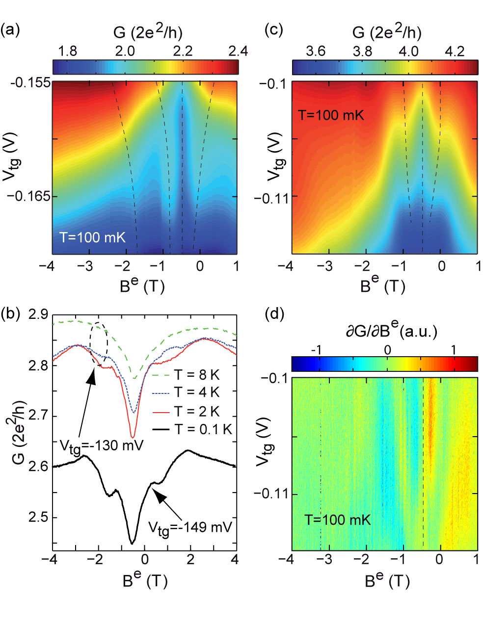
Fig. 2 (a) shows the magnetoconductance of the QWR as a function of and of the top gate voltage in the gate voltage interval where two modes are occupied. In all measurements shown, the voltage applied to the two in-plane gates was . As a general trend, the conductance increases as is increased, which we attribute to the changing local magnetic field at the entrance and exit as mentioned above. Superimposed conductance peaks are visible at distances to which increase as is increased, as indicated by the dashed lines. In a different cooldown of the same sample in the gas flow cryostat, the same structures are observed, which disappear at a temperature of , see Fig. 2 (b). We can therefore exclude that the resonances are of classical origin.
The features are less pronounced around plateaus 3 to 7, as exemplified for the fourth plateau in Fig. 2 (c). In order to increase the visibility of resonances, we show in Fig. 2 (d) the numerical derivative of the data of (c). It can be seen that the resonance closest to shifts from at to at . Furthermore, these features are observed as a function of both the top gate and the in-plane gate voltages,Sup indicating again that they originate from inside the QWR rather than from some scattering centers in the 2DEG.
We therefore attribute the conductance resonances to discrete states inside the QWR that form in the presence of the magnetic field profile . They are interpreted with the help of numerical simulations, which are based on a combination of the tight-binding model with recursive Green functions. Xu et al. (2007, 2011) The parameters used in the simulation are adapted to our sample, with the exception that and that due to numerical limitations, the quantum wire (electronic width ) is directly attached to reservoirs, such that the transition from the QWR to the 2DEG is not captured. Since the oxide lines written by scanning probe lithography are known to generate superparabolic confinement, Fuhrer et al. (2001) hard walls are assumed. The wire is exposed to the profile given by eq. (1) with a barrier spacing of and an amplitude parameterized by the magnetization . All calculations have been carried out for zero temperature.
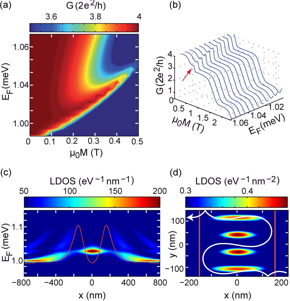
We first focus on a clear-cut situation, as found at relatively large Fermi energies where four modes are occupied for , corresponding to Fig. 2 (c,d). In Fig. 3 (a), the calculated conductance as a function of and is shown. The QWR modes get depopulated locally as either is decreased or is increased. In the transition region between plateau 3 and 4, a conductance resonance is observed which shifts to larger magnetization as is increased, in qualitative agreement with the experimental results. Its amplitude depends sensitively on the parameters as well as on the conductance plateau considered, as illustrated by the calculated conductance over a larger range of magnetizations shown in Fig. 3 (b), where one resonance between plateau 3 and 4 is visible, but none between plateau 2 and 3.

The origin of such resonances are bound states at the zero point of at , which becomes apparent with the help of the local density of states (LDOS). In Fig. 3 (c), the LDOS as a function of x and the Fermi energy, integrated along the y-direction, is shown for a ferromagnetic stripe magnetization of , which is a plausible magnetization for . Sup The x-dependent energy of the modes is represented by the red line. Its maxima correspond to the centers of the two magnetic barriers. A zero-dimensional state at emerges. The LDOS of this zero-dimensional state at as a function of x and y is shown in Fig. 3 (d). It has the character of a standing wave in transverse direction, and the number of nodes indicates that it originates from the fourth wire mode.

This state has the same structure as those residing at the zero point of an infinitely sharp magnetic step , studied theoretically by Reijniers et al. [Reijniers et al., 2002], where denotes the Heaviside step function and is the step height. As pointed out there, this state does not have a semiclassical equivalence, since classically, only a unidirectional snake type orbit exists at such a step. This is exemplified by one calculated trajectory, shown in Fig. 3 (d). A quantum calculation of the energy dispersion however shows that states do exist with a group velocity of opposite polarity to that one of the classical snake orbit, such that a standing wave can be formed. Our experimental implementation of this structure deviates in some respects from the infinitely sharp step. First of all, the sharp step corresponds to a constant diamagnetic shift along the QWR, except at where the shift is zero. Consequently, the effective confinement has the character of a -potential and only one bound state per mode in the x-direction exists. However, in our implementation, the magnetic field gradient is finite and the effective confinement in x-direction is softer, such that several states along the x-direction become possible. Also, a striking paramagnetic shift of the bound states is found in Ref. [Reijniers et al., 2002], which reflects their increasing localization at the magnetic step as is increased. For our magnetic field profile, however, the effective potential becomes narrower as the magnetization increases, which causes the energies of the states to increase with increasing magnetization. Furthermore, we note that for the parameters considered here, all occupied modes contribute to the conductance at the Fermi level, but only the uppermost mode forms zero-dimensional states. We therefore expect that the transmission has the character of a Fano resonance,Fano (1961); Xu et al. (2011) and that the LDOS contains admixtures of the propagating states belonging to lower lying modes. Within our implementation of the numerical algorithms, it is not possible to decompose the LDOS into contributions by different modes. A Fano character of the resonances should moreover also show up in their line shape. Due to the strongly varying background, however, such fits to our measured resonances are questionable.
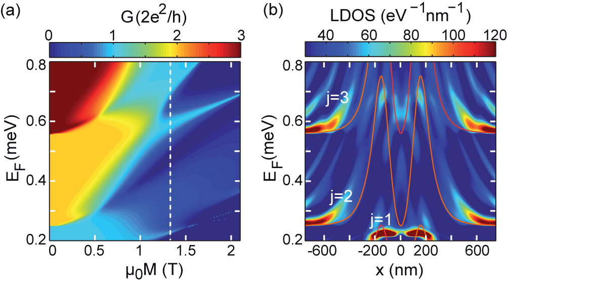
The consequences of the deviations of our experimental implementation to the ideal magnetic step in a QWR are illustrated in Fig. 4, where the conductance over a wide range of Fermi energies and magnetizations is shown. As the magnetization increases, the weakly pronounced conductance modulations evolve into sharp resonances, reflecting the increased effective confinement, see Fig. 4(a). Furthermore, a second resonance per QWR mode can be formed. This can be seen, for example, in the conductance as a function of for , or as a function of at . For the latter case, we show the LDOS () in Fig. 4(b). Here, two LDOS maxima at and are visible, both belonging to the third QWR mode. Note that the bound state with larger energy shows a node in the x-direction at . This energy structure reflects the facts that in our sample, the steepness of our magnetic step is finite and that the confinement in the x-direction is weaker than in the y-direction.
To summarize, we have observed resonant transmission through a ballistic quantum wire via hitherto unobserved magnetically bound states that reside at the zero point of a magnetic field gradient, as suggested by Reijniers et al. [Reijniers et al., 2002] These quantum states have no classical equivalence. We observe up to two such states per wire mode, all with a diamagnetic response. Both of these features are in contrast to the original proposal and we have explained them by the finite steepness of the magnetic step in our experimental implementation. The presence of several bound states per mode is also of relevance regarding an experimental realization of the suggested magnetic barrier spin filters, Lu et al. (2002); Seo et al. (2004); Jalil (2005); Zhai and Xu (2006) since their energy spacing may be comparable to the spin splitting energy and thereby influence the achievable degree of spin polarization.
The authors would like to thank HHU Düsseldorf for financial support and I. V. Zozoulenko for valuable discussions in relation to the Green function formalism. ADW is grateful to the DFH/UFA for support in the CDFA-05-06.
References
- Reijniers et al. (2002) J. Reijniers, A. Matulis, K. Chang, F. M. Peeters, and P. Vasilopoulos, Europhys. Lett. 59, 749 (2002).
- Gerlach and Stern (1922) W. Gerlach and O. Stern, Z. Phys. 9, 349 (1922).
- Sakharov (1958) A. D. Sakharov, Plasma Physics and the Problem of Controlled Thermonuclear Reactions 1, 20 (1958).
- Tamm (1958) I. E. Tamm, Plasma Physics and the Problem of Controlled Thermonuclear Reactions 1, 3 (1958).
- Lauterbur (1973) P. C. Lauterbur, Nature 242, 190 (1973).
- Garroway et al. (1974) A. N. Garroway, P. K. Grannell, and P. Mansfield, J. Phys. C 7, L457 (1974).
- Berry and Geim (1997) M. V. Berry and A. K. Geim, Eur. J. Phys. 18, 307 (1997).
- Juarez et al. (2002) A. M. Juarez, D. Cubric, and G. C. King, Meas. Sci. Technol. 13, N52 (2002).
- Baibich et al. (1988) M. N. Baibich, J. M. Broto, A. Fert, V. D. Nguyen, F. Petroff, P. Etienne, G. Creuset, A. Friedrich, and J. Chazelas, Phys. Rev. Lett. 61, 2472 (1988).
- Binasch et al. (1989) G. Binasch, P. Grnberg, F. Saurenbach, and W. Zinn, Phys. Rev. B 39, 4828 (1989).
- Ye et al. (1995) P. D. Ye, D. Weiss, R. R. Gerhardts, M. Seeger, K. von Klitzing, K. Eberl, and H. Nickel, Phys. Rev. Lett. 74, 3013 (1995).
- Carmona et al. (1995) H. A. Carmona, A. K. Geim, A. Nogaret, P. C. Main, T. J. Foster, M. Henini, and S. P. B. M. G. Blamire, Phys. Rev. Lett. 74, 3009 (1995).
- Nogaret (2010) A. Nogaret, J. Phys. Cond. Mat. 22, 253201 (2010).
- Izawa et al. (1995) S. Izawa, S. Katsumoto, A. Endo, and Y. Iye, J. Phys. Soc. Jpn. 64, 706 (1995).
- Novoselov et al. (2002) K. S. Novoselov, A. K. Geim, S. V. Dubonos, Y. G. Cornelissens, F. M. Peeters, and J. C. Maan, Phys. Rev. B 65, 233312 (2002).
- Uzur et al. (2004) D. Uzur, A. Nogaret, H. E. Beere, D. A. Ritchie, C. H. Marrows, and B. J. Hickey, Phys. Rev. B 69, 241301 (2004).
- Nogaret et al. (2000) A. Nogaret, S. J. Bending, and M. Henini, Phys. Rev. Lett. 84, 2231 (2000).
- Monzon et al. (1997) F. G. Monzon, M. Johnson, and M. L. Roukes, Appl. Phys. Lett. 71, 3087 (1997).
- Johnson et al. (1997) M. Johnson, B. R. Bennett, M. J. Yang, M. M. Miller, and B. V. Shanabrook, Appl. Phys. Lett. 71, 974 (1997).
- Kubrak et al. (2000) V. Kubrak, A. Neumann, B. L. Gallagher, P. C. Main, M. Henini, C. H. Marrows, and B. J. Hickey, J. Appl. Phys. 87, 5986 (2000).
- Vanura et al. (2000) T. Vanura, T. Ihn, S. Broderick, K. Ensslin, W. Wegscheider, and M. Bichler, Phys. Rev. B 62, 5074 (2000).
- Cerchez et al. (2007) M. Cerchez, S. Hugger, T. Heinzel, and N. Schulz, Phys. Rev. B 75, 035341 (2007).
- Tarasov et al. (2010) A. Tarasov, S. Hugger, H. Xu, M. Cerchez, T. Heinzel, I. V. Zozoulenko, U. Gasser-Szerer, D. Reuter, and A. D. Wieck, Phys. Rev. Lett. 104, 186801 (2010).
- Xu et al. (2007) H. Xu, T. Heinzel, M. Evaldsson, S. Ihnatsenka, and I. V. Zozoulenko, Phys. Rev. B 75, 205301 (2007).
- Held et al. (1999) R. Held, S. Lscher, T. Heinzel, K. Ensslin, and W. Wegscheider, Appl. Phys. Lett. 75, 1134 (1999).
- Wieck and Ploog (1990) A. D. Wieck and K. Ploog, Appl. Phys. Lett. 56, 928 (1990).
- (27) See Supplemental Material at [URL will be inserted by publisher] for details.
- Governale and Boese (2000) M. Governale and D. Boese, Appl. Phys. Lett. 77, 3215 (2000).
- Zhai et al. (2002) F. Zhai, Y. Guo, and B.-L. Gu, Phys. Rev. B 66, 125305 (2002).
- Papp and Peeters (2010) G. Papp and F. M. Peeters, J. Appl. Phys. 107, 063718 (2010).
- Xu et al. (2011) H. Xu, T. Heinzel, and I. V. Zozoulenko, Phys. Rev. B 84, 035319 (2011).
- Xu and Okada (2001) H. Z. Xu and Y. Okada, Appl. Phys. Lett. 79, 3119 (2001).
- Lu et al. (2002) M.-W. Lu, L.-D. Zhang, and X.-H. Yan, Phys. Rev. B 66, 224412 (2002).
- Seo et al. (2004) K. C. Seo, G. Ihm, K.-H. Ahn, and S. J. Lee, J. Appl. Phys. 95, 7252 (2004).
- Jalil (2005) M. B. A. Jalil, J. Appl. Phys. 97, 024507 (2005).
- Zhai and Xu (2006) F. Zhai and H. Q. Xu, Appl. Phys. Lett. 88, 032502 (2006).
- Kubrak et al. (1999) V. Kubrak, F. Rahman, B. L. Gallagher, P. C. Main, M. Henini, C. H. Marrows, and M. A. Howson, Appl. Phys. Lett. 74, 2507 (1999).
- Bae et al. (2007) J. U. Bae, T. Y. Lin, Y. Yoon, S. J. Kim, J. P. Bird, A. Imre, W. Porod, and J. L. Reno, Appl. Phys. Lett. 91, 022105 (2007).
- Hugger et al. (2008) S. Hugger, H. Xu, A. Tarasov, M. Cerchez, T. Heinzel, I. V. Zozoulenko, D. Reuter, and A. D. Wieck, Phys. Rev. B 78, 165307 (2008).
- van Wees et al. (1988a) B. J. van Wees, H. van Houten, C. W. J. Beenakker, J. G. Williamson, L. P. Kouwenhoven, D. van der Marel, and C. T. Foxon, Phys. Rev. Lett. 60, 848 (1988a).
- Wharam et al. (1988) D. A. Wharam, T. J. Thornton, R. Newbury, M. Pepper, H. Ahmed, J. E. F. Frost, D. G. Hasko, D. C. Peacock, D. A. Ritchie, and G. A. C. Jones, J. Phys. C 21, L209 (1988).
- van Houten et al. (1988) H. van Houten, C. W. J. Beenakker, P. H. M. van Loosdrecht, T. J. Thornton, H. Ahmed, M. Pepper, C. T. Foxon, and J. J. Harris, Phys. Rev. B 37, 8534 (1988).
- van Wees et al. (1988b) B. J. van Wees, L. P. Kouwenhoven, H. van Houten, C. W. J. Beenakker, J. E. Mooij, C. T. Foxon, and J. J. Harris, Phys. Rev. B 38, 3625 (1988b).
- Fuhrer et al. (2001) A. Fuhrer, S. Lscher, T. Heinzel, K. Ensslin, W. Wegscheider, and M. Bichler, Phys. Rev. B 63, 125309 (2001).
- Fano (1961) U. Fano, Phys. Rev. 124, 1866 (1961).