\OAGMarXiv

1404.3538

Sinogram constrained TV-minimization for metal artifact reduction in CT

Clemens Schiffer and Kristian Bredies Institute for Mathematics and Scientific Computing, University of Graz, Heinrichstraße 36, A-8010 Graz, Austria (clemens.schiffer@edu.uni-graz.at)Institute for Mathematics and Scientific Computing, University of Graz, Heinrichstraße 36, A-8010 Graz, Austria (kristian.bredies@uni-graz.at)
Abstract

A new method for reducing metal artifacts in X-ray computed tomography (CT) images is presented. It bases on the solution of a convex optimization problem with inequality constraints on the sinogram, and total variation regularization for the reconstructed image. The Chambolle-Pock algorithm is used to numerically solve the discretized version of the optimization problem. As proof of concept we present and discuss numerical results for synthetic data.

1 Introduction

X-ray computed tomography (CT) has become a major tool in medical imaging, yet metal inclusions in the patient, such as pacemakers, screws, orthopedic implants and dental fillings, still pose a problem. The basic principle of CT is rotating an X-ray source and an opposing detector around the object to be scanned, producing projection data from a range of angles. These projections of intensities, known as the sinogram, have to be reconstructed into a spatial image, in order to obtain the desired cross-section. To achieve this, the standard method is filtered back projection (FBP), which works very well under ideal or even normal circumstances. Still errors from various sources, such as patient movement, beam scatter etc. disturb this reconstruction process and lead to artifacts. In particular, the presence of metal inclusions produces significant dark and bright smears, known as metal artifacts, that may render the image unusable for diagnostics.

Existing techniques for reducing metal artifacts can be categorized into technical enhancements and computational methods. The former include the use of dual energy CT devices [1], which feature two sources that produce projections from different angles. The different energy levels used by the two sources allow to identify a substance by their specific absorption spectrum, this information can then be used to reduce metal artifacts. In contrast, computational methods focus on processing the already collected data in a way that removes the artifacts. This is, for instance, accomplished by replacing the corrupted data either in the spatial or the projection domain, e. g., by interpolation [10] or inpainting [5], with various refinements such as repeated projection, back-projection and replacement of bad data [2, 7]. Variational methods involving total variation regularization have been proposed [8], and applied with the recently developed Chambolle-Pock algorithm  [9]. The novelty of our method lies in the dedicated treatment of metal artifacts by introducing pointwise inequality constraints on the sinogram in addition to total variation regularization of the image.

In Section 2 the problem is presented and mathematically modeled, in Section 3 the numerical solution is discussed and an algorithm for solving the proposed optimization problem is described, in Section 4 results are presented and, finally, in Section 5, a conclusion is given.

2 Problem and Mathematical Model

The object to be scanned is modeled as a continuous function f(x,y)𝑓𝑥𝑦f(x,y) in 2superscript2\mathbb{R}^{2}, that represents the density of the object at a point (x,y)𝑥𝑦(x,y). It is assumed to be zero outside a region of interest. The assumption of the model is that the attenuation an X-ray suffers, i. e. the loss of intensity, is proportional to the traversed density. Therefore, the process of an X-ray passing through the object, being weakened and received by a detector is modeled as integrating f𝑓f over a straight line L𝐿L

(Af)(φ,s)=Lf(x)𝑑s,𝐴𝑓𝜑𝑠subscript𝐿𝑓𝑥differential-d𝑠\displaystyle(Af)(\varphi,s)=\int_{L}f(x)ds, (1)

where φ𝜑\varphi is the gradient angle of L𝐿L and s𝑠s its signed distance from the origin, the offset. This is called the Radon transform and the data it produces a sinogram, which is commonly interpreted as a function of angle and offset. Consider a ray that starts at the source with intensity I(xS)𝐼subscript𝑥𝑆I(x_{S}) and whose intensity is measured at the detector giving I(xD)𝐼subscript𝑥𝐷I(x_{D}). By the modeling assumption [6] we get

(Af)(φ,s)=Lf(x)𝑑s=log(I(xD))+log(I(xS)).𝐴𝑓𝜑𝑠subscript𝐿𝑓𝑥differential-d𝑠𝐼subscript𝑥𝐷𝐼subscript𝑥𝑆\displaystyle(Af)(\varphi,s)=\int_{L}f(x)ds=-\log(I(x_{D}))+\log(I(x_{S})). (2)

Now if the ray passes through a very dense area, and is attenuated so strongly that the detector cannot differentiate its signal from noise, i. e. the received signal is unknown but lower than a certain threshold ε𝜀\varepsilon, then I(xD)<ε𝐼subscript𝑥𝐷𝜀I(x_{D})<\varepsilon. The intensity at the source I(xS)𝐼subscript𝑥𝑆I(x_{S}) is considered constant, and therefore, we get (Af)(φ,s)>log(ε)+log(I(xS))=:C(Af)(\varphi,s)>-\log(\varepsilon)+\log(I(x_{S}))=\colon C. Thus, this process of beam cancellation is represented by “capping” the sinogram, i. e. defining a certain threshold C𝐶C and considering the values for each point in the sinogram that exceeds C𝐶C as unknown, but at least as great as the threshold. The domain of the sinogram is denoted as ΩΩ\Omega, while the portion where the threshold is exceeded is denoted as Ω0subscriptΩ0\Omega_{0}. The capped sinogram is called U0subscript𝑈0U_{0} and considered to be the given data. It is assumed - as in total variation denoising - that f𝑓f has a certain spatial structure for the propose of this paper it is assumed to be piecewise constant and therefore to admit a low total variation semi-norm. In trying to reconstruct f𝑓f we therefore look for an approximation u𝑢u that has also low TV-norm and for which an application of the Radon transform will produce a sinogram that is similar to that of f𝑓f in ΩΩ0ΩsubscriptΩ0\Omega\setminus\Omega_{0} and also has values greater or equal than C𝐶C in Ω0subscriptΩ0\Omega_{0}. This leads to the optimization problem

{minuX12AuU02+λu1s.t. AuΩ0Ccasessubscript𝑢𝑋12superscriptdelimited-∥∥𝐴𝑢subscript𝑈02𝜆subscriptdelimited-∥∥𝑢1otherwiseevaluated-ats.t. 𝐴𝑢subscriptΩ0𝐶otherwise\displaystyle\begin{cases}\min_{u\in X}\quad\frac{1}{2}\lVert Au-U_{0}\rVert^{2}+\lambda\lVert\nabla u\rVert_{1}\\ \text{s.t. }Au\mid_{\Omega_{0}}\geq C\end{cases} (3)

where =L2(ΩΩ0)delimited-∥∥subscriptdelimited-∥∥superscript𝐿2ΩsubscriptΩ0\lVert\cdot\rVert=\lVert\cdot\rVert_{L^{2}(\Omega\setminus\Omega_{0})} and 1=L1(Ω)2subscriptdelimited-∥∥1subscriptsuperscriptdelimited-∥∥2superscript𝐿1Ω\lVert\cdot\rVert_{1}=\lVert\cdot\rVert^{2}_{L^{1}(\Omega)}. Here λ>0𝜆0\lambda>0 serves as a balancing parameter between regularization via the total variation semi-norm, and the discrepancy between Au𝐴𝑢Au and U0subscript𝑈0U_{0}, which is measured on ΩΩ0ΩsubscriptΩ0\Omega\setminus\Omega_{0} i. e. only on sinogram data that is considered to be correct. Using the indicator function

IM(x)={0,if xM,if xMsubscript𝐼𝑀𝑥cases0if 𝑥𝑀if 𝑥𝑀\displaystyle I_{M}(x)=\begin{cases}0,&\text{if }x\in M\\ \infty,&\text{if }x\notin M\\ \end{cases} (4)

where 0=0000\cdot\infty=0 and 1=11\cdot\infty=\infty are set, we can reformulate (3) as

minuX12AuU02+λu1+I{AuΩ0C}(u).subscript𝑢𝑋12superscriptdelimited-∥∥𝐴𝑢subscript𝑈02𝜆subscriptdelimited-∥∥𝑢1subscript𝐼evaluated-at𝐴𝑢subscriptΩ0𝐶𝑢\displaystyle\min_{u\in X}\quad\frac{1}{2}\lVert Au-U_{0}\rVert^{2}+\lambda\lVert\nabla u\rVert_{1}+I_{\{Au\mid_{\Omega_{0}}\geq C\}}(u). (5)

The parameter λ𝜆\lambda is not needed if one enforces Au=U0𝐴𝑢subscript𝑈0Au=U_{0} in ΩΩ0ΩsubscriptΩ0\Omega\setminus\Omega_{0} as a hard constraint. Then, the minimization problem becomes

{minuXu1s.t. AuΩ0CAuΩΩ0=U0casessubscript𝑢𝑋subscriptdelimited-∥∥𝑢1otherwiseevaluated-ats.t. 𝐴𝑢subscriptΩ0𝐶evaluated-at𝐴𝑢ΩsubscriptΩ0subscript𝑈0otherwise\displaystyle\begin{cases}\min_{\begin{subarray}{c}u\in X\end{subarray}}\quad\lVert\nabla u\rVert_{1}\\ \text{s.t. }Au\mid_{\Omega_{0}}\geq C\wedge Au\mid_{\Omega\setminus\Omega_{0}}=U_{0}\end{cases} (6)

which is equivalent to

minuXu1+I{AuΩ0C}(u)+I{AuΩΩ0=U0}(u).subscript𝑢𝑋subscriptdelimited-∥∥𝑢1subscript𝐼evaluated-at𝐴𝑢subscriptΩ0𝐶𝑢subscript𝐼evaluated-at𝐴𝑢ΩsubscriptΩ0subscript𝑈0𝑢\displaystyle\min_{\begin{subarray}{c}u\in X\end{subarray}}\quad\lVert\nabla u\rVert_{1}+I_{\{Au\mid_{\Omega_{0}}\geq C\}}(u)+I_{\{Au\mid_{\Omega\setminus\Omega_{0}}=U_{0}\}}(u). (7)
Refer to caption
(a)
Refer to caption
(b)

\rightarrow

Refer to caption
(c)
Refer to caption
(d)
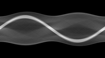
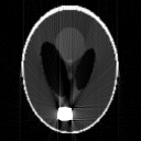
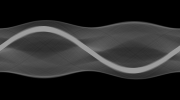
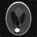
Figure 1: Metal artifacts are simulated with a synthetic test image. 1(a) shows a Shepp-Logan phantom, with values in [0,1]01[0,1] to which a block of value 3 has been added, simulating metal. 1(b) shows the result of applying the Radon transform, i. e. the corresponding sinogram. In 1(d), this sinogram has been capped: values greater than 454545 have been set to 454545, 1(c) shows the devastating results of simply applying the MATLAB-function iradon to the capped sinogram. Figures 1(a) and 1(c) display only values in [0,1]01[0,1] for better contrast.

\leftarrow

3 Numerical Solution

We are numerically solving a discretized version of (5) and (7), following the presentation in [3]. In order to discretize the gradient \nabla a finite difference scheme with spacing hh and zero boundary extension is used. Note that then, h2<8h2superscriptdelimited-∥∥subscript28superscript2\lVert\nabla_{h}\rVert^{2}<\frac{8}{h^{2}} and its adjoint is h=divhsuperscriptsubscriptsubscriptdiv\nabla_{h}^{\ast}=-\operatorname{div}_{h} with a similar discretization. The discretization of the Radon transform Ahsubscript𝐴A_{h} is implemented as follows: Every point in the image domain is, for each of the N𝑁N angles, projected onto the detector line, which is separated into M𝑀M bins. The value at the point is then assigned proportionally to the two bins the point is projected inbetween. This implementation yields the same results as the MATLAB-function radon, when using 2×2222\times 2 oversampling. The adjoint of the discrete Radon transform Ahsuperscriptsubscript𝐴A_{h}^{\ast} is a discretization of the linear back projection, which is implemented similarly, each point in the image domain is projected onto the detector line and linear interpolation is performed. Then the values for all angles are summed up. Numerical tests confirm that this implementation provides the adjoint to the discrete Radon transform.

The optimization problems (5) and (7) are of the form

minuXF(u)+G(Ku),subscript𝑢𝑋𝐹𝑢𝐺𝐾𝑢\min_{u\in X}F(u)+G(Ku), (8)

with F:X,G:Y:𝐹𝑋𝐺:𝑌F\colon X\rightarrow\mathbb{R},G\colon Y\rightarrow\mathbb{R} convex, lower semi-continuous and proper, as well as K:XY:𝐾𝑋𝑌K\colon X\rightarrow Y linear and continuous. These problems satisfy the sufficient conditions for the Fenchel-Rockafellar duality [3]. The dual problem reads as

maxwYF(Kw)G(w).subscript𝑤superscript𝑌superscript𝐹superscript𝐾𝑤superscript𝐺𝑤\displaystyle\max_{w\in Y^{\ast}}-F^{\ast}(-K^{\ast}w)-G^{\ast}(w). (9)

Now, solving the primal and dual equation simultaneously can be interpreted as finding the saddle-point of the function

L(u,w)=w,Ku+F(u)G(w).𝐿𝑢𝑤𝑤𝐾𝑢𝐹𝑢superscript𝐺𝑤\displaystyle L(u,w)=\langle w,Ku\rangle+F(u)-G^{\ast}(w). (10)

In order to solve this problem, the Chambolle-Pock algorithm [4]

{wk+1=(id+τG)1(wk+τKu¯k)uk+1=(id+σF)1(ukσKwk+1)u¯n+1=2uk+1ukcasessuperscript𝑤𝑘1superscript𝑖𝑑𝜏superscript𝐺1superscript𝑤𝑘𝜏𝐾superscript¯𝑢𝑘otherwisesuperscript𝑢𝑘1superscript𝑖𝑑𝜎𝐹1superscript𝑢𝑘𝜎superscript𝐾superscript𝑤𝑘1otherwisesuperscript¯𝑢𝑛12superscript𝑢𝑘1superscript𝑢𝑘otherwise\displaystyle\begin{cases}w^{k+1}=(id+\tau\partial G^{\ast})^{-1}(w^{k}+\tau K\bar{u}^{k})\\ u^{k+1}=(id+\sigma\partial F)^{-1}(u^{k}-\sigma K^{\ast}w^{k+1})\\ \bar{u}^{n+1}=2u^{k+1}-u^{k}\end{cases} (11)

is employed, which converges to a saddle point of (10), if στK2<1𝜎𝜏superscriptdelimited-∥∥𝐾21\sigma\tau\lVert K\rVert^{2}<1. In order to match the form of (8), the following discrete version of (3)

minun×m12AhuU02+λhu1+I{AhuΩ0C}(u)subscript𝑢superscript𝑛𝑚12superscriptdelimited-∥∥subscript𝐴𝑢subscript𝑈02𝜆subscriptdelimited-∥∥subscript𝑢1subscript𝐼evaluated-atsubscript𝐴𝑢subscriptΩ0𝐶𝑢\displaystyle\min_{u\in\mathbb{R}^{n\times m}}\quad\frac{1}{2}\lVert A_{h}u-U_{0}\rVert^{2}+\lambda\lVert\nabla_{h}u\rVert_{1}+I_{\{A_{h}u\mid_{\Omega_{0}}\geq C\}}(u) (12)

is dualized with F=0𝐹0F=0 and G:N×M×n×m×2:𝐺superscript𝑁𝑀superscript𝑛𝑚2subscriptG\colon\mathbb{R}^{N\times M}\times\mathbb{R}^{n\times m\times 2}\rightarrow\mathbb{R}_{\infty} as well as the linear mapping K:m×nM×N×m×n×2:𝐾superscript𝑚𝑛superscript𝑀𝑁superscript𝑚𝑛2K\colon\mathbb{R}^{m\times n}\rightarrow\mathbb{R}^{M\times N}\times\mathbb{R}^{m\times n\times 2} defined by

G(x,y)=12xU02+I{xΩ0C}(x)+λy1K=[Ahh].formulae-sequence𝐺𝑥𝑦12superscriptdelimited-∥∥𝑥subscript𝑈02subscript𝐼evaluated-at𝑥subscriptΩ0𝐶𝑥𝜆subscriptdelimited-∥∥𝑦1𝐾matrixsubscript𝐴subscript\displaystyle G(x,y)=\frac{1}{2}\lVert x-U_{0}\rVert^{2}+I_{\{x\mid_{\Omega_{0}}\geq C\}}(x)+\lambda\lVert y\rVert_{1}\qquad K=\begin{bmatrix}A_{h}\\ \nabla_{h}\end{bmatrix}. (13)

For F=0𝐹0F=0 the resolvent is (id+σF)1=idsuperscript𝑖𝑑𝜎𝐹1𝑖𝑑(id+\sigma\partial F)^{-1}=id, as for Gsuperscript𝐺G^{\ast} its resolvent can be evaluated componentwise, i. e. for G(x,y)=G1(x)+G2(y)𝐺𝑥𝑦subscript𝐺1𝑥subscript𝐺2𝑦G(x,y)=G_{1}(x)+G_{2}(y) we have

(id+σG)1(v¯,w¯)=((id+σG1)1(v¯)(id+σG2)1(w¯))superscript𝑖𝑑𝜎superscript𝐺1¯𝑣¯𝑤matrixsuperscript𝑖𝑑𝜎subscriptsuperscript𝐺11¯𝑣superscript𝑖𝑑𝜎subscriptsuperscript𝐺21¯𝑤\displaystyle(id+\sigma\partial G^{\ast})^{-1}(\bar{v},\bar{w})=\begin{pmatrix}(id+\sigma\partial G^{\ast}_{1})^{-1}(\bar{v})\\ (id+\sigma\partial G^{\ast}_{2})^{-1}(\bar{w})\end{pmatrix} (14)

As G1(x)=(i,j)ΩΩ0(xU0)i,j2+(i,j)Ω0IxC(xi,j)subscript𝐺1𝑥subscript𝑖𝑗ΩsubscriptΩ0superscriptsubscript𝑥subscript𝑈0𝑖𝑗2subscript𝑖𝑗subscriptΩ0subscript𝐼subscript𝑥𝐶subscript𝑥𝑖𝑗G_{1}(x)=\sum_{(i,j)\in\Omega\setminus\Omega_{0}}(x-U_{0})_{i,j}^{2}+\sum_{(i,j)\in\Omega_{0}}I_{x_{\geq}C}(x_{i,j}), its dual is

G1(ξ)=(i,j)ΩΩ0g1(ξi,j)+(i,j)Ω0g¯1(ξi,j)superscriptsubscript𝐺1𝜉subscript𝑖𝑗ΩsubscriptΩ0superscriptsubscript𝑔1subscript𝜉𝑖𝑗subscript𝑖𝑗subscriptΩ0superscriptsubscript¯𝑔1subscript𝜉𝑖𝑗\displaystyle G_{1}^{\ast}(\xi)=\sum_{(i,j)\in\Omega\setminus\Omega_{0}}g_{1}^{\ast}(\xi_{i,j})+\sum_{(i,j)\in\Omega_{0}}\bar{g}_{1}^{\ast}(\xi_{i,j}) (15)

with g1(ξi,j)=12ξi,j2+ξi,j(U0)i,jsuperscriptsubscript𝑔1subscript𝜉𝑖𝑗12superscriptsubscript𝜉𝑖𝑗2subscript𝜉𝑖𝑗subscriptsubscript𝑈0𝑖𝑗g_{1}^{\ast}(\xi_{i,j})=\frac{1}{2}\xi_{i,j}^{2}+\xi_{i,j}(U_{0})_{i,j} and

g¯1(ξi,j)={,if ξi,j>0ξi,jC,if ξi,j0superscriptsubscript¯𝑔1subscript𝜉𝑖𝑗casesif subscript𝜉𝑖𝑗0subscript𝜉𝑖𝑗𝐶if subscript𝜉𝑖𝑗0\displaystyle\bar{g}_{1}^{\ast}(\xi_{i,j})=\begin{cases}\infty,&\text{if }\xi_{i,j}>0\\ \xi_{i,j}C,&\text{if }\xi_{i,j}\leq 0\\ \end{cases} (16)

consequently the resolvent can be calculated to be

(id+τG1)1(v¯i,j)={v¯i,jτ(U0)i,j1+τ,if (i,j)ΩΩ0min{v¯i,jσC,0},if (i,j)Ω0.superscript𝑖𝑑𝜏subscriptsuperscript𝐺11subscript¯𝑣𝑖𝑗casessubscript¯𝑣𝑖𝑗𝜏subscriptsubscript𝑈0𝑖𝑗1𝜏if 𝑖𝑗ΩsubscriptΩ0subscript¯𝑣𝑖𝑗𝜎𝐶0if 𝑖𝑗subscriptΩ0\displaystyle(id+\tau\partial G^{\ast}_{1})^{-1}(\bar{v}_{i,j})=\begin{cases}\frac{\bar{v}_{i,j}-\tau(U_{0})_{i,j}}{1+\tau},&\text{if }(i,j)\in\Omega\setminus\Omega_{0}\\ \min\{\bar{v}_{i,j}-\sigma C,0\},&\text{if }(i,j)\in\Omega_{0}.\end{cases} (17)

The dual of G2(y)=λy1subscript𝐺2𝑦𝜆subscriptdelimited-∥∥𝑦1G_{2}(y)=\lambda\lVert y\rVert_{1} is G2(η)=IBλ(0)(η)superscriptsubscript𝐺2𝜂subscript𝐼superscriptsubscript𝐵𝜆0𝜂G_{2}^{\ast}(\eta)=I_{B_{\lambda}^{\infty}(0)}(\eta), where Bλ(0)superscriptsubscript𝐵𝜆0{B_{\lambda}^{\infty}(0)} denotes the norm ball of radius λ𝜆\lambda around the origin in the maximum norm, consequently the resolvent of G2superscriptsubscript𝐺2G_{2}^{\ast} is the projection onto Bλ(0)superscriptsubscript𝐵𝜆0{B_{\lambda}^{\infty}(0)}:

((id+τG2)1(w¯))i,j=(𝒫Bλ(0)(w¯))i,j=w¯i,jmax{1,|w¯i,j|/λ}.subscriptsuperscript𝑖𝑑𝜏subscriptsuperscript𝐺21¯𝑤𝑖𝑗subscriptsubscript𝒫superscriptsubscript𝐵𝜆0¯𝑤𝑖𝑗subscript¯𝑤𝑖𝑗1subscript¯𝑤𝑖𝑗𝜆\displaystyle\left((id+\tau\partial G^{\ast}_{2})^{-1}(\bar{w})\right)_{i,j}=\left(\mathcal{P}_{B_{\lambda}^{\infty}(0)}(\bar{w})\right)_{i,j}=\frac{\bar{w}_{i,j}}{\max\{1,\lvert\bar{w}_{i,j}\rvert/\lambda\}}. (18)

Then, the Chambolle-Pock iteration provides us with Algorithm 1.

Algorithm 1 Chambolle-Pock algorithm for minimizing (12)
0:  Input: U0N×M,C>0,σ>0,τ>0,h>0formulae-sequencesubscript𝑈0superscript𝑁𝑀formulae-sequence𝐶0formulae-sequence𝜎0formulae-sequence𝜏00U_{0}\in\mathbb{R}^{N\times M},C>0,\,\sigma>0,\,\tau>0,\,h>0
0:  στ<(A2+8h2)1𝜎𝜏superscriptsuperscriptdelimited-∥∥𝐴28superscript21\sigma\tau<(\lVert A\rVert^{2}+\frac{8}{h^{2}})^{-1}
  Ω0{(i,j)(U0)i,jC}subscriptΩ0conditional-set𝑖𝑗subscriptsubscript𝑈0𝑖𝑗𝐶\Omega_{0}\leftarrow\{(i,j)\mid(U_{0})_{i,j}\geq C\}
  for k<kmax𝑘subscript𝑘𝑚𝑎𝑥k<k_{max} do
     w¯w+τhu¯¯𝑤𝑤𝜏subscript¯𝑢\bar{w}\leftarrow w+\tau\nabla_{h}\bar{u}
     w𝒫Bλ(0)(w¯)𝑤subscript𝒫superscriptsubscript𝐵𝜆0¯𝑤w\leftarrow\mathcal{P}_{B_{\lambda}^{\infty}(0)}(\bar{w})
     v¯v+τAu¯¯𝑣𝑣𝜏𝐴¯𝑢\bar{v}\leftarrow v+\tau A\bar{u}
     vi,j{min{v¯i,jσC,0},if (i,j)Ω0(v¯i,jτ(U0)i,j)/(1+τ),else subscript𝑣𝑖𝑗casessubscript¯𝑣𝑖𝑗𝜎𝐶0if 𝑖𝑗subscriptΩ0subscript¯𝑣𝑖𝑗𝜏subscriptsubscript𝑈0𝑖𝑗1𝜏else v_{i,j}\leftarrow\begin{cases}\min\{\bar{v}_{i,j}-\sigma C,0\},&\text{if }(i,j)\in\Omega_{0}\\ \left(\bar{v}_{i,j}-\tau(U_{0})_{i,j}\right)/(1+\tau),&\text{else }\end{cases}
     unewu+σdivh(w)σA(v)subscript𝑢𝑛𝑒𝑤𝑢𝜎𝑑𝑖subscript𝑣𝑤𝜎superscript𝐴𝑣u_{new}\leftarrow u+\sigma div_{h}(w)-\sigma A^{\ast}(v)
     u¯2unewu¯𝑢2subscript𝑢𝑛𝑒𝑤𝑢\bar{u}\leftarrow 2u_{new}-u
     uunew𝑢subscript𝑢𝑛𝑒𝑤u\leftarrow u_{new}
  end for

In the case of hard constraints we have G1=I{xΩ0C}+I{xΩΩ0=U0}subscript𝐺1subscript𝐼evaluated-at𝑥subscriptΩ0𝐶subscript𝐼evaluated-at𝑥ΩsubscriptΩ0subscript𝑈0G_{1}=I_{\{x\mid_{\Omega_{0}}\geq C\}}+I_{\{x\mid_{\Omega\setminus\Omega_{0}}=U_{0}\}} and the resolvent of G1subscriptsuperscript𝐺1G^{\ast}_{1} is again (id+σG1)1(v¯i,j)=min{v¯i,jσC,0}superscript𝑖𝑑𝜎superscriptsubscript𝐺11subscript¯𝑣𝑖𝑗subscript¯𝑣𝑖𝑗𝜎𝐶0(id+\sigma\partial G_{1}^{\ast})^{-1}(\bar{v}_{i,j})=\min\{\bar{v}_{i,j}-\sigma C,0\} in Ω0subscriptΩ0\Omega_{0} and in ΩΩ0ΩsubscriptΩ0\Omega\setminus\Omega_{0} we have (id+σG1)1(v¯i,j)=v¯i,jσ(U0)i,jsuperscript𝑖𝑑𝜎superscriptsubscript𝐺11subscript¯𝑣𝑖𝑗subscript¯𝑣𝑖𝑗𝜎subscriptsubscript𝑈0𝑖𝑗(id+\sigma\partial G_{1}^{\ast})^{-1}(\bar{v}_{i,j})=\bar{v}_{i,j}-\sigma(U_{0})_{i,j} finally we can choose λ>0𝜆0\lambda>0 arbitrarily e. g. λ=1𝜆1\lambda=1.

Refer to caption
(a) Ground truth
Refer to caption
(b) Result hard constraint
Refer to caption
(c)
Refer to caption
(d)
Refer to caption
(e)
Figure 2: Results: 2(a) shows the ground truth again, 2(b) shows the result of the proposed method with hard constraints after 80000 iterations with Peak signal-to-noise ratio PSNR =47.6absent47.6=47.6 dB. In the second row details are shown, note the little area of tissue next to the metal in the ground truth 2(c), which along with other details is completely obscured in the reconstruction of the capped sinogram 2(d). In our result with hard constraints 2(e) the tissue next to the metal can at least be recognized, other details are preserved, but note the general blurriness.
Refer to caption
(a) Result without constraints
Refer to caption
(b) Result with constraints
Figure 3: Results for reconstruction from a capped sinogram with 5% Gaussian noise, 3(a) shows the result of L2-TV minimization without constraints similar to the method presented in [9] if one does not account for the presence of metal, 3(b) shows the result of the proposed method of L2-TV minimization with constraints after 80000 iterations with Peak signal-to-noise ratio PSNR =40.1absent40.1=40.1 dB. The parameter λ=104.1𝜆superscript104.1\lambda=10^{-4.1} has been manually chosen, to optimize PSNR.

4 Experiments and Results

In order to test the proposed method, a Shepp-Logan phantom of size 128×128128128128\times 128 pixels and values in [0,1]01[0,1] was used. In an area of 10×10101010\times 10 pixels the value 333 was added to representing a metallic object, see Figure 1(a). Applying the Radon transform results in the sinogram in Figure 1(b). Simply trying to reconstruct from the capped sinogram e. g. using the MATLAB® function iradon will result in artifacts (see Figure 1(c)) that are very similar to those seen in real reconstructions. Algorithm 1 was applied to the capped sinogram U0subscript𝑈0U_{0} with the operator A=1DAh𝐴1𝐷subscript𝐴A=\frac{1}{D}A_{h} where D𝐷D is a crude bound for the norm of Ahsubscript𝐴A_{h}. Then A<1delimited-∥∥𝐴1\lVert A\rVert<1 and consequently, we used σ=τ<(1+8h2)12𝜎𝜏superscript18superscript212\sigma=\tau<(1+\frac{8}{h^{2}})^{-\frac{1}{2}}, which led to a convergent algorithm. The result for hard constraints after 800008000080000 iterations can be seen in Figure 2(b). Results for reconstruction the a capped sinogram with 5% Gaussian noise, using a L2superscript𝐿2L^{2} data term after 800008000080000 iterations can be seen in Figure 3(b), the parameter λ𝜆\lambda was manually chosen to optimize PSNR.

5 Discussion/Conclusion

A new method of reducing metal artifacts has been presented, and the results serve as a proof of concept, in particular the hard constrained optimization with synthetic data succeeds in removing the artifacts while preserving most of the details. The method is not limited to errors produced by metal, but could be extended to deal with any kind of corrupted or missing data. The most obvious drawback of the proposed method is the need for many iterations to produce satisfying results, which makes the method currently very slow. In our implementation this is mitigated to some extent by GPU-based parallelization, one iteration taking about 45 ms still leads to 80000 iteration on the toy problem taking about an hour, which prevents practical applications. We think that additional preconditioning may be necessary in order to provide adequate speed. We are optimistic that the method will also perform on more detailed and natural images without producing additional artifacts, and thus effectively and robustly remove metal artifacts in CT. A detailed study with respect to real data will be subject of future research.

References

  • [1] Fabian Bamberg, Alexander Dierks, Konstantin Nikolaou, Maximilian F Reiser, Christoph R Becker, and Thorsten RC Johnson. Metal artifact reduction by dual energy computed tomography using monoenergetic extrapolation. European radiology, 21(7):1424–1429, 2011.
  • [2] F Edward Boas and Dominik Fleischmann. Evaluation of two iterative techniques for reducing metal artifacts in computed tomography. Radiology, 259(3):894–902, 2011.
  • [3] Kristian Bredies and Dirk Lorenz. Mathematische Bildverarbeitung: Einführung in Grundlagen und moderne Theorie (German Edition). Vieweg+Teubner Verlag, 2010.
  • [4] Antonin Chambolle and Thomas Pock. A first-order primal-dual algorithm for convex problems with applications to imaging. Journal of Mathematical Imaging and Vision, 40(1):120–145, 2011.
  • [5] Yang Chen, Yinsheng Li, Hong Guo, Yining Hu, Limin Luo, Xindao Yin, Jianping Gu, and Christine Toumoulin. CT metal artifact reduction method based on improved image segmentation and sinogram in-painting. Mathematical Problems in Engineering, 2012, 2012.
  • [6] Avinash C. Kak and Malcolm Slaney. Principles of computerized tomographic imaging. Society for Industrial and Applied Mathematics, 2001.
  • [7] Seemeen Karimi, Pamela Cosman, Christoph Wald, and Harry Martz. Segmentation of artifacts and anatomy in CT metal artifact reduction. Medical physics, 39(10):5857–5868, 2012.
  • [8] Ludwig Ritschl, Frank Bergner, Christof Fleischmann, and Marc Kachelrieß. Improved total variation-based CT image reconstruction applied to clinical data. Physics in medicine and biology, 56(6):1545, 2011.
  • [9] Emil Y Sidky, Jakob H Jørgensen, and Xiaochuan Pan. Convex optimization problem prototyping for image reconstruction in computed tomography with the Chambolle–Pock algorithm. Physics in medicine and biology, 57(10):3065, 2012.
  • [10] Yi Zhang, Yi-Fei Pu, Jin-Rong Hu, Yan Liu, Qing-Li Chen, and Ji-Liu Zhou. Efficient CT metal artifact reduction based on fractional-order curvature diffusion. Computational and mathematical methods in medicine, 2011, 2011.