Counterfactual quantum-information transfer
Abstract
We demonstrate quantum information can be transferred between two distant participants without any physical particles travelling between them. The key procedure of the counterfactual scheme is to entangle two nonlocal qubits with each other without interaction, so the scheme can also be used to generate nonlocal entanglement counterfactually. We here illustrate the scheme by using flying photon qubits and stationary electron-spin qubits assisted by quantum dots inside double-sided optical microcavities. Unlike the typical teleportation, the present scheme does not require prior entanglement sharing or classical communication between the two distant participants.
pacs:
03.67.Hk, 03.65.-w, 78.67.HcI Introduction
Quantum mechanics predicts many novel counterintuitive effects, such as quantum entanglement, nonlocality, complementarity, and so on. Combined with classical information science, quantum mechanics promotes an interdisciplinary field in recent decades, i.e. quantum information science 1 , which can achieve lots of information processing tasks that appear unimaginable in the classical domain. In quantum information, the minimal unit is qubit, which is usually encoded in the quantum state of a physical entity. Hence the transfer of quantum state carrying quantum information, i.e. quantum information transfer, is the foundation of quantum communication. In 1993, Bennett et al. proposed that an unknown quantum state can be teleported to a distant receiver with the help of prior entanglement sharing and classical communication 2 . That scheme, called quantum teleportation, has opened the door for the intense study of quantum communication 3 ; 4 ; 5 . Another strategy for transferring an unknown quantum state to a distant location can be achieved by using a flying qubit to interact with two spatially separated stationary qubits 6 ; 7 ; 8 . Note that these kinds of quantum information transfer scheme require the particles carrying information (classical bits or qubits) to travel between the separated participants.
On the other hand, counterfactual quantum information processing has been attracting more and more scientists’ attention in recent years. The counterfactuality means relevant quantum information tasks can be achieved without physical particles travelling between two parties. The research in this aspect originated from the interaction-free measurements proposed by Elitzur and Vaidman in 1993 9 , whose basic idea was that an obstructing object in one of the arms of the Mach-Zehnder interferometer could destroy the interference even if no photon was absorbed by the object. Thus, one can ascertain the existence of the object in the given arm of the interferometer with the maximum attainable efficiency 50%, though no photon “touched” this object. In 1995, Kwiat et al. improved the interaction-free measurements 10 and the probability of an interaction-free measurement could be made arbitrarily close to 100% by applying a discrete form of the quantum Zeno effect 11 , which refers to one coherently repeats the interrogation of the region that might contain the object. Using a novel “chained” version of the quantum Zeno effect, Hosten et al. demonstrated counterfactual quantum computation and implemented Grover’s search algorithm 12 with boosting the counterfactual inference probability to unity. In 2009, Noh proposed a counterfactual quantum key distribution (CQKD) scheme based on quantum interrogation 13 , where the secret information could be distributed in a secure way between two remote parties even though no particle transmitted through the quantum channel. Subsequently, the unconditional security of the CQKD was proved in an ideal situation 14 , and this CQKD scheme was realized experimentally 15 . Very recently, Salih et al. presented a direct counterfactual quantum communication protocol 16 , in the ideal asymptotic limit, which allowed a classical bit to be transferred from the sender to the receiver without any particles travelling between them by using the “chained” quantum Zeno effect. And this work has also attracted much attention 17 ; 18 .
We note that, in all counterfactual schemes above, the presence or absence of the obstructing object in one of the arms of the interferometer was classically controlled by the experimenter. In this paper, we examine what happens if we replace the classical control with a quantum control device. The results show that when let the obstructing object be in an unknown quantum superposition state of presence and absence, it can be counterfactually transferred to a distant place, which extremely differs from the typical teleportation protocol. It may be more intuitive to explain the principle of our scheme by using the chained Mach-Zehnder type interferometer similarly to Ref. 16 . However, considering the effectiveness of resources and the experimental feasibility, we will elaborate the scheme with nested Michelson-type interferometer. In principle, as long as the quantum control device can be implemented, our scheme is universal for many physical systems of quantum information processing such as trapped ion systems, superconducting quantum systems, and so on. In order to illustrate the scheme in detail, here we take the quantum dot (QD) double-sided optical microcavity system for example, in which the interaction between flying photon qubits and stationary electron-spin qubits has been well studied in solid-state quantum computation and communication19 ; 20 ; 21 .
The paper is organized as follows. In Sec. II, we briefly introduce the construction of a spin-cavity unit and construct a quantum control device using the unit. In Sec. III, we illustrate how to implement the transfer of quantum information between two distant participants without any physical particles travelling between them. In Sec. IV, we numerically analyze and discuss the effect of imperfections of the experimental conditions for the present scheme. A conclusion is given in Sec. V.
II Quantum control device implemented by a singly charged QD in a double-sided microcavity
Now, we discuss how to control the blocking or passing of photons by a quantum state, which is equivalent to placing the obstructing object of the previous counterfactual schemes in a quantum superposition state of presence and absence. We implement the quantum control device by QD-microcavity system. Consider a system consisting of a singly charged self-assembled GaAs/InAs QD being embedded in an optical resonant double-sided microcavity, which proposed by Hu et al. 19 and recognized by Bonato et al. 20 recently. The charged exciton , produced by the optical excitation of the system, consists of two electrons bound in one hole. The four relevant electronic levels are shown in Fig. 1 (a), where the symbols and represent a heavy hole and an electron with -direction spin projections and , respectively. The two electrons in the exciton are in a singlet state, which means the two electrons have total spin zero, thus, the electron-spin interactions with the heavy hole spin are avoided. The excess electron spin in the QD interacts with the cavity mode through the addition of a charged exciton. According to the optical selection rules and the transmission and reflection rules of the cavity for an incident circular polarization photon, the interactions between photons and electrons in the QD-microcavity coupled system can be described as follows 20 :
| (1) | |||
| (2) | |||
| (3) | |||
| (4) |
where and denote the right-circularly polarized photon state and the left-circularly polarized photon state, respectively, and the superscript uparrow (downarrow) denotes the propagating direction of polarized photon along (against) the axis.
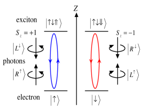
From Eq. (1), we can see that, for an incident photon with spin ( or ), if the electron is in the state , the photon will couple with the electron and be reflected by the cavity. Then the photon state is transformed into the state or , respectively, that is, both the photon’s polarization and the propagation direction are flipped. On the other hand, if the electron is in the state , there is no dipole interaction and the photon is transmitted through the cavity and acquires a mod phase shift relative to a reflected photon. Similarly, a photon with spin ( or ) will be reflected when the electron-spin state is and will be transmitted through the cavity when the electron-spin state is .
Using the above transmission and reflection rules of the photon-QD-microcavity system, we can construct a quantized obstructing object, i.e. the passing or blocking of the incident photon is controlled by an unknown quantum state rather than the experimenter. Take the right-circularly polarized photon state for example, the quantum device is shown in Fig. 1(b). The electron in a QD is initially in an arbitrary superposition state . Let a right-circularly polarized photon first passe through a polarizing beam splitter in the circular basis (c-PBS), which transmits the right circularly polarized photon and reflects the left circularly polarized photon. So the photon will enter into the cavity along the axis. According to Eq. (1), if the electron is in the state , the photon will couple with the QD, then be reflected by the cavity and become left-circularly polarized photon simultaneously. So after reflected by c-PBS, the photon will be absorbed by the detector D. While, if the electron is in the state , the photon will pass through the cavity. In short, the right-circularly polarized photon will be absorbed for electron state , and it will pass through the cavity for electron state . Therefore, the shaded area in Fig. 1(b) works as the quantum version of the obstructing object only for right-circularly polarized photons, and the blocking or passing of the photon depends on the electron’s quantum state, which is equivalent to that the obstructing object is in the superposition of presence and absence.
III The scheme of counterfactual unknown quantum state transfer
We will show the counterfactual quantum state transfer with a nested Michelson-type interferometer and QD-microcavity unit in this section. The nested Michelson-type interferometer is constructed by embedding a Michelson-type interferometer into one of the arms of another interferometer.
III.1 Partially counterfactual nonlocal entangled state generation
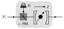
Before discussing the counterfactual quantum information transfer, it is necessary to introduce a method to generate nonlocal polarization-spin entangled state by repeatedly using a Michelson-type interferometer with a QD-microcavity inserted in one of the arms, which is used as the inner interferometer in the following quantum state transfer scheme. The setup is shown in Fig. 2, where SM indicates the switchable mirror that can be switched on and off by external means, and M is normal mirror. The two optical paths SM and SM form a Michelson-type interferometer. Optical delay (OD) is used to match the optical path lengthes of the different paths of the interferometer. The light source in Alice’s site emits left circularly polarized photons , and the excess electron in Bob’s QD is in an arbitrary state . Initially, the SM is switched off, i.e. allowing the photon to be transmitted. Once the photon enters in the interferometer, the SM is switched on (reflects the photon) and remains on during the photon travels cycles in the interferometer. So after the photon enters into the interferometer, it is firstly rotated an angle by the switchable polarization rotator (SPR), whose action is given by the transformation and . The state of the polarization-spin hybrid system becomes
| (5) |
Then the photon passes through a c-PBS. Thus, the component of the photon will be propagated to the normal mirror and stays in Alice’s site, and the component of the photon will be propagated to Bob’s site and injected into the optical microcavity to interact with the QD spin. We can see that only the right circularly polarized photon can be injected into the microcavity along the axis of the QD-microcavity, i.e. only the interactions {, } in Eq. (1) may occur in the present scheme. So in the following the superscript arrows of the photon state are omitted. After the interaction, the state of the system evolves as
| (6) |
It can be seen the component produced by interaction in Bob’s site will be reflected by c-PBS2 and absorbed by the detector D, and the component will come back to the SM in Alice’s site by optical elements. The phase shifter (PS) in Bob’s site provides a phase shift for the right circularly polarized photon state, . Therefore, when the detector does not click and the photon comes back to the SM, i.e. after the first cycle of the photon travelling in the interferometer, the state is given by
| (7) | |||||
| (8) |
Note that the above state is not normalized, because the component in Bob’s site is absorbed by the detector and the component in Eq (3) is ignored here. In the same way, after cycles, the SM is switched off to allow the photon to be transmitted and exit from the output port, and the system state becomes
| (9) |
Let , the final state is
| (10) |
which is a non-maximal polarization-spin hybrid entangled state. The probability of obtaining the entangled state is . Obviously, for the large cycles , the probability will be close to unit and the state will be normalized, , and for , the nonlocal maximal entangled state can be obtained. The present protocol may not be the optimal scheme for the nonlocal entangled state preparation, however, it is worth noting that the present scheme is partially counterfactual. During the process of the entangled-state generation, although the photon passes through the transmission channel between Alice and Bob, the photon doesn’t interact with Bob’s electron at all. From the discussions above, once the photon interacts with the electron, it will be reflected by the cavity and be absorbed by the detector. Therefore, this is an interaction-free scheme for nonlocal entangled state generation. In the following, we will show completely counterfactual entangled state generation and quantum state transfer without any particles travelling in the transmission channel.
III.2 Completely counterfactual nonlocal entangled state generation and quantum state transfer
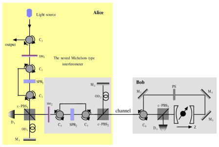
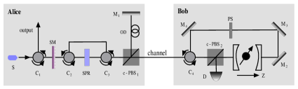
Now we show how to counterfactually generate a nonlocal entangled state and transfer an unknown quantum state from Bob to Alice without any physical particles travelling between them. The scheme is accomplished in the ideal limit, by using the nested Michelson interferometer, which is shown in Fig. 3. The interferometer in Fig. 2, as an inner interferometer, is inserted in one of the arms of an outer Michelson interferometer. The two optical paths and form the outer interferometer, which means the photon must undergo inner cycles in every outer cycle. Choosing suitable cycle numbers and corresponding to the inner interferometer and outer interferometer respectively, an unknown quantum state transfer can be counterfactually achieved with probability close to unit. Suppose sender Bob wants to transfer an arbitrary quantum state of the electron in QD to receiver Alice. Alice sends a right circularly polarized photon into the interferometer for the input port. The photon passes through the , which is switched off initially (transmits photons), and after the photon enters into the interferometer, the remains on (reflects the photon) until the photon finishes the th cycle in the outer interferometer. The performs the transformations and (), and the joint state of the photon and the electron becomes
| (11) | |||||
| (12) |
Because of the c-PBS1, the component of the state will be transmitted, while the component will be reflected and injected into the inner interferometer for going through the inner cycles. The evolution of the second term of Eq. (7) in the inner interferometer is the same as the above subsection. After the cycles in the inner interferometer, the system state is given by
| (13) |
When the photon comes back from the inner interferometer and , the component coming from the inner interferometer will be absorbed by the detector . So at the end of the first cycle in the outer interferometer, the state can be written as
| (14) |
Both Eq. (8) and Eq. (9) are not normalized, because the components absorbed by the detectors and can’t reach the SMs and be ignored. Through calculation we know when the photon finishes the th () outer cycle, the system state can be written as
| (15) |
where the parameters , , and satisfy the recursion relations
| (16) | |||
| (17) | |||
| (18) |
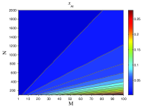
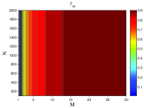
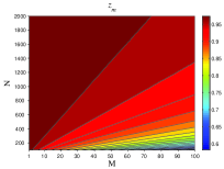
with and . When the photon finishes outer cycles, the SM1 is switched off and the photon exits from the output port. We plot the variation trend of the parameters , , and with the values of and , as shown in Fig. 4. It’s obvious that , , and for large values of and , for example, (, , and ) for ( and ), which means that after the th outer cycle, the nonlocal hybrid entangled state can be obtained with the probability close to 1. That is
| (19) |
So far, the nonlocal entangled state generation is achieved. Obviously, during the whole process, the probability that the photon travels the channel is nearly suppressed to 0 by repeatedly using the nested Michelson interferometer. In other words, as long as the photon passes through the channel, it will be absorbed by either or on the way back from Bob to Alice. So this is a counterfactual scheme with no photon passing through the transmission channel.
It’s straightway to achieve the quantum state transfer, once the entangled state in Eq. (12) is obtained. Bob performs a Hadamard transformation {,
} on the electron state, which can be implemented by using a microwave or optical pulse 22 ; 23 ; 24 , then the state is given by
| (20) |
Then Bob detects the spin in the basis {, }. If the detection result isn’t informed Alice by classical communication, Alice can obtain the teleported state with the probability of 50%, however, if the detection result is sent to Alice, she will perfectly obtain the transferred state with the help of a single-qubit phase flip gate.
It has been shown that a quantum state (or qubit) can be transferred without exchanging particle between the two participants. Compared with the typical quantum teleportation, the present scheme doesn’t require prior entanglement sharing or even classical communication. Even if Alice wants to obtain the quantum information deterministically, Bob only needs to send one bit information to Alice for the transfer of one qubit, on the contrary, two bits classical communication is required in the one-qubit teleportation procedure 2 . Moreover, while the quantum state is transferred to the photon, the initial state of the electron is destroyed by Bob’s detection, which makes the scheme avoid to violate the quantum no-cloning theorem. On the other hand, during the state transfer process, although the photon does not travel to Bob’s site, the optical path length it travels is near times that of the distance between Alice and Bob, so the scheme here cannot realize the superluminal communication. Therefore, the present scheme achieves the quantum counterfactuality without contradicting any existing physical law.
IV Analysis and discussion
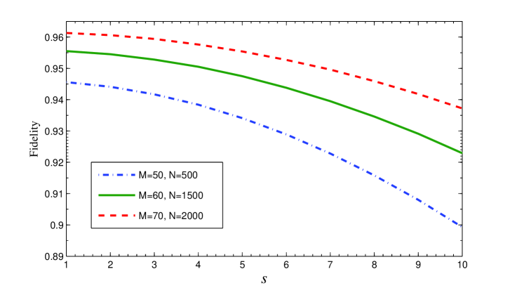
Now we analyze and discuss the performance of the quantum information transfer. Obviously, this scheme can be accomplished with the probability close to 100% under the ideal conditions. However, considering the practical experimental implementation of the present scheme, the performance must be affected by the imperfections of the system. First, the scheme requires high-precision switchable polarization rotators and to rotate a single photon state by angles and respectively, which however are bound to be introduced a slight error in the practical situations. As defined in Ref. 16 , we suppose the error coefficient of the is , which indicates the photon state is rotated with an additional angle () after each outer (inner) cycle. Therefore, we can derive the real final state after the th outer cycle by replacing the rotated angles () in the recursion relations of Eq. (11) with (). In order to estimate the influence of the SPRs error, we analyze the average fidelity of the system state after outer cycles. Without loss of generality, let the normalization coefficients and in Eq. (12) equal and , respectively. And the average fidelity of the final state can be written as . Assume the error coefficients , we numerically estimate the average fidelity and plot its change with for different values of and in Fig. 5, which indicates that the fidelity is higher for lesser error factor .
Other crucial influence factors come from the spin-cavity system that is the key component in the present scheme. It seems that the performance of the spin-cavity unit does not affect the counterfactual quantum state transfer scheme since no photon passes through transmission channel to interact with the quantum dot during the whole process. However, the spin-cavity system can affect the scheme through influencing the efficiency of the inner interferometer. Therefore, we can estimate the effect coming from the performance of the spin-cavity system by analyzing the successful probability of the partially counterfactual entangled state generation in Sec. III(A). The reflection and transmission coefficients of coupled and the uncoupled cavities are generally different when the side leakage and the cavity loss are not negligible, which has been illustrated in the Ref. 21 . Under the assumption of weak excitation limit, the reflection and transmission coefficients of a double-sided optical microcavity are described by 19 ; 21
| (21) | |||
| (22) | |||
| (23) |
where is the coupling strength between and the cavity field; , , and are respectively the frequencies of the input photon, the cavity field, and the transition; , , and are the cavity field decay rate, the side leakage rate, and the dipole decay rate, respectively. For the case that the QD does not interact with the input photon, i.e. , under the resonant interaction condition , the reflection and transmission coefficients become
| (24) | |||
| (25) | |||
| (26) |
Therefore, considering the side leakage and the cavity loss, the rules of optical transitions in a realistic -cavity system used in this paper become 19 ; 20 ; 21
| (27) | |||
| (28) |
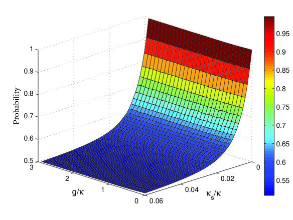
Using above transition rules, we can calculate the probability of generating the entangled state in Eq. (6) under the presence of side leakage and cavity loss. In order to illuminate the effect of the spin-cavity system, we plot the probability of entangled state generation versus the side leakage rate and the normalized coupling strength by means of numerical simulation in the case of and , as shown in Fig. 6, which indicates that the present scheme is especially sensitive to the side leakage rate but the effect of the coupling strength is negligible. The numerical result is not difficult to understand by reviewing the partially counterfactual entangled state generation process, in which the photon passes through cycles (here ) in the inner interferometer but does not interact with the electron in the QD. It is clear that the scheme requires optical cavity with extremely high quality factor, for example, the probability only equals 0.63 for and , which is a strong challenge for side leakage in experiments 25 . Fortunately, the improvement of fabrication techniques can suppress the side leakage 26 . When the side leakage can be neglected compared with the main cavity decay, i.e. , the probability will approach unity.
In addition, the electron spin qubit used in the present scheme and its fast initialization have been demonstrated 27 , and the photon qubit can be produced with the well-known spontaneous parametric down-conversion 28 ; 29 . However, the background noise will be produced during the process of photons’ generation, transmission, and detection, which is larger than the single photon signal. In order to accomplish the scheme successfully, the experiment should be performed under the condition with high signal-noise ratio. Some recent works 30 ; 31 have demonstrated the unwanted background photons can be efficiently reduced in the parametric down-conversion process by using the optical shutter controlled by a simple field programable gate array. The background noise can also be suppressed by optimizing the detuning between the frequencies of the pump and photon pairs and cooling the nonlinear fiber 31 . We also note that the two detectors in our scheme are only used to absorb the photon passed through the transmission channel, therefore, if the scheme is completed successfully, it means the detectors detected no photon in the whole process. In this sense, the sensitivity and dark counts of the detectors do not influence the efficiency of the scheme, and the detectors can even be replaced with other absorption objects.
From the discussion and analysis above, the present scheme is implementable in principle, but there may be some challenges for current experiment conditions in practice. Nevertheless, compared with the experimental difficulties and the practical applications of the present scheme, perhaps the mind-boggling and highly counter-intuitive fact of transferring quantum information without transferring any particles is more worthy to pay attention, and the deeper physical mechanism behind the counterfactual protocol may be more interesting. Very recently, Vaidman et al. 32 reported a series of interesting works about the past of photons passing through a nested Mach-Zehnder interferometer. Based on the locality of physical interactions, they proposed a method to analyze the past of a photon via the weak trace it leaves, which can be explained in the two-state vector formulation (TSVF) of quantum mechanics 33 . The results showed that the past of photons can’t be represented by continuous trajectories and should be described by both forward- and backward-evolving quantum states. That means a photon may be in every place between its emission and detection points. These works maybe provide a line of thinking for explaining the counterfactuality of the present scheme, i.e. considering photons as delocalized waves with discontinuous trajectories in the interferometer, i.e. considering photons as delocalized waves with discontinuous trajectories in the interferometer. On the other hand, perhaps the present counterfactual scheme can also provide evidence for the viewpoint in Ref. 32 . This issue is interesting, and is worth studying further in the future.
V Conclusions
In conclusion, we have proposed a counterfactual scheme for transferring an unknown quantum state. The scheme indicated that a qubit can be teleported to a distant place without any physical particles travelling between them. The present scheme does not require prior entanglement sharing and classical communication between the two distant participants, so it essentially differs from the typical teleportation. In addition, it is necessary to entangle two nonlocal qubits without interaction during the process of the quantum state transfer, thus the scheme can also be used to generate nonlocal entanglement counterfactually. We also numerically estimated the effect of the imperfections of the experiment system, which indicated our scheme required optical microcavity with high quality factor.
This work is supported by the National Natural Science Foundation of China under Grant Nos. 61068001 and 11264042; China Postdoctoral Science Foundation under Grant No. 2012M520612; the Program for Chun Miao Excellent Talents of Jilin Provincial Department of Education under Grant No. 201316; and the Talent Program of Yanbian University of China under Grant No. 950010001.
References
- (1) M. A. Nielsen and I. L. Chuang, Quantum computation and quantum information (Cambridge university press, Cambridge, U.K., 2000).
- (2) C. H. Bennett, G. Brassard, C. Crépeau, R. Jozsa, A. Peres, and W. K. Wootters, Phys. Rev. Lett. 70, 1895 (1993).
- (3) D. Bouwmeester, J. W. Pan, K. Mattle, M. Eibl, H. Weinfurter, and A. Zeilinger, Nature (London) 390, 575 (1997).
- (4) A. Furusawa, J. L. Sørensen, S. L. Braunstein, C. A. Fuchs, H. J. Kimble, and E. S. Polzik, Science 282, 706 (1998).
- (5) M. A. Nielsen, E. Knill, and R. Laflamme, Nature (London) 396, 52 (1998).
- (6) J. I.Cirac, P. Zoller, H. J. Kimble, and H. Mabuchi, Phys. Rev. Lett. 78, 3221 (1997).
- (7) D. N. Matsukevich and A. Kuzmich, Science 306 663 (2004).
- (8) M. A. Sillanpää, J. I. Park, and R. W. Simmonds, Nature (London) 449, 438 (2007).
- (9) A. C. Elitzur and L. Vaidman, Found. Phys. 23, 987 (1993).
- (10) P. Kwiat, H. Weinfurter, T. Herzog, A. Zeilinger, and M. A. Kasevich, Phys. Rev. Lett. 74, 4763 (1995).
- (11) B. Misra and E. C. G. Sudarshan, J. Math. Phys. 18, 756 (1977).
- (12) O. Hosten, M. T. Rakher, J. T. Barreiro, N. A. Peters, and P. G. Kwiat, Nature (London) 439, 949 (2006).
- (13) T.-G. Noh, Phys. Rev. Lett. 103, 230501 (2009).
- (14) Z. Q. Yin, H. W. Li, W. Chen, Z. F. Han, and G. C. Guo, Phy. Rev. A 82, 042335 (2010); Z. Q. Yin, H. W. Li, Y. Yao, C. M. Zhang, S. Wang, W. Chen, G. C. Guo, and Z. F. Han, ibid. 86, 022313 (2012).
- (15) Y. Liu, L. Ju, X. L. Liang, S. B. Tang, G. L. Shen Tu, L. Zhou, C. Z. Peng, K. Chen, T. Y. Chen, Z. B. Chen, and J. W. Pan, Phys. Rev. Lett. 109, 030501 (2012); G. Brida, A. Cavanna, I.P. Degiovanni, M. Genovese, and P.Traina, Laser Phys. Lett. 9, 247 (2012).
- (16) H. Salih, Z. H. Li, M. Al-Amri, and M. S. Zubairy, Phys. Rev. Lett. 110, 170502 (2013).
- (17) N. Gisin, Phys. Rev. A 88, 030301 (2013).
- (18) J. L. Zhang, F. Z. Guo, F. Gao, B. Liu, and Q. Y. Wen, Phys. Rev. A 88, 022334 (2013).
- (19) C. Y. Hu, W. J. Munro, J. L. O’Brien, and J. G. Rarity, Phys. Rev. B 80, 205326 (2009).
- (20) C. Bonato, F. Haupt, S. S. R. Oemrawsingh, J. Gudat, D. Ding, M. P. van Exter, and D. Bouwmeester, Phys. Rev. Lett. 104, 160503 (2010).
- (21) C. Y. Hu and J. G. Rarity, Phys. Rev. B 83, 115303 (2011).
- (22) D. Press, T. D. Ladd, B. Y. Zhang, and Y. Yamamoto, Nature (London) 456, 218 (2008).
- (23) J. Berezovsky, M. H. Mikkelsen, N. G. Stoltz, L. A. Coldren, and D. D. Awschalom, Science 320, 349 (2008).
- (24) A. Greilich, S. E. Economou, S. Spatzek, D. R. Yakovlev, D. Reuter, A. D. Wieck, T. L. Reinecke and M. Bayer, Nature Phys. 5, 262 (2009).
- (25) J. P. Reithmaier, G. Sek, A. L offler, C. Hofmann, S. Kuhn, S. Reitzenstein, L. V. Keldysh, V. D. Kulakovskii, T. L. Reinecke, and A. Forchel, Nature (London) 432, 197(2004).
- (26) S. Reitzenstein, C. Hofmann, A. Gorbunov, M. Strauß, S. H. Kwon, C. Schneider, A. Löffler, S. Höfling, M. Kamp, and A. Forchel, Appl. Phys. Lett. 90, 251109 (2007).
- (27) C. Emary, X. Xu, D. G. Steel, S. Saikin, and L. J. Sham, Phys. Rev. Lett. 98, 047401 (2007); D. Kim, S. E. Economou, S. C. Badescu, M. Scheibner, A. S. Bracker,M. Bashkansky, T. L. Reinecke, and D. Gammon, ibid. 101, 236804 (2008); D. Press, T. D. Ladd, B. Zhang, and Y. Yamamoto, Nature (London) 456, 218 (2008).
- (28) J.-W. Pan, Z.-B. Chen, C.-Y. Lu, H. Weinfurter, A. Zeilinger, and M. Żukowski, Rev. Mod. Phys. 84, 777 (2012).
- (29) P. G. Kwiat, K. Mattle, H. Weinfurter, A. Zeilinger, A. V. Sergienko, and Y. Shih, Phys. Rev. Lett. 75, 4337 (1995).
- (30) G. Brida, I. P. Degiovanni, M. Genovese, A. Migdall, F. Piacentini, S. V. Polyakov, and I. R. Berchera, Opt. Express 19, 1484 (2011).
- (31) L. Yang, F. Sun, N. Zhao, and X. Li, Opt. Express 22, 2553 (2014).
- (32) L. Vaidman, Phys. Rev. A 87, 052104 (2013); A. Danan, D. Farfurnik, S. Bar-Ad, and L. Vaidman, Phys. Rev. Lett. 111, 240402 (2013); L. Vaidman, Phys. Rev. A 89, 024102 (2014).
- (33) Y. Aharonov, P. G. Bergmann, and J. L. Lebowitz, Phys. Rev. 134, B1410 (1964); Y. Aharonov and L. Vaidman, Phys. Rev. A 41, 11 (1990).