Low-distance Surface Codes under Realistic Quantum Noise
Abstract
We study the performance of distance-three surface code layouts under realistic multi-parameter noise models. We first calculate their thresholds under depolarizing noise. We then compare a Pauli-twirl approximation of amplitude and phase damping to amplitude and phase damping. We find the approximate channel results in a pessimistic estimate of the logical error rate, indicating the realistic threshold may be higher than previously estimated. From Monte-Carlo simulations, we identify experimental parameters for which these layouts admit reliable computation. Due to its low resource cost and superior performance, we conclude that the 17-qubit layout should be targeted in early experimental implementations of the surface code. We find that architectures with gate times in the 5–40 ns range and times of at least 1–2 s will exhibit improved logical error rates with a 17-qubit surface code encoding.
I Introduction
Topological quantum error-correcting codes are a leading approach to scalable fault-tolerant quantum computation Fowler et al. (2012a); Lidar and Brun (2013). The most practical topological code to date is the surface code, which calls for a 2-D planar qubit layout with only nearest-neighbor interactions Bravyi and Kitaev (1998); Kitaev (2003); Raussendorf and Harrington (2007); Fowler et al. (2009). It has been shown to allow error rates up to a threshold of approximately 1% Fowler et al. (2012b, a); Wang et al. (2011); Stephens (2013). Several quantum architectures, including superconducting devices Helmer et al. (2009); DiVincenzo (2009) and ion traps Kielpinski et al. (2002); Monroe et al. (2014); Merrill et al. (2011); Wright et al. (2013), are suitable for realizing the surface code. Recent experiments on superconducting qubits have even demonstrated error rates in the required range Barends et al. (2014).
Until recently, the threshold for the surface code has been primarily calculated for the depolarizing channel Fowler et al. (2012b, a); Wang et al. (2011); Stephens (2013). Simulation of the surface code and the depolarizing channel requires only Clifford operations and Pauli measurements on stabilizer states, allowing efficient simulation on a classical computer under the Gottesman-Knill theorem Gottesman (1999); Aaronson and Gottesman (2004).
It has been shown that realistic quantum noise such as decoherence can be sufficiently approximated by a depolarizing noise model parametrized by a method such as Pauli twirling Silva et al. (2008); Nielsen and Chuang (2000), enabling efficient simulation. Simulations of the surface code with noise based on Pauli-twirl approximations have been performed for several superconductor architectures Ghosh et al. (2012). Other studies have achieved efficient classical simulation of realistic noise models by using Clifford gates to approximate arbitrary gates Magesan et al. (2013); Puzzuoli et al. (2014) and amplitude damping Gutiérrez et al. (2013).
More recently, it has been shown that the surface code threshold is significantly degraded in the presence of qubit leakage in conjunction with depolarizing noise Fowler (2013a). It has also been shown to achieve arbitrary reliability given modest additional qubit resources under local many-qubit errors and non-local two-qubit errors Fowler and Martinis (2014). A recent study has determined a threshold for the surface code considering correlated errors and the coupling between qubits and the environment by formulating the problem as an Ising model Jouzdani et al. (2014).
In all cases, the thresholds have been calculated for a standard surface code layout. Variations of the surface code layout have been proposed Bombin and Martin-Delgado (2007); Horsman et al. (2012) that reduce the qubit and gate resources necessary for implementation. To the best of our knowledge, the thresholds for these modified surface code layouts have not been analyzed. In addition, studies of the threshold under realistic (non-Clifford) noise models have been limited due to the exponential cost of simulation. With device error rates rapidly approaching the surface code threshold, it is timely to investigate the performance and requirements of low-distance surface code layouts for near-term experimental implementation.
In this work, we determine the threshold for distance-three surface code layouts under depolarizing and realistic noise models. We study the layouts under an amplitude and phase damping channel and an approximation of the channel using Pauli twirling Ghosh et al. (2012). Our studies demand simulation of non-Clifford operations, which requires memory exponential in the number of qubits. We use the LIQ Wecker and Svore (2014) software architecture for our simulations. We also outline parameter regimes that enable reliable quantum error correction for low-distance surface codes and present a decoder based on a small lookup table optimized for distance-three layouts and limited classical computation.
Our paper is organized as follows. Section II briefly reviews the surface code and three layouts for the distance-three code. We introduce our decoding method, based on a small lookup table, in Section III. Section IV describes the realistic noise models and their approximations. Our experimental methodology is introduced in Section V. In Section VI, we present our surface code simulation results. Finally, we conclude in Section VII.
II Low-distance Surface codes
The surface code is a stabilizer code arranged on a 2-D lattice with nearest-neighbor interactions Bravyi and Kitaev (1998). It encodes a single logical qubit in a number of physical qubits that is determined by the code distance and desired layout (described below). Through repeated measurement of its stabilizer generators, the surface code in conjunction with a classical decoding algorithm can detect errors and subsequently correct up to physical errors. The distance dictates the length of the shortest undetectable error chain and in turn is also the length of the shortest logical operator. For an excellent review of the surface code, we refer the reader to Fowler et al. (2012a).
II.1 25-qubit Layout
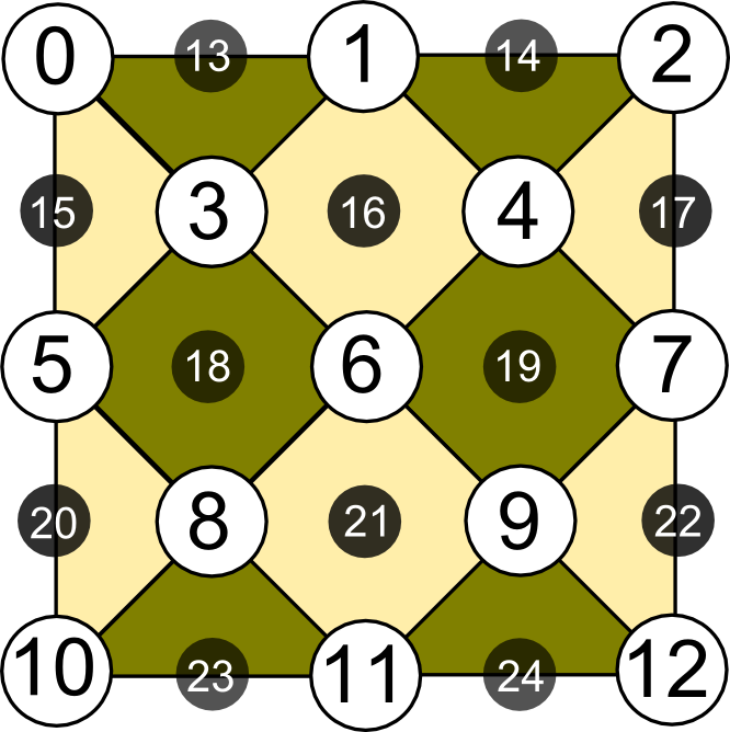
We study three different distance layouts, shown in Figure 1. We begin by discussing the standard layout, referred to as Surface-25, shown in Figure 1(a). It uses a square grid of qubits with a smooth and rough boundary Kitaev (2003). For , the grid contains qubits of which data qubits (large white circles) are used to encode the logical qubit and syndrome qubits (small black circles) are used to extract the error syndromes by way of stabilizer measurements.
 |
 |
 |
| (a) Surface-25 | (b) Surface-17 | (c) Surface-13 |
Surface-25 is simultaneously stabilized by the group of stabilizer generators listed in Table 2. In Fig. 1, the stabilizers are represented by light (yellow) patches and the stabilizers are represented by dark (green) patches, where each patch represents a tensor product of (or ) operators on the data qubits surrounding the patch.
A logical operator is defined as a chain of physical operations between two data qubits on opposite smooth boundaries (top and bottom edges). The chain is allowed to cross any stabilizer patch and follow any edge of an stabilizer patch. A logical operator is defined analogously as a chain of physical operations between two data qubits on opposite rough boundaries (left and right edges). Table 2 lists one possible logical and operator. There are equivalent logical operators for each logical Pauli operator ( and ), where is the number of stabilizer generators for the given surface code. Since and commute with all of the stabilizers and cannot be written as a product of them, logical errors, which come in the form of logical operators, cannot be detected by the code.
The surface code detects errors through the eigenvalues of the stabilizers. A bit-flip (phase-flip) on a data qubit will change the eigenvalue of adjacent () stabilizers. To extract an eigenvalue, also referred to as an error syndrome, a given stabilizer is measured. Figure 2 shows the standard quantum circuit for measuring the stabilizers Fowler et al. (2012a); Stephens (2013), where data qubit corresponds to the top (north) qubit and corresponds to the bottom (south) qubit of each diamond patch in Fig. 1(a).
The circuit begins with CNOT gates that propagate error information from the data qubits ,,, to the syndrome qubit (black circle). CNOT gates are performed in the order: top (); left (); right (); bottom (). Cyclic orders, such as a clockwise or counter-clockwise, i.e., , fail to maintain commutation of nearby stabilizers, which in turn can cause random measurement outcomes Fowler et al. (2012a). Thus the order of CNOT gates is required to follow an “S” or “Z” shape.
The syndrome qubit is then measured to extract the eigenvalue of the stabilizer. These error syndromes are input to a classical decoding algorithm to determine an appropriate correction operator. Details of our decoding algorithm are given in Section III. The total number of operations in a given round of stabilizer measurements for the surface code is given in Table 1.

(a)

(b)
| Code | CNOT | Meas. | Prep. | Depth | ||
|---|---|---|---|---|---|---|
| Surface-13 | ||||||
| Surface-17 | ||||||
| Surface-25 |
| Surface-25 | Surface-13, Surface-17 | ||
| Stabilizers | Stabilizers | Stabilizers | Stabilizers |
| Logical | Logical | Logical | Logical |
II.2 13- and 17-qubit Layouts
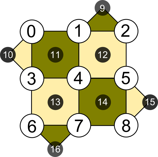
The number of qubits in Surface-25 can be reduced while maintaining the same code distance by rotating it clockwise by degrees and removing the four corner data qubits Bombin and Martin-Delgado (2007); Horsman et al. (2012), shown in Fig. 1(b). The number of data qubits is reduced from to and the number of syndrome qubits is reduced to for a total of qubits. We call this layout Surface-17. The stabilizer generators contain weight-4 and weight-2 stabilizers (Table 2). Figure 3(a) shows the circuit for a simultaneous weight-4 and weight-2 stabilizer measurement.

(a)

(b)
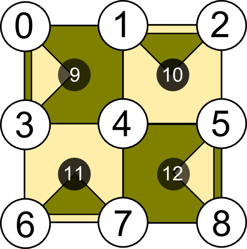
A further reduction in qubits can be obtained by reusing the syndrome qubits Horsman et al. (2012). Surface-13 uses only syndrome qubits as shown in Fig. 1(c). Each syndrome qubit is used twice, once for stabilizer measurement and once for stabilizer measurement. Figure 3(b) contains the corresponding circuit for measuring a weight-4 stabilizer followed by a weight-2 stabilizer. Surface-13 reduces the number of qubits but increases the depth of a round by 4 time steps. The depth and number of operations required for one round of the surface code for Surface-17 and 13 are given in Table 1. The stabilizers and logical operations for these two layouts are listed in Table 2.
Despite having fewer stabilizers, Surface-17 and Surface-13 still remain distance-three surface codes Bombin and Martin-Delgado (2007); Horsman et al. (2012). Due to their reduction in resources by 32–48%, these layouts are promising candidates for early experimental implementation. In Section VI, we determine which layout is most promising based on its threshold and resource costs.
III Decoding Method
A standard method for mapping error syndromes to the most probable error chain is the minimum weight perfect matching algorithm Fowler et al. (2012b); Edmonds (1965a, b). It requires time for detection events if executed serially, and time if executed in parallel Fowler (2013b). The algorithm independently corrects and errors by identifying the most likely error chain for each type such that the total chain weight is minimal. The algorithm has recently been extended to handle correlations between and errors, in which case the chains are not constructed independently Fowler (2013c). Corrections are applied along the chain(s). If after correction a chain of errors connecting two smooth (rough) boundaries remains, then a logical error has occurred. If errors are assumed to be independent, then long chains will be exponentially unlikely.
III.1 Lookup Table Decoder
In this work we target first-generation implementations of a single qubit protected by a small surface code. While the classical time and space requirements of the minimum weight perfect matching algorithm are modest, we further reduce the classical computational overhead by designing a lookup table based on the algorithm that can be implemented on a small classical device. Our lookup table is designed to find the most probable low-weight error chain from a short history of error syndromes.
Consider the set of error syndromes that indicate an error after one full (noisy) round of the surface code, that is, those indicating a eigenvalue. Based on the error syndrome locations, the decoder determines the probable data-qubit error locations. For example, consider a error on qubit in Surface-17 (Fig. 1(b)). Given that no other errors occur, after one round of the surface code syndrome qubits and will indicate an error. The decoder will determine the shortest error chain connecting these two syndromes includes data qubit . To correct the error chain, will be applied.
As another example, consider an error on qubit . It will cause syndrome to indicate an error. Since syndromes and do not indicate errors, the decoder will infer an error on either data qubit or . In this case, the decoder can correct either or since is a stabilizer.
An error syndrome may also occur due to a measurement error. However, the decoder may interpret it as a data-qubit error. For example, consider a measurement error on qubit . The decoder will either apply or to “correct” the error, thereby adding an error to a clean data qubit.
To improve identification of actual data-qubit errors, inference is performed based on several rounds of stabilizer measurements Fowler et al. (2012b). Consider performing rounds of the surface code consecutively. Instead of storing the syndromes for each round, we store the locations in time and space of the syndromes whose values change, or “flip”, between the current and previous round.
For rounds, this requires storing a 3-D space-time array containing at most values, where is the maximum number of syndrome changes in a round. We refer to this 3-D array as the syndrome volume, where dimension represents time. The goal is to determine a correction operator (a product of and/or operators) based on the syndrome volume such that the number of errors remaining after correction is minimized, in turn reducing the chance of forming a logical error chain.
Our lookup table is based on the fact that short error chains are more likely than long chains. Assuming a syndrome volume contains rounds, we construct a lookup table based on the following rules (Figure 4 shows the rules visually):
-
1.
If the same syndrome flips twice in two consecutive rounds, the pair (in time) of syndromes is ignored since it most likely indicates a measurement error.
-
2.
If a pair (in space) of neighboring syndromes flips in the same round, a correction on the data qubit between the pair is applied.
-
3.
If a syndrome flips in round and its neighboring syndrome flips in round , a correction on the data qubit between the pair (in time) is applied.
-
4.
If a syndrome flips only once and in a round other than the last, a correction is applied to a data qubit on the boundary such that the data qubit is not between two stabilizers that did not indicate a syndrome.
-
5.
If a single syndrome flips only once and in the last round, the information is kept until the next round of error correction. No correction based on this syndrome is applied. In this case the location of the error, if any, is inconclusive without another round of syndrome measurements.

We decode by checking the above rules in order and determining the set of data-qubit error locations. We then switch the order of rules 2 and 3 and determine another set of possible error locations. We correct based on the set with fewer error locations, since fewer errors are more likely. Here we assume that .
These rules are equivalent to the minimum weight perfect matching algorithm applied to only neighboring-syndrome pairs, with uniform weight for the same distance. Since our surface codes are small, performance of the code does not improve when decoding considers more distant pairs.
We encode these rules into a lookup table. The lookup table maps the syndrome volume of measurement flips to a set of probable errors on the data qubits. The table requires constant time and space, where is the number of data qubits.
III.2 Improved Stabilizer Measurement Circuits
In our simulations of Surface-13 and 17 under noise, we find that using the same CNOT ordering for both - and -type stabilizer measurements could result in a single error on a syndrome qubit, leading to a logical or error (details on noise are given in Sec. IV). Figure 5(a) shows an example. A error on a -stabilizer syndrome qubit after the first two CNOT gates propagates onto two horizontally aligned data qubits. Since our surface codes require only three data qubits to complete a logical error chain, the next round of syndrome measurements will incorrectly diagnose a error on the third qubit, leading to a logical error chain.

(a)

(b)
To prevent the creation of a logical error, we propose to measure - and -type stabilizers in different orders. The sequence for stabilizers is the same as in Figure 2. We modify the order of CNOTs in stabilizers as: top right (); bottom right (); top left (); bottom left () (Figure 5(b)). This order maintains the alignment of qubits and such that they are perpendicular to the direction of the corresponding logical chain. It also preserves the commutation relations as well as the circuit depth and size. Fig. 5 shows an example where two errors map to a single error with the new order, versus a logical error with the old order. We use this new order for all simulations in this paper.
IV Noise models
In this section, we present the noise models considered in our surface code simulations. We review two noise models that can be simulated efficiently on a classical computer (depolarizing and Pauli-twirl approximation) and one noise model that requires exponential memory to simulate (amplitude and phase damping).
IV.1 Symmetric and Asymmetric Depolarizing Channels
The depolarizing channel () is a standard quantum noise model in which a qubit becomes depolarized with a given probability . This channel transforms a density matrix of a single qubit as
| (1) |
where . In this model, a qubit suffers from discrete Pauli bit-flip (), phase-flip (), or bit-and-phase flip () errors with probabilities , , and , respectively. When , this channel is called a symmetric depolarizing channel. When the probabilities are independent, the model is called an asymmetric depolarizing channel.
IV.2 Amplitude and Phase Damping Channel
The amplitude damping channel () characterizes the behavior of energy dissipation of the quantum system, including spontaneous emission of a photon from a qubit. This channel transforms the density matrix of a single qubit as
| (2) |
where
| (3) |
and is the probability of a qubit emitting a single photon.
Figure 6 expresses amplitude damping of a single qubit in the form of a quantum circuit where an ancilla qubit is used to represent the environment and Nielsen and Chuang (2000). The input is an arbitrary single-qubit state and the output state is given by
where is a normalization constant. The probabilities of measuring 0 and 1 are and , respectively.
During simulation, we do not use an extra ancilla as shown in the circuit in Figure 6. Instead, we calculate the probability of measuring and given input state , and simulate the measurement outcome with a random number. When the simulated measurement is , we apply the rotation on . When it is , we apply damping and the state becomes .
The phase damping channel () is described similarly as
| (4) |
where
| (5) |
Phase damping noise, also called pure dephasing, is equivalent to the phase-flip channel. By unitary freedom of operator-sum representation, we can derive a new set of operation elements to express the channel in terms of the probability of a phase-flip () error,
| (6) |
where .
We assume that amplitude and phase damping () are the main sources of decoherence. Using these two channels together, decoherence on a single qubit transforms the density matrix as
| (7) |
where is the execution time of the gate including identity, and are the single-qubit relaxation and dephasing times, respectively, and and Nielsen and Chuang (2000).
IV.3 Approximate Amplitude and Phase Damping Channel
Using a technique called Pauli twirling () Silva et al. (2008), a Pauli channel can be used to approximate the decoherence channel given in Eq 7 Ghosh et al. (2012); Sarvepalli et al. (2009), where
| (8) |
Twirling results in removal of the off-diagonal terms and in turn allows expression of the channel as an asymmetric depolarizing noise channel (given in Eq 1) with the probabilities given by
| (9) | |||
| (10) |
where the probabilities of failure are expressed in terms of the execution time of a gate, the qubit relaxation time , and the qubit dephasing time Ghosh et al. (2012).
Assuming errors are independent, the probabilities of two-qubit errors, for example when a CNOT gate fails, are approximated as in Ghosh et al. (2012) as
V Experimental Setup
We use the LIQ software architecture Wecker and Svore (2014) to perform simulations of the surface code under noise. LIQ (Language-integrated Quantum Operations) contains an embedded, domain-specific language for programming quantum circuits as well as two circuit simulation environments. The first environment allows efficient simulation of Clifford circuits, based on the Gottesman-Knill theorem, and is called Stabilizer simulation Gottesman (1999); Aaronson and Gottesman (2004). The second environment, called Universal simulation, allows full simulation of arbitrary quantum circuits.
While some of our noise models allow Stabilizer simulation, we have chosen for consistency to perform all simulations within the Universal simulation environment. LIQ allows universal simulation of a number of qubits that is limited by the main memory of the machine. We ran simulations on a large HPC cluster containing several hundred nodes with 32GB of RAM each, allowing simulation of up to roughly 30 qubits on each node. Our simulations required thousands of hours of compute time.
V.1 Monte-Carlo Simulation

We restrict the operations in our circuits to the five types given in Table 1, which we refer to as location types: , , CNOT, Prepare a state, and Measure in the basis. When no location type is specified on a qubit, the identity gate is applied to that qubit, where the duration of the identity is set by the location type occurring on other qubits in the time step. When a qubit is idle for a duration of time steps (while gates are being applied on other qubits), we apply identity gates to it to simplify the simulations. Figure 7 shows the circuit of Figure 3(a) with identity gates inserted. Further circuit optimization can be performed, for example by delaying qubit preparation and measuring a qubit as soon as gate operations complete. Such optimization will result in improved thresholds. For simplicity, we choose to maintain gate alignment between stabilizers.
We perform Monte-Carlo simulation of the surface code layouts to compute the logical error rates. At each time step of the circuit, each qubit undergoes a location type followed by the given noise model. For depolarizing noise and approximate damping noise, we replace each location type except measurement by the location type followed by an , , or gate (“error”) with probability , , and , respectively. In the case of measurements, , , or errors are placed before the measurement location.
V.2 Logical Error Rate Calculation

We calculate the logical error rate of a given layout by simulating it under the various noise models. At the start of each simulation, we initialize all data qubits to (if preparing ) or (if preparing ) and run a noise-free cycle of syndrome measurements to project into an initial stabilizer state of the code. We refer to this state as the quiescent state Fowler et al. (2012a). Note that for a code with stabilizers, there are possible quiescent states, since each stabilizer measurement can randomly project to either a eigenstate. In the absence of noise, the quiescent state will be maintained during subsequent rounds of the surface code.
After initialization of the quiescent state, the simulation proceeds as follows:
-
1.
Execute two rounds of the surface code with noise (execute three if this is the first execution of the loop). Record the list of syndrome flips between contiguous rounds in the syndrome volume. For the first round, compare to the quiescent state.
-
2.
Apply the decoder (Section III) to the three-layer syndrome volume to determine the most probable set of error locations.
-
3.
Apply noise-free corrections to the state. In practice, corrections can be tracked directly in software.
-
4.
Check for a logical error by calculating the distance of the state to the possible logical states. If the closest logical state is incorrect, count a logical error.
-
5.
Repeat from Step 1 until logical errors are detected.
After each logical error check (Step 4) the syndrome volume contains a list of unpaired syndrome flips due to the last two rules of our decoder. Each syndrome volume, as shown in Fig. 8, thus contains three layers: the final layer from the previous volume and two layers from two additional rounds of the surface code. We refer to the number of rounds in the volume as the window size. We experimented with various window sizes and found three was optimal for distance-three layouts. In our simulations, varies between 10 and 200 depending on the size of the physical error rates.
We calculate the logical error rate per window since in an experiment, the logical qubit will be measured after completion of a window to ensure optimal decoding and correction. For a window containing rounds, the logical error rate is given by
| (11) |
where represents the number of windows executed to observe logical errors. When , Eq 11 represents the logical error rate per round of the surface code.
Since we only calculate for distance , we estimate the pseudothreshold Svore et al. (2006, 2005), denoted as as opposed to the asymptotic threshold as . The pseudothreshold can be defined by the crossing point between the line and the plot vs. . If the error rate of each physical location type falls below the pseudothreshold , then the code is guaranteed to lower the logical error rate below .
The logical error rate per window and the logical error rate per round are related by
| (12) |
For depolarizing noise, we calculate (to compare with previous work) and . For amplitude and phase damping and the Pauli-twirl approximation, we calculate .
V.3 Architectural Settings
| Parameter | Description/Location | (Slow) | (Fast) | (DiVincenzo) | (Helmer) | (Slow) | (Fast) |
|---|---|---|---|---|---|---|---|
| qubit relaxation time | |||||||
| qubit dephasing time | |||||||
| state preparation | 5 s | 1 s | 40 ns | 40 ns | 100 s | 30 s | |
| single-qubit rotation | 100 ns | 10 ns | 5 ns | 5 ns | 1 s | 1 s | |
| measurement | 5 s | 1 s | 35 ns | 35 ns | 100 s | 30 s | |
| CNOT | 1 s | 100 ns | 80 ns | 20 ns | 100 s | 10 s | |
| one round (S-13) | 28.2 s | 4.82 s | 800 ns | 320 ns | 1202 s | 202 s | |
| one round (S-17, S-25) | 14.2 s | 2.42 s | 405 ns | 165 ns | 602 s | 102 s |
For amplitude and phase damping and the Pauli-twirl approximation, we consider several parameter settings derived from superconductor and ion trap architectures. These architectures are well-suited to 2-D, nearest-neighbor operations required for the surface code. Table 3 lists the different parameter settings considered for each architecture. The time per round indicates the time required to complete one round of the surface code given the other parameters. These six architecture settings represent a range of round times between ns to ns for Surface-17 and Surface-25. Note that the Surface-13 layout requires roughly twice the amount of time of Surface-17.
2D superconducting architectures have demonstrated fast single- and two-qubit gate execution times in recent years DiCarlo et al. (2010); Chow et al. (2010, 2013); Barends et al. (2014). Current gate times are in the range of – ns and – ns for single-qubit and two-qubit gates, respectively, with experimental times as long as – s Chow et al. (2013); Barends et al. (2014). The DiVincenzo () DiVincenzo (2009) and Helmer () Helmer et al. (2009) superconductor parameters are derived from Ghosh et al. (2012). requires longer CNOT gate times than . and represent parameters for slow and fast gate times, respectively, based on recent experiments DiCarlo et al. (2010); Chow et al. (2010). In particular, they account for s preparation and measurement times, while and assume ns times.
Ion traps are another promising architecture with demonstrable quantum gates Kielpinski et al. (2002); Monroe et al. (2014); Merrill et al. (2011); Wright et al. (2013); Harty et al. (2014). While trapped ion devices tend to have longer gate execution times than superconductor devices, they have been shown to have much longer relaxation and dephasing times in the range of 780–1800 ms Häffner et al. (2008); Noek et al. (2013). Recently, a time of 50 s has been reported Harty et al. (2014). accounts for gate times observed in current experiments and longer preparation and measurement times Noek et al. (2013); Häffner et al. (2008); Brown (2013). accounts for gate, preparation, and measurement times of a proposed scalable ion trap quantum computer model Monroe et al. (2014). It assumes that all gate operations are within one Elementary Logic Unit (ELU) with 10–100 qubits arranged linearly. ELUs are connected to each other using photonic quantum channels to achieve modular scalability.
VI Experimental Results
In this section we analyze numerical Monte-Carlo simulations of the distance-three surface code layouts under the multi-parameter noise models. We first determine the distance-three layout that admits the highest pseudothreshold under depolarizing noise. We then study the performance of the preferred layout under several realistic noise models. In particular, for the six architectural settings we compare the accuracy of the approximate amplitude and phase damping channel, which can be efficiently simulated, to the amplitude and phase damping channel, which requires universal simulation. In each plot, error bars indicate the upper bound statistical significance using the standard deviation.
VI.1 Depolarizing Noise
We begin by calculating the symmetric depolarizing noise threshold for each distance-three layout. In this model, each location fails with probability . For single-qubit locations, and . For two-qubit locations, and . Since the circuits and round times differ, we expect the pseudothreshold to vary for each layout.
 |
| (a) Surface-13 |
 |
| (b) Surface-17 |
 |
| (c) Surface-25 |
Figure 9 plots the location error rate versus the logical error rate per round for Surface-13, 17, and 25, where each layout encodes a logical state and we check for a logical bit-flip . Each point represents between and independent simulation runs.
The corresponding pseudothresholds calculated per round () and per window () are given in Table 4. We find that Surface-13 exhibits slightly lower pseudothresholds due to its higher circuit depth. Similarly, Surface-25 requires more data qubits and syndrome measurements, thus exhibiting a small decrease in its pseudothreshold as compared to Surface-17.
Table 4 also contains the pseudothreshold and threshold calculated by Fowler et al. for Surface-25 Fowler et al. (2012b, c). Our Surface-25 per-round pseudothreshold is slightly lower. Our simulations use a constant window size (Section V) to set the volume history, while Fowler et al. use a volume including a history of rounds limited only by the data available. They perform minimum weight matching continuously, round by round, based on a large volume, while we perform correction based on our lookup table and three rounds of history in the volume. We use a static, small window in order to mimic future experimental implementations which are likely to be limited to a small number of rounds and to restricted cold classical processing.

We also calculate the logical error rate for each layout by encoding a logical state and checking for a logical phase flip . Figure 10 plots the location error rate versus for Surface-17. It is apparent from the plot that the pseudothresholds and are comparable. We find similar results for Surface-13 and Surface-25.
Based on these results, we conclude that Surface-17 is the preferable layout. It requires roughly half the depth of Surface-13 and significantly fewer qubits and gates than Surface-25. In addition, Surface-17 exhibits slightly higher pseudothresholds than the other layouts. For the remaining experiments, we thus perform all simulations based on the Surface-17 layout.
VI.2 Amplitude and Phase Damping vs. Pauli Twirling
In this section, we compare the accuracy of the approximate amplitude and phase damping channel using Pauli twirling to the amplitude and phase damping channel. We first verify that our logical and error rates per round for the Pauli-twirl approximation on Surface-17 align with those reported in Ghosh et al. (2012). For s, we find and . These results are very similar to Ghosh et al. (2012); small differences are expected since Surface-25 is used in Ghosh et al. (2012).
We then calculate the logical error rate per window, , for a qubit in the encoded state in Surface-17 for both channels for the Helmer setting (). Figure 11(a) plots versus for approximate (solid red) and amplitude and phase damping (dashed green). We see that the approximate channel using Pauli twirling results in a logical error rate that closely matches that of the actual channel.
We also calculate the logical error rate per window, , for a qubit in the encoded state in Surface-17 for both channels under , plotted in Fig. 11(b). We find that the approximation channel results in much higher logical error rates, in particular as the qubit relaxation time increases. Pauli twirling results in a pessimistic estimate of the error rate, indicating that the threshold under decoherence may be significantly better than previously calculated with this technique.

(a)

(b)
(a) Pauli-twirl approximation
(b) Amplitude and phase damping
 |
 |
| (a) | (b) |
 |
 |
| (c) | (d) |
 |
 |
| (e) | (f) |
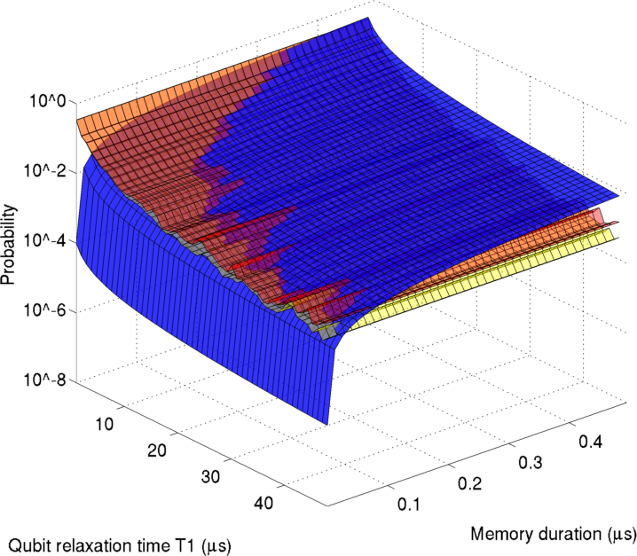
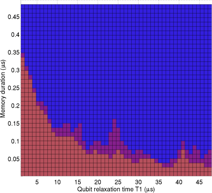
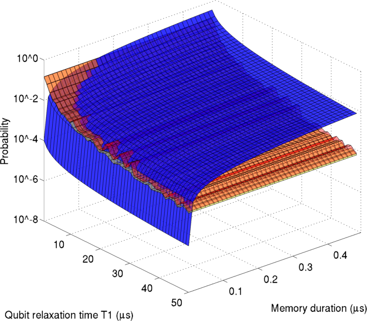
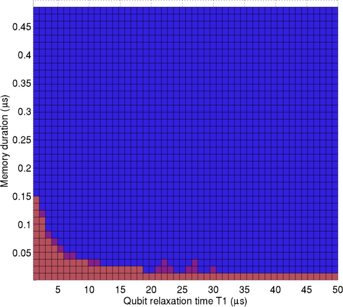
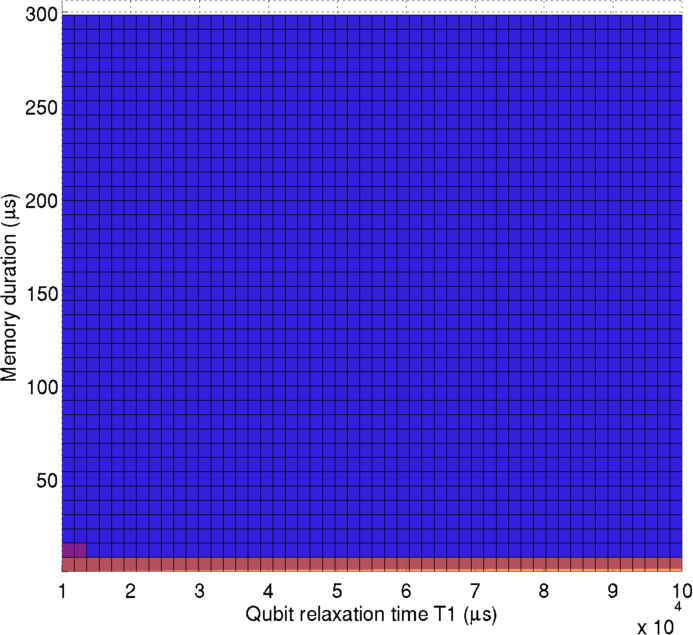
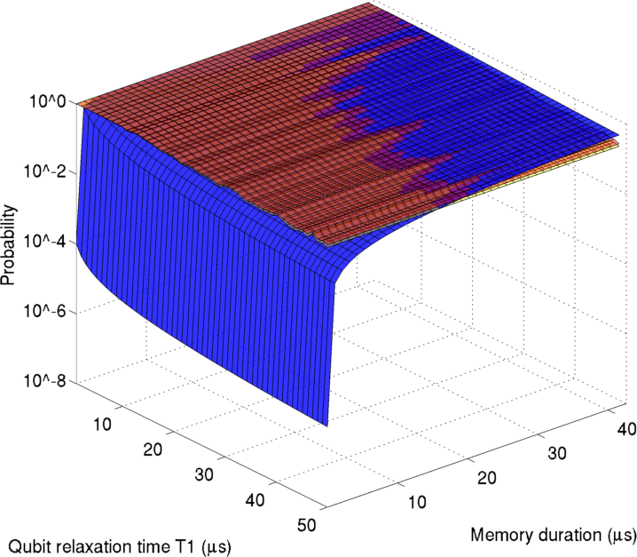
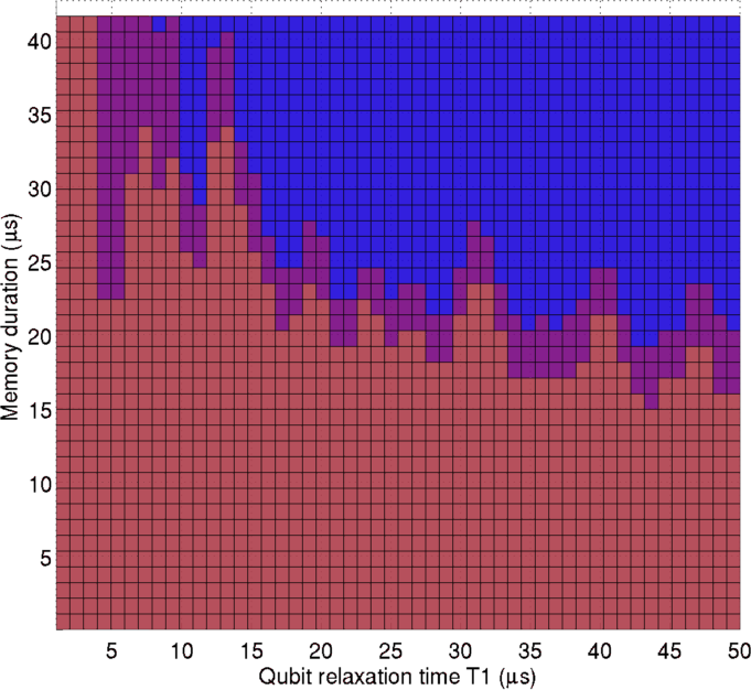
Since the Pauli-twirl approximation aligns well for phase-flip errors, we further compare its performance on bit-flip errors. Fig. 12 plots time (s) versus memory duration (s) versus the logical failure rate of a qubit encoded in in Surface-17 for the setting under (a) the Pauli-twirl approximation and (b) amplitude and phase damping. On the left, the blue surface represents the amplitude damping probability of an unencoded qubit in for a given time and memory duration. Since the qubit is in , phase damping does not apply. The yellow surface represents the logical error rate of an encoded qubit for a given time and surface code round time (see Table 3). The orange surface indicates the upper error bar of . For the yellow and orange surfaces, the encoded qubit undergoes the surface code three-round window time. For the blue surface, the unencoded qubit undergoes the given memory duration.
The region where the blue surface lies above the orange and yellow surfaces represents the regime where Surface-17 encoding improves the logical error rate of the qubit (similar to being below pseudothreshold). The region is larger in Fig. 12 (b) than Fig. 12 (a), indicating that Pauli twirling results in a pessimistic estimate of the logical error rate.
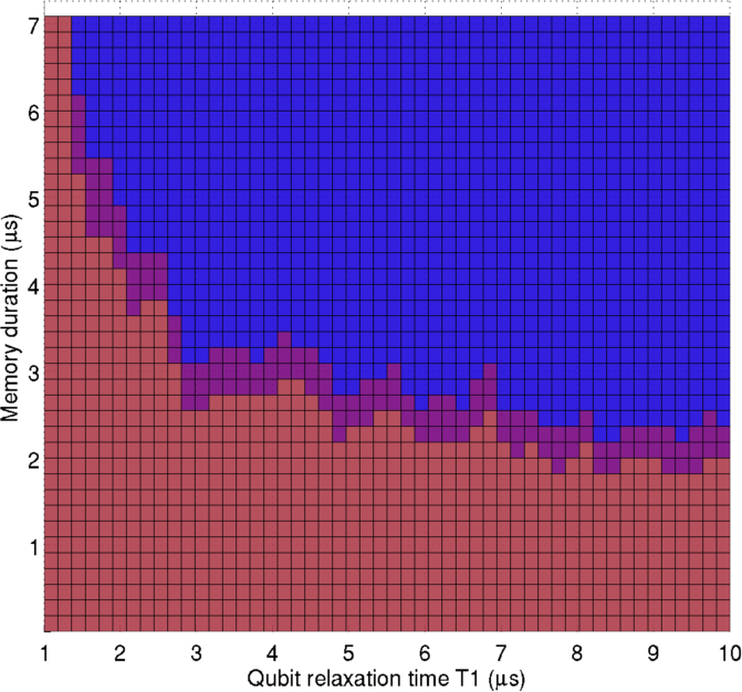
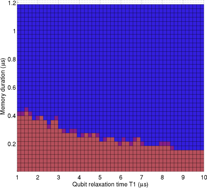
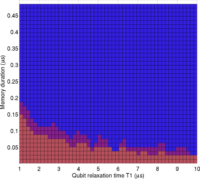
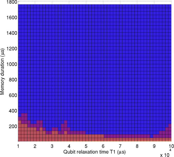
The 2D plots on the right are a view from the -axis. The blue and red regions indicate times (-axis) for which encoding a qubit in in Surface-17 reduces or increases, respectively, the logical error rate compared to an unencoded qubit in memory for a given duration (-axis). The purple region indicates the upper error bar of where the orange and blue surfaces cross in the 3D plots. Surface-17 again demonstrates superior performance under amplitude and phase damping compared to Pauli twirling. For example, for s, memory durations above 150 ns result in lower logical error rates for an encoded qubit than an unencoded qubit, while the Pauli-twirl approximation lowers error rates only for memory durations longer than 350 ns. At s, memory durations of 20 ns result in lower logical error rates, while Pauli twirling indicates lower rates at memory durations longer than 30–70 ns.
VI.3 Amplitude and Phase Damping
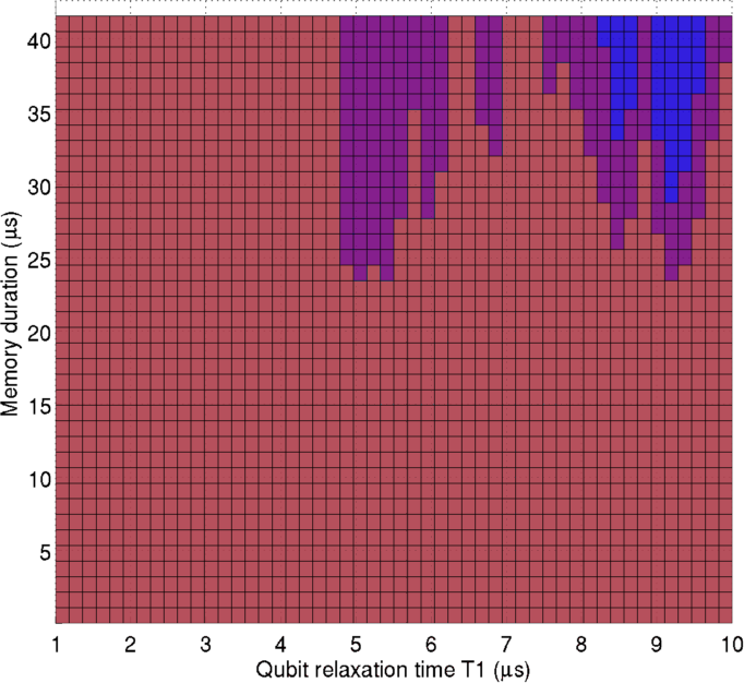
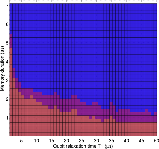
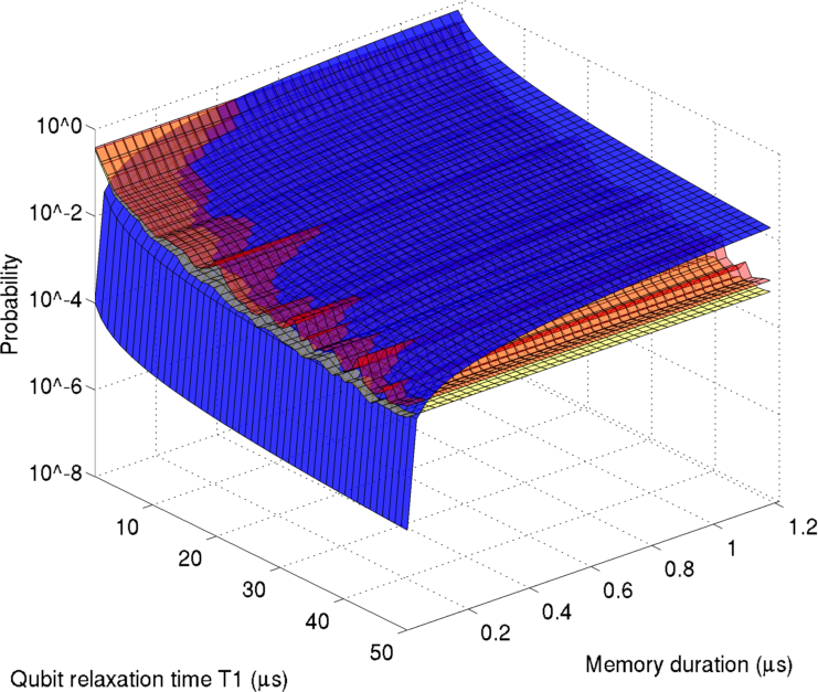
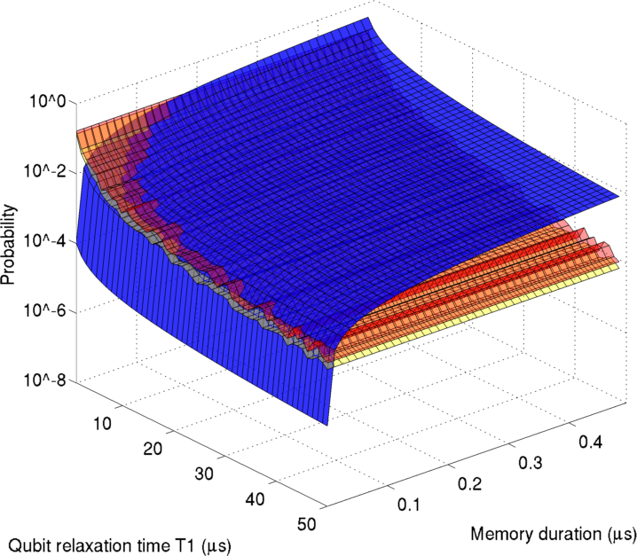
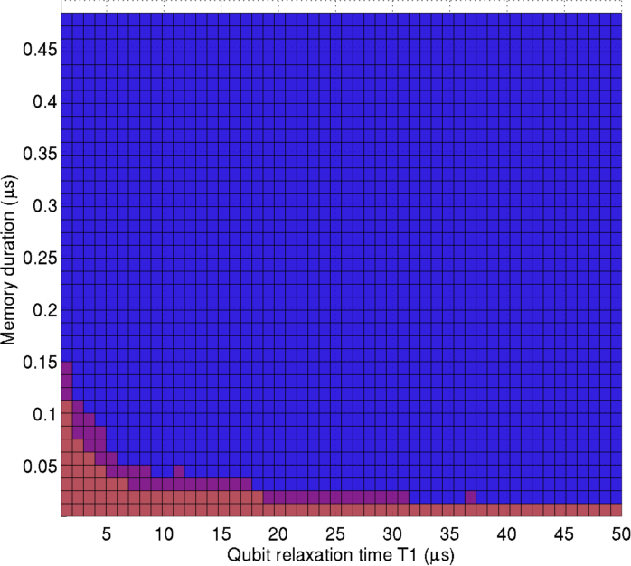
Figure 13 shows the same 2D plots for Surface-17 for all six architecture settings under amplitude and phase damping. For each architecture, the -axis ranges from 0 s to the time per surface code window. In all graphs, we see that as increases, encoding improves the logical error rate for a larger range of memory durations. This behavior is expected since the amplitude damping probability monotonically increases with memory duration.
In Fig. 13(a), at s we observe that for the parameters, encoding does not improve the logical error rate for any plotted memory duration. However, with 10 times faster gates (), we see performance improvement, as shown in Fig. 13(b). At s, encoding provides a better logical error rate than an unencoded qubit in memory for at least s. At s, shows no improvement with encoding, while exhibits improvements for memories of s or longer.
The setting accounts for 100 times faster preparation and measurement than and roughly 10 times faster gates. The faster times lead to significantly better performance under encoding. For example, at s and s in Fig. 13(d), the logical error rate decreases due to encoding for memory durations longer than ns and ns, respectively.
Comparing Fig. 13(c) and (d), we find CNOT time strongly influences performance. A CNOT gate is four times longer in than . The longer two-qubit gate time is reflected in the poorer performance of Surface-17 under parameters. At s, only indicates logical error rate reduction due to encoding at memory durations roughly 3 times longer than those required for .
Fig. 13(e) and (f) show similar results for the ion trap settings. While assumes 10 times faster CNOT gates, both and yield lower logical error rate upon encoding for a range of times. results in improvements for memory durations longer than 300–400 s, while results in improvements for memory durations above around 15 s.
In Figure 14, we plot qubit relaxation time (s) versus logical error rate (red) or amplitude damping probability (blue) for the six architecture settings (analogous to Fig. 11(b)). All plots assume a three-round memory duration. From the plots, the logical error rate for each architecture for a given time can be extracted. As gate times and times improve, the logical error rate decreases. An order of magnitude improvement in logical error rate can be obtained, for example, in improving gates time from those of to those of .
The plots also indicate that near-term experiments may be able to detect improved logical error rates due to encoding, providing experimental evidence of surface code error correction. For example, for s, no difference in the logical error rate can be detected between an encoded and unencoded qubit given settings and . However, exhibits differences on the order of one magnitude at times larger than s. Both and settings indicate significant difference in the logical error rate on an encoded versus unencoded qubit. In the case of both ion trap settings, a difference in logical error rate can be detected starting at s.
 |
 |
| (a) | (b) |
 |
 |
| (c) | (d) |
 |
 |
| (e) | (f) |
 |
 |
 |
| (a) | ||
 |
 |
 |
| (b) | ||
 |
 |
 |
| (c) | ||
 |
 |
 |
| (d) |
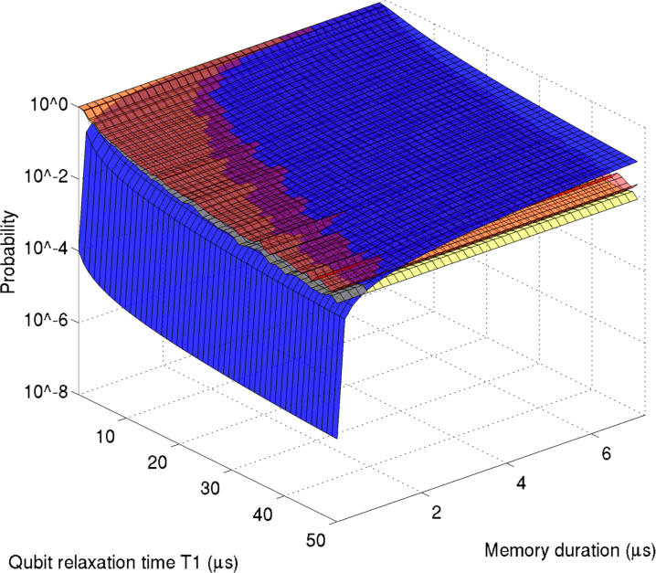
Figure 15 contains plots for times up to s for the four superconducting architectures. The left column contains 3D plots of time (s) versus memory duration (s) versus logical failure rate. The middle column contains 2D plots of time (s) versus memory duration (s). The right column contains 2D plots of time (s) versus logical failure rate.
We conclude that gate durations in the setting are too slow for Surface-17 to significantly decrease the logical error rate given realistic times (Fig. 15(a)). However, given gate durations between the and settings and current times of –s, encoding a qubit in Surface-17 results in significantly improved error rates over an unencoded qubit (Fig. 15(b)–(d)). For both superconductor and ion trap architectures, near-term experimental implementations could demonstrate surface code error correction of a single logical qubit, and measure signficiant improvements in the logical error rate. We find that previous estimates of 2.6–2.8 s times Ghosh et al. (2012) to achieve improved logical error rates are too high, and in fact at only 1 s time, the logical error rate can be improved using Surface-17.
VII Conclusion
We have analyzed three distance-three surface code layouts under realistic noise models. Under symmetric depolarizing noise, we find the pseudothreshold is slightly lower for Surface-13 as compared to Surface-17 and 25. We have compared the performance of Surface-17 simulated under a Pauli-twirl approximation and amplitude and phase damping. Our results show that Pauli twirling pessimistically estimates the logical bit-flip rate. Thus the surface code threshold under realistic noise may be significantly better than previously calculated.
We have also simulated the 17-qubit surface code under amplitude and phase damping for six architecture settings. While gate durations in the setting are too slow, gate durations between and with current times show improved logical error rates for a qubit encoded in Surface-17. For both superconductor and ion trap architectures, current state-of-the-art experiments may be able to demonstrate surface code error correction. For example, with around s and settings, logical error rates will improve by encoding in Surface-17 and may be detected in experiment. With settings, even shorter times will result in significant improvements with encoding.
Methods of approximating decoherence using Clifford gates have recently been shown to be more accurate than Pauli twirling Gutiérrez et al. (2013); Magesan et al. (2013). However, studies have only been conducted at the gate operation level as opposed to the circuit level of a given code. A direction for future work is to simulate these noise models on Surface-17 to compare to amplitude and phase damping. Another direction is to determine the performance of Surface-17 under leakage. Finally, development and simulation of realistic noise models for specific architectures will be important for guiding experimental surface code implementations.
Acknowledgements.
We are especially grateful to Dave Wecker for helping with the surface code and noise model implementations in LIQ. We thank Ken Brown, Leo DiCarlo, and Andrew Landahl for valuable discussions. We also thank Leo Kouwenhoven, Lieven Vandersypen, Austin Fowler, and Blake Johnson for useful feedback.References
- Fowler et al. (2012a) A. G. Fowler, M. Mariantoni, J. M. Martinis, and A. N. Cleland, Phys. Rev. A 86, 032324 (2012a).
- Lidar and Brun (2013) D. A. Lidar and T. A. Brun, Quantum error correction (Cambridge University Press, Cambridge, 2013).
- Bravyi and Kitaev (1998) S. Bravyi and A. Kitaev, “Quantum codes on a lattice with boundary,” (1998), arXiv:quant-ph/9811052.
- Kitaev (2003) A. Y. Kitaev, Ann. Phys. 303, 2 (2003).
- Raussendorf and Harrington (2007) R. Raussendorf and J. Harrington, Phys. Rev. Lett. 98, 190504 (2007).
- Fowler et al. (2009) A. G. Fowler, A. M. Stephens, and P. Groszkowski, Phys. Rev. A 80, 052312 (2009).
- Fowler et al. (2012b) A. G. Fowler, A. C. Whiteside, and L. C. L. Hollenberg, Phys. Rev. Lett. 108, 180501 (2012b), arXiv:1110.5133 [quant-ph].
- Wang et al. (2011) D. S. Wang, A. G. Fowler, and L. C. L. Hollenberg, Phys. Rev. A 83, 020302 (2011).
- Stephens (2013) A. M. Stephens, “Fault-tolerant thresholds for quantum error correction with the surface code,” (2013), arXiv:1311.5003v1 [quant-ph].
- Helmer et al. (2009) F. Helmer, M. Mariantoni, A. G. Fowler, J. von Delft, E. Solano, and F. Marquardt, EPL (Europhysics Letters) 85, 50007 (2009).
- DiVincenzo (2009) D. P. DiVincenzo, Physica Scripta 2009, 014020 (2009).
- Kielpinski et al. (2002) D. Kielpinski, C. R. Monroe, and D. J. Wineland, Nature 417, 709 (2002).
- Monroe et al. (2014) C. Monroe, R. Raussendorf, A. Ruthven, K. R. Brown, P. Maunz, L.-M. Duan, and J. Kim, Phys. Rev. A 89, 022317 (2014).
- Merrill et al. (2011) J. T. Merrill, C. Volin, D. Landgren, J. M. Amini, K. Wright, S. C. Doret, C.-S. Pai, H. Hayden, T. Killian, D. Faircloth, K. R. Brown, A. W. Harter, and R. E. Slusher, New J. of Phys. 13, 103005 (2011).
- Wright et al. (2013) K. Wright, J. Amini, D. Faircloth, C. Volin, S. Doret, H. Hayden, C.-S. Pai, D. Landgren, D. Denison, T. Killian, R. Slusher, and A. Harter, (2013), arXiv:1210.3655 [quant-ph].
- Barends et al. (2014) R. Barends, J. Kelly, A. Megrant, A. Veitia, D. Sank, E. Jeffrey, T. C. White, J. Mutus, A. G. Fowler, B. Campbell, Y. Chen, Z. Chen, B. Chiaro, A. Dunsworth, C. Neill, P. OMalley, P. Roushan, A. Vainsencher, J. Wenner, A. N. Korotkov, A. N. Cleland, and J. M. Martinis, Nature 508 (2014), arXiv:1402.4848 [quant-ph].
- Gottesman (1999) D. Gottesman, in Proc. of the XXII Intl. Colloq. on Group Theoretical Methods in Physics (GROUP22), edited by S. P. Corney, R. Delbourgo, and P. D. Jarvis (Intl. Press, 1999) pp. 32–43, arXiv:quant-ph/9611027.
- Aaronson and Gottesman (2004) S. Aaronson and D. Gottesman, Phys. Rev. A 70, 052328 (2004).
- Silva et al. (2008) M. Silva, E. Magesan, D. W. Kribs, and J. Emerson, Phys. Rev. A 78, 012347 (2008).
- Nielsen and Chuang (2000) M. A. Nielsen and I. L. Chuang, Quantum computation and quantum information (Cambridge University Press, 2000).
- Ghosh et al. (2012) J. Ghosh, A. G. Fowler, and M. R. Geller, Phys. Rev. A 86, 062318 (2012).
- Magesan et al. (2013) E. Magesan, D. Puzzuoli, C. E. Granade, and D. G. Cory, Phys. Rev. A 87, 012324 (2013).
- Puzzuoli et al. (2014) D. Puzzuoli, C. Granade, H. Haas, B. Criger, E. Magesan, and D. G. Cory, Phys. Rev. A 89, 022306 (2014), arXiv:1309.4717v1 [quant-ph].
- Gutiérrez et al. (2013) M. Gutiérrez, L. Svec, A. Vargo, and K. R. Brown, Phys. Rev. A 87, 030302 (2013).
- Fowler (2013a) A. G. Fowler, Phys. Rev. A 88, 042308 (2013a), arXiv:1308.6642v1 [quant-ph].
- Fowler and Martinis (2014) A. G. Fowler and J. M. Martinis, (2014), arxiv:1401.2466v3[quant-ph].
- Jouzdani et al. (2014) P. Jouzdani, E. Novais, I. S. Tupitsyn, R. Raussendorf, and E. R. Mucciolo, “Fidelity threshold of the surface code beyond single-qubit error models,” (2014), arXiv:1401.6540 [quant-ph].
- Bombin and Martin-Delgado (2007) H. Bombin and M. Martin-Delgado, Phys. Rev. A 76, 012305 (2007).
- Horsman et al. (2012) C. Horsman, A. G. Fowler, S. Devitt, and R. V. Meter, New Journal of Physics 14, 123011 (2012).
- Wecker and Svore (2014) D. Wecker and K. M. Svore, “LIQ: A software design architecure and domain-specific language for quantum computing,” (2014), arXiv:1402.4467 [quant-ph].
- Edmonds (1965a) J. Edmonds, Canad. J. Math. 17 (1965a).
- Edmonds (1965b) J. Edmonds, J. Res. Nat. Bur. Standards B 69 (1965b).
- Fowler (2013b) A. G. Fowler, (2013b), arXiv:1307.1740 [quant-ph].
- Fowler (2013c) A. G. Fowler, “Optimal complexity correction of correlated errors in the surface code,” (2013c), arXiv:1310.0863v1 [quant-ph].
- Sarvepalli et al. (2009) P. K. Sarvepalli, A. Klappenecker, and M. Rötteler, Proc. R. Soc. A 465, 1645 (2009).
- Svore et al. (2006) K. M. Svore, A. W. Cross, I. L. Chuang, and A. V. Aho, Quant. Inf. Comp. 6, 193 (2006).
- Svore et al. (2005) K. Svore, B. M. Terhal, and D. DiVincenzo, Phys. Rev. A 72, 022317 (2005).
- DiCarlo et al. (2010) L. DiCarlo, M. D. Reed, L. Sun, B. R. Johnson, J. Chow, J. M. Gambetta, L. Frunzio, S. M. Girvin, M. H. Devoret, and R. J. Schoelkopf1, Nature 467, 574 (2010).
- Chow et al. (2010) J. M. Chow, L. DiCarlo, J. M. Gambetta, F. Motzoi, L. Frunzio, S. M. Girvin, , and R. J. Schoelkopf1, Phys. Rev. A 82, 040305 (2010).
- Chow et al. (2013) J. M. Chow, J. M. Gambetta, E. Magesan, S. J. Srinivasan, A. W. Cross, D. W. Abraham, N. A. Masluk, B. R. Johnson, C. A. Ryan, and M. Steffen, “Implementing a strand of a scalable fault-tolerant quantum computing fabric,” (2013), arXiv:1311.6330 [quant-ph].
- Harty et al. (2014) T. P. Harty, D. T. C. Allcock, C. J. Ballance, L. Guidoni, H. A. Janacek, N. M. Linke, D. N. Stacey, and D. M. Lucas, “High-fidelity preparation, gates, memory and readout of a trapped-ion quantum bit,” (2014), arXiv:1403.1524 [quant-ph].
- Häffner et al. (2008) H. Häffner, C. Roos, and R. Blatt, Physics Reports 469, 155 (2008).
- Noek et al. (2013) R. Noek, G. Vrijsen, D. Gaultney, E. Mount, T. Kim, P. Maunz, and J. Kim, Opt. Lett. 38, 4735 (2013).
- Brown (2013) K. R. Brown, private communication (2013).
- Fowler et al. (2012c) A. G. Fowler, A. C. Whiteside, and L. C. L. Hollenberg, Phys. Rev. A 86, 042313 (2012c), arXiv:1202.5602 [quant-ph].