Non-Abelian topological insulators from an array of quantum wires
Abstract
We suggest a construction of a large class of topological states using an array of quantum wires. First, we show how to construct a Chern insulator using an array of alternating wires that contain electrons and holes, correlated with an alternating magnetic field. This is supported by semi-classical arguments and a full quantum mechanical treatment of an analogous tight-binding model. We then show how electron-electron interactions can stabilize fractional Chern insulators (Abelian and non-Abelian). In particular, we construct a non-Abelian parafermion state. Our construction is generalized to wires with alternating spin-orbit couplings, which give rise to integer and fractional (Abelian and non-Abelian) topological insulators. The states we construct are effectively two-dimensional, and are therefore less sensitive to disorder than one-dimensional systems. The possibility of experimental realization of our construction is addressed.
pacs:
73.21.Hb,71.10.Pm,73.43.-f,05.30.PrI Introduction
The integer quantum Hall effect (IQHE) Klitzing et al. (1980) was discovered in two-dimensional (2D) systems subjected to a strong perpendicular magnetic field. The quantized conductance is a consequence of the emergence of a topological number Thouless et al. (1982), known as the Chern number. Haldane Haldane (1988) showed that a Graphene-like material which breaks time-reversal symmetry due to an alternating (zero average) magnetic field may have a non-zero Chern number as well. These types of materials, which have a non-zero Hall conductance with a zero total magnetic flux, are referred to as Chern insulators (CI).
The existence of edge modes Halperin (1982) in the QHE can be understood in various ways. In particular, one can understand the presence of edge modes by studying the classical curved trajectories of electrons in a magnetic field. In fact, it is possible to construct a semi-classical theory for a specific set of Chern insulators as well. Consider a system consisting of electrons and holes (whose masses differ in sign). In the presence of a magnetic field, their classical trajectories are curved in opposite directions. If however, the electrons and the holes experience opposite magnetic fields, the trajectories will be curved in the same direction. One can imagine constructing a Chern-insulator by separating the plane into regions which contain only holes and only electrons. If the magnetic field is opposite in the two regions, the classical trajectories will be similar to those of electrons in a uniform magnetic field. This suggests that, upon quantization, this system should have a non-zero Chern number Note (1), despite the fact that the total magnetic flux vanishes.
Motivated by this semi-classical picture, we will study in this work an effectively 2D system which consists of alternating wires that contain electrons and holes. Approaching the 2D problem from the quasi-one-dimensional (Q1D) limit enables a full quantum-mechanical analysis, and an analytic treatment of interaction effects using the bosonization technique.
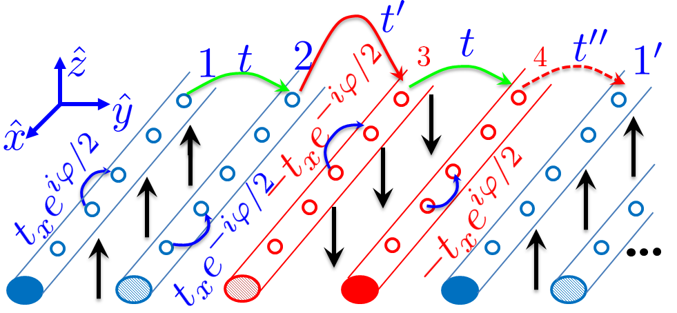
Ref. Yakovenko (1991); Sondhi and Yang (2001) argues that it is possible to understand the IQHE by considering a set of weakly coupled parallel wires. First, we will show that one can use an array of wires to construct a CI as well (see Fig. 1a). We then introduce a tight-binding version of this model and obtain a phase diagram, showing the Chern number as a function of the model parameters.
Kane et al. Kane et al. (2002) generalized the wires approach to the Abelian fractional quantum Hall effect (FQHE) using the bosonization technique. We will generalize our construction to a fractional CI (FCI) as well.
To do so, we introduce composite particles. This transformation maps the electrons and holes at 1/3 filling to composite particles at filling 1. The possibility of a FCI has recently been discussed quite extensively in the literature Parameswaran et al. (2013). Numerical investigations Tang et al. (2011); Sun et al. (2011); Neupert et al. (2011); Sheng et al. (2011); Wang et al. (2012); Regnault and Bernevig (2011) of lattice models with nearly flat bands presented strong evidence for FCI states. More general approaches, connecting the properties of the known FQHE states and analogous FCI states, were found Qi (2011); Parameswaran et al. (2012). Here we present an alternative analytic approach to the subject, which may be applicable in experiments.
Teo & Kane Teo and Kane (2011) expand the approach of Kane et al. (2002) to non-Abelian states. We will see that our results can be generalized to the non-Abelian case as well, and we will provide a detailed construction of a state similar to the Read-Rezay state. This state supports Fibonacci anyons, which may be used for universal quantum computation Freedman et al. (2002a, b).
Using an analogy between a magnetic field and a spin-orbit coupling (in the direction only), we will construct a topological insulator from an array of wires using an alternating spin-orbit coupling. It will then be straightforward to generalize the above model to a fractional topological insulator (FTI) Levin and Stern (2009). Other realizations of FTI states were discussed in Ref. Chen and Yang (2012); Furukawa and Ueda (2014); Ghaemi et al. (2012); Neupert et al. (2011b); Repellin et al. (2014).
II Wires construction of a CI
Motivated by the above semi-classical picture, we have designed the wires construction, shown in Fig. 1a. In each unit cell there are four different wires. We tune the wires’ chemical potentials such that wires 1 and 2 of each unit cell are near the bottom of the band, and wires 3 and 4 are near the top. Effectively, we have alternating pairs of wires that contain electrons and holes. A positive (negative) magnetic field is introduced between the pairs of electron (hole) wires. This is a Q1D version of the semi-classical picture we described above.
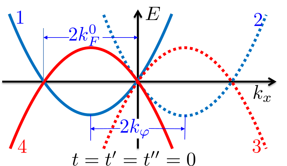
blackFor illustration and simplicity it is convenient to choose a gauge in which the vector potential points at the direction.We can tune the wires’ bands in such a way that all their crossing points match in energy. In this case, the energy spectra are similar to those depicted in Fig. 1b. We define as the Fermi momenta in the absence of an external magnetic field. is the shift of the parabolas due to the magnetic fields (see Fig. 1b).
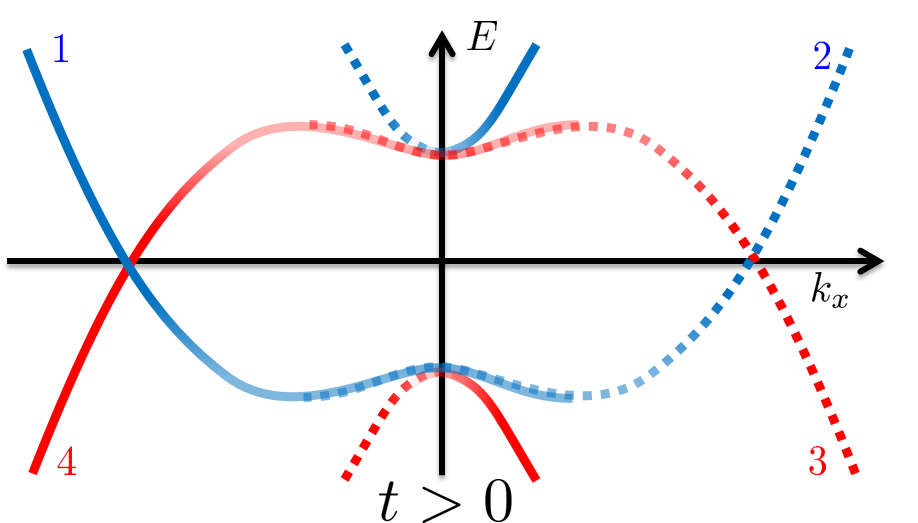
If in addition, neighboring wires of the same type are weakly tunnel coupled (with an amplitude ), a gap opens between parabolas 1 and 2, and parabolas 3 and 4. The spectrum in this case is depicted in Fig. 1c.
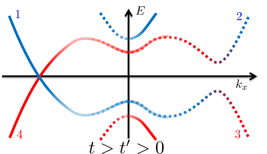
Introducing now a coupling between the electrons and holes inside a unit cell (), a gap will open at , and we arrive at the spectrum depicted in Fig. 1d. If we now switch on small tunneling between different unit cells (), the coupling between the edges decays exponentially with the sample width, and in the thermodynamic limit we expect to find gapless edge states. The observation of gapless edge states indicates that there is a non-zero Chern number. To show this explicitly, we have constructed a 2D tight-binding model, which is the lattice version of the above continuous model. The tight binding model enables an exact derivation of phase diagram, showing the Chern number as a function of the model parameters. For more details see the supplemental material Sup , where the tight binding model is defined, and its phased diagram is derived, ensuring that the results of the above discussion are valid. We note that, by construction, our model has only a single chiral edge mode, leading to the fact that the model can only have Chern numbers . Generalization to larger Chern numbers is a possible interesting extension.
III FCI
The wires construction invites us to add interactions and use bosonization techniques, similar to those used in Kane et al. (2002); Teo and Kane (2011). This allows us to generalize the above results to FCI states. In the presence of interactions, multi-electron processes may open a gap even if the Fermi point of the left movers is not equal to the Fermi points of the right movers Kane et al. (2002); Teo and Kane (2011); Oreg et al. (2013); Klinovaja and Loss (2013a).
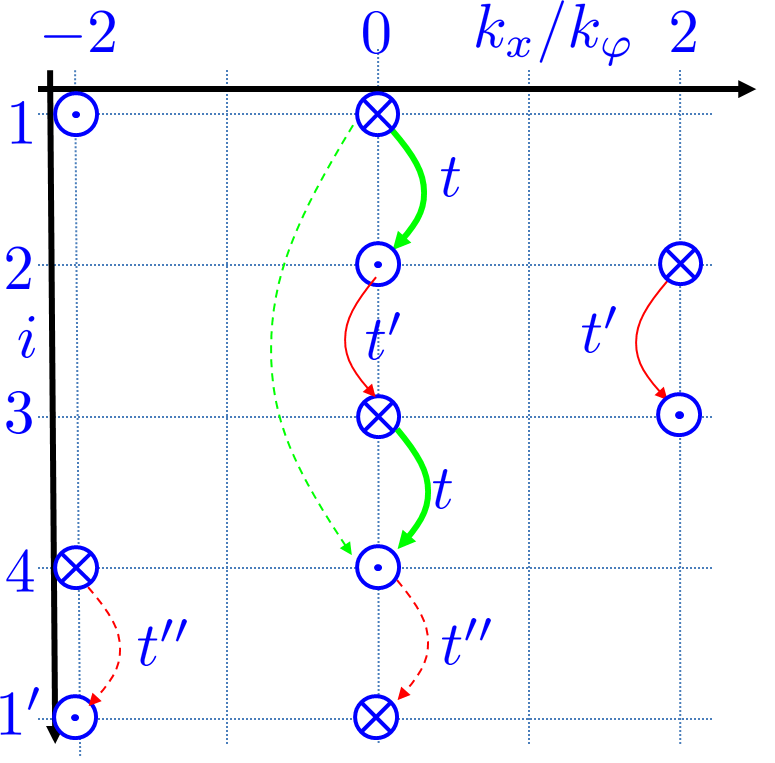
To understand the required conditions for a gap opening due to multi-electron scattering processes, it is useful to present the spectra of Fig. 1b in an alternative way. Instead of plotting the entire spectrum of the wires together, we plot only the Fermi points as a function of the wire index. Soon, we will linearize the spectra around these points. A cross () denotes the Fermi point of a right mover, and a dot () denotes the Fermi point of a left mover. Before analyzing the fractional case, it is useful to revisit the simple case. We will see that the main results of the tight binding model arise naturally in the bosonization framework. Fig. 2a shows the diagram that corresponds this case (Fig. 1b).
Linearizing the spectrum around the Fermi-points of each wire, and using the standard bosonization procedure, we define the two chiral bosonic fields, and , for each wire. In terms of these, the fermionic operators are
Without interactions, a momentum conserving single-electron tunneling between the wires (denoted in Fig. 2a by an arrow) is possible only when the left and right movers of adjacent wires are at the same point in -space. The single-electron tunneling operators between adjacent wires (denoted in Fig. 2a by green, red, and dashed red arrows) are
| (1) |
We switch on the operators in the following way: first, we switch on a small . Since this is a relevant operator, it gaps out the spectrum near . Then, we switch on smaller electron-hole couplings . The terms and gap out the rest of the spectrum, leaving a gapless edge mode. As we discussed before, this indicates that there is a non-zero Chern number. Note that the terms and contain fields which are conjugate to those already pinned by . Strong quantum fluctuations are therefore expected to suppress these terms.
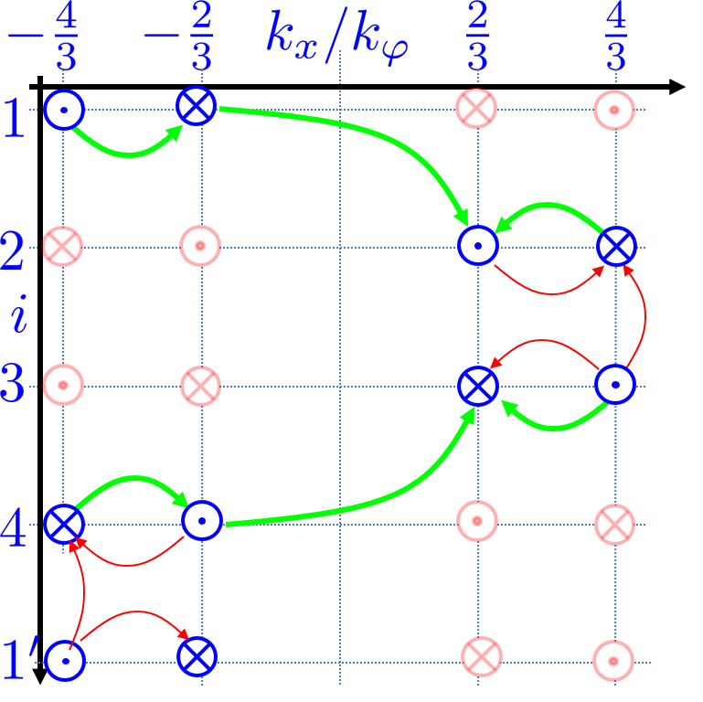
We now turn to generalize this to Laughlin-like FCI states, with a filling factor , where is a non-negative integer. For example, the -vector pattern of the wires with is shown in blue in Fig. 2b. In this case, multi-electron processes are expected to gap out the system (except for the edges). To see this, it is enlightening to define new chiral fermion operators
| (2) |
with
| (3) |
and A direct calculation of the commutation relations of the -fields show that they have an additional factor of compared the -fields. This gives an extra (trivial) phase factor in the anti-commutation relation of the ’s compared to the ’s, insuring that the ’s are fermionic operators. In addition, it can easily be checked that the resulting structure of the ’s is identical to that of the ’s in the case of (Fig. 2a), so that can be regarded as a fermionic field with . This procedure can therefore be interpreted as an attachment of quantum fluxes to each electron (cf. Jain’s construction of composite fermions Jain (2007)).
Repeating the analysis of the case, we can now write single tunneling operators, identical to those found in Eq. (1) (replacing , with new tunneling amplitudes , and ). In terms of the original electrons, these operators describe the multi-electron processes shown in Fig. 2b. Note that when the interactions are strong enough, these operators become relevant Kane et al. (2002); Teo and Kane (2011); Oreg et al. (2013). From here, the process is identical to the integer case. The gap due to the tunneling operators ensures that competing processes (for example, single electron tunneling between wires 2 and 3, or 4 and 1’) are suppressed, as they contain fields that are conjugate to the fields pinned by (which is dominant by our construction).
IV Non-Abelian FCI
As the discussion above shows, the wires construction allowed us to create Abelian fractional Chern insulators. Ref. Teo and Kane (2011) constructed non-Abelian QHE states by enlarging the unit cell, and taking a non-uniform magnetic field inside each unit cell. By our construction, any non-Abelian state constructed by Teo and Kane (2011) can be generalized to the CI case. To do so, one can take two unit cells from the construction in Ref. Teo and Kane (2011), reverse the magnetic field of the second unit cell, and use holes instead of electrons. However, the lack of a total magnetic flux in our system enables a simpler construction of non-Abelian states, which don’t have a direct analog in the QHE. We now show that a slight modification of the procedure that enabled the construction of Laughlin-like states may lead to non-Abelian states. We will focus here on a state similar to the Read-Rezay state. Generalization to other non-Abelian states is possible.
To obtain a parafermion state, we take , and construct the operators. Let us start in the special point where and the coupling between and are tuned to have exactly the same value, denoted by (at the end, when the topological nature of our construction will be revealed, this strict requirement can be relaxed, as long as the bulk gap doesn’t close). It can be shown (see supplemental material Sup for more technical details) that under these assumptions our problem can be mapped to the self-dual Sine-Gordon model, which was studied in Ref. Lecheminant et al. (2002); Mong et al. (2013). Specifically, it was shown that this model is mapped to a critical parafermionic field.
We have established that any unit cell has two counter propagating parafermionic fields (around ), and two counter propagating charge modes at . As earlier, we can in principle gap out the spectrum by switching on specific coupling terms between different unit cells, leaving eventually a Laughlin-like charge mode and a parafermion mode at the edge of the sample. However, in order to leave a chiral parafermion mode we need to consider quasiparticle tunneling terms, which are not allowed in the present construction Mong et al. (2013); Sup . This technical problem is easily solved by adding an additional flavor quantum number to each wire, which allows one to effectively create a thin FQHE state in each unit cell (see supplemental material Sup ). This way, in addition to supporting gapless parafermion modes in each unit cell, our construction enables their coupling. We point out that the above construction is related to the bilayer QHE system presented by Ref. Vaezi and Barkeshli (2014). We note that while the non-Abelian part is the same as the non-Abelian part of the Read-Rezay state, the charge mode is different.
V Topological insulators from the wires approach
The entire analysis presented here can also be carried out for \textcolorblackspinful electrons if one introduces spin-orbit interactions (in the direction only). This can be done if an alternating electric field is introduced instead of an alternating magnetic field. For example, the electric field can be tuned in such a way that the spin-orbit coupling is positive at wires 1 and 4, and negative at wires 2 and 3. Fig. 2b shows the appropriate Fermi-momenta corresponding to (in blue for spin up and light red for spin down). If one considers only processes which conserve , we get a simple construction for integer, Laughlin-like, and non-Abelian topological insulators Levin and Stern (2009), which are simply two copies of the FCI states discussed above (with opposite chiral modes for the different spin species). If we now introduce small time-reversal invariant terms which violate conservation (but do not close the gap), the helical modes remain protected.
VI Generalization
The approach we present here can be extended \textcolorblackto hierarchical Abelian states, as well as other non-Abelian states (such as a Moore-Read-like state). One can also study the effects of proximity to a superconductor, which is expected to yield other non-Abelian states. A detailed further study of these constructions will be performed in the future.
VII Experimental realizations
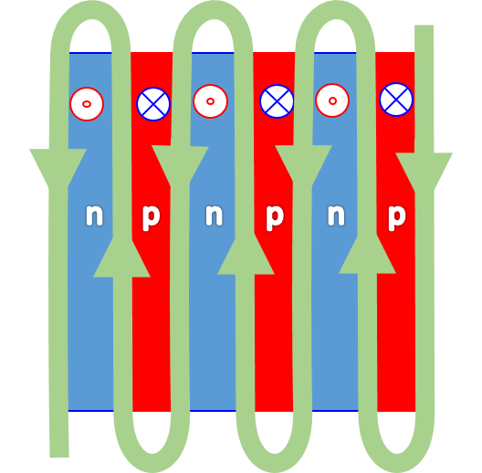
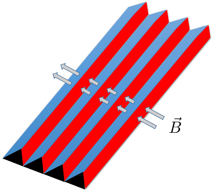
The above theoretical construction may also be applicable in experiments with superlattices that realize the particle-hole structure we suggest. The alternating magnetic field can be generated, for example, using a snake-like wire Zel , as shown in Fig. 3a (for more technical details see the supplemental material Sup ), or using an array of V-grooves Pal , as shown in Fig. 3b. We note that stripes with an alternating magnetic field can also be realized in cold atom systems Aidelsburger et al. (2011).
By coupling many (or maybe only a few) wires together we get an effective 2D system. Our construction lacks the disadvantages of fractional 1D states Oreg et al. (2013); Klinovaja and Loss (2013a), which are not topologically protected Fidkowski and Kitaev (2011); Turner et al. (2011), and the need to invoke proximity to a superconductor and a strong magnetic field simultaneously in 2D Lindner et al. (2012); Vaezi (2013); Mong et al. (2013). As long as the width of the edge modes is smaller than the sample width, it behaves practically as a topologically protected 2D system.
Acknowledgements.
Acknowledgments We would like to thank Arbel Haim, Erez Berg, Eran Sela, Ady Stern, Netanel Lindner, Anna Kesselman, Jason Alicea, Gabriel Zeltzer and Alexander Palevski for useful discussions. We acknowledge the partial support of the Israeli Science Foundation (ISF), the Minerva foundation, the WIS-TAMU grant, and the European Research Council under the European Community’s Seventh Framework Program (FP7/2007-2013)/ERC Grant agreement No. 340210.References
- Klitzing et al. (1980) K. Klitzing, G. Dorda, and M. Pepper, Physical Review Letters 45, 494 (1980).
- Thouless et al. (1982) D. Thouless, M. Kohmoto, M. Nightingale, and M. den Nijs, Physical Review Letters 49, 405 (1982).
- Haldane (1988) F. D. M. Haldane, Physical Review Letters 61, 2015 (1988).
- Halperin (1982) B. Halperin, Physical Review B 25, 2185 (1982).
- Note (1) Note that since the transition between different regions is affected by the details of the model, we expect the Bohr-Sommerfeld quantization condition to provide bands which are not flat in general.
- Yakovenko (1991) V. Yakovenko, Physical Review B 43, 11353 (1991).
- Sondhi and Yang (2001) S. Sondhi and K. Yang, Physical Review B 63, 054430 (2001).
- Kane et al. (2002) C. Kane, R. Mukhopadhyay, and T. Lubensky, Physical Review Letters 88, 036401 (2002).
- Parameswaran et al. (2013) S. A. Parameswaran, R. Roy, and S. L. Sondhi, Comptes Rendus Physique 14, 816 (2013).
- Tang et al. (2011) E. Tang, J.-W. Mei, and X.-G. Wen, Physical Review Letters 106, 236802 (2011).
- Sun et al. (2011) K. Sun, Z. Gu, H. Katsura, and S. Das Sarma, Physical Review Letters 106, 236803 (2011).
- Neupert et al. (2011) T. Neupert, L. Santos, C. Chamon, and C. Mudry, Physical Review Letters 106, 236804 (2011).
- Sheng et al. (2011) D. N. Sheng, Z.-C. Gu, K. Sun, and L. Sheng, Nature communications 2, 389 (2011).
- Wang et al. (2012) Y.-F. Wang, H. Yao, Z.-C. Gu, C.-D. Gong, and D. N. Sheng, Physical Review Letters 108, 126805 (2012).
- Regnault and Bernevig (2011) N. Regnault and B. A. Bernevig, Physical Review X 1, 021014 (2011).
- Qi (2011) X.-L. Qi, Physical Review Letters 107, 126803 (2011).
- Parameswaran et al. (2012) S. A. Parameswaran, R. Roy, and S. L. Sondhi, Physical Review B 85, 241308 (2012).
- Teo and Kane (2011) J. C. Y. Teo and C. L. Kane, (2011), arXiv:1111.2617.
- Freedman et al. (2002a) M. H. Freedman, M. J. Larsen, and Z. Wang, Communications in Mathematical Physics 228, 177 (2002a).
- Freedman et al. (2002b) M. H. Freedman, M. Larsen, and Z. Wang, Communications in Mathematical Physics 227, 605 (2002b).
- Levin and Stern (2009) M. Levin and A. Stern, Physical Review Letters 103, 196803 (2009).
- Chen and Yang (2012) H. Chen and K. Yang, Physical Review B 85, 195113 (2012).
- Furukawa and Ueda (2014) S. Furukawa and M. Ueda, (2014), arXiv:1402.6860 .
- Ghaemi et al. (2012) P. Ghaemi, J. Cayssol, D. N. Sheng, and A. Vishwanath, Physical Review Letters 108, 266801 (2012).
- Neupert et al. (2011b) T. Neupert, L. Santos, S. Ryu, C. Chamon, and C. Mudry, Physical Review B 84, 165107 (2011b).
- Repellin et al. (2014) C. Repellin, B. A. Bernevig, and N. Regnault, (2014), arXiv:1402.2652 .
- Oreg et al. (2013) Y. Oreg, E. Sela, and A. Stern, (2013), arXiv:1301.7335.
- Klinovaja and Loss (2013a) J. Klinovaja and D. Loss, (2013a), arXiv:1311.3259.
- Lindner et al. (2012) N. H. Lindner, E. Berg, G. Refael, and A. Stern, Physical Review X 2, 041002 (2012).
- Vaezi (2013) A. Vaezi, (2013), arXiv:1307.8069.
- Mong et al. (2013) R. S. K. Mong, D. J. Clarke, J. Alicea, N. H. Lindner, P. Fendley, C. Nayak, Y. Oreg, A. Stern, E. Berg, K. Shtengel, and M. P. A. Fisher, (2013), arXiv:1307.4403.
- Klinovaja and Loss (2013b) J. Klinovaja and D. Loss, (2013b), arXiv:1305.1569.
- Klinovaja and Loss (2013c) J. Klinovaja and D. Loss, Physical Review Letters 111, 196401 (2013c).
- Neupert et al. (2014) T. Neupert, C. Chamon, C. Mudry, and R. Thomale, (2014), arXiv:1403.0953.
- (35) See supplemental material.
- Jain (2007) J. K. Jain, Composite Fermions (Cambridge University Press, 2007) p. 560.
- Lecheminant et al. (2002) P. Lecheminant, A. O. Gogolin, and A. A. Nersesyan, Nuclear Physics B 639, 502 (2002).
- Vaezi and Barkeshli (2014) A. Vaezi and M. Barkeshli, (2014), arXiv:1403.3383.
- (39) G. Zeltzer (private communication).
- (40) A. Palevski (private communication).
- Aidelsburger et al. (2011) M. Aidelsburger, M. Atala, S. Nascimbène, S. Trotzky, Y.-A. Chen, and I. Bloch, Physical Review Letters 107, 255301 (2011).
- Fidkowski and Kitaev (2011) L. Fidkowski and A. Kitaev, Physical Review B 83, 075103 (2011).
- Turner et al. (2011) A. M. Turner, F. Pollmann, and E. Berg, Physical Review B 83, 075102 (2011).
Supplemental Material
This supplemental material introduces the tight binding version of the wires construction. A detailed derivation of the phase diagram is presented. In addition, we show explicitly how our construction of a non-Abelian state is mapped to the self-dual Sine-Gordon model, and provide technical details about the experimental realization suggested at the concluding part of the main text.
Tight binding model
To show explicitly that the model is topologically non-trivial, we have constructed a 2D tight-binding model, which is the lattice version of the wires construction defined in the main text.
The unit cell of the model is larger than the basic unit cell of the underlying square lattice: each unit cell contains 4 points, corresponding to the 4 different wires in Fig. 1a of the main text. Each point is characterized by , the location of the unit cell (measured in units of the lattice spacing ), and an index which labels the sites inside the unit cell.
We introduce the nearest neighbor tunneling amplitudes: , described in Fig. 1a of the main text. The phase , with , is the Peierls phase associated with the alternating external magnetic field. It is related to the flux in a basic unit cell: , where . In addition, we introduce a mass term (not related to the physical mass of the particle), which adds a constant energy () for electrons (holes). The sign of is equal to the sign of . Similar to Haldane’s original model, and tune the system into and out of the topological phases. For simplicity, we restrict ourselves to the case .
We define the annihilation operators, , in terms of which the tight binding Hamiltonian described in the main text is a sum of the following terms:
| (4) |
| (5) |
| (6) |
| (7) | ||||
with and .
It is convenient to write the Hamiltonian in Fourier space, where it takes the form with , and
| (8) |
We define a new gauge:
| (9) |
in terms of which the Hamiltonian takes the simple form
| (10) |
In writing the Hamiltonian this way we divide the matrix into four blocks, where () are Pauli matrices which operate within the blocks separately, while are Pauli matrices which operate on the outer matrix of blocks.
Symmetries
It is easy to check that the Hamiltonian in Eq. (10) has a particle-hole symmetry,
| (11) |
where . The particle-hole symmetry implies that the bands are symmetric around . Therefore, any crossing of the upper and lower bands must be at . Additionally, we have an inversion symmetry,
| (12) |
where . The crossings therefore must either be at the high symmetry points, satisfying , or come in pairs.
Crossing points
For convenience, we write the Bloch Hamiltonian, Eq. (10), in the form
| (13) |
In terms of these, the spectrum is
| (14) |
Using this explicit form, it is now easy to find that the upper and lower bands cross each other at the high symmetry points when
| (15) |
These crossing points signal a topological phase transition between a topologically trivial phase and a phase with a non-zero Chern number. The resulting phase diagram, showing the Chern number as a function of and is depicted in Fig. 4.
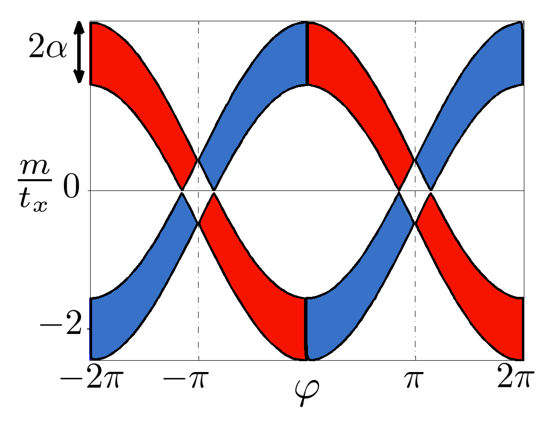
There are additional crossings at the points , whose locations in -space depend on . Since these crossings are not at the high symmetry points, they must come in pairs.
If we add a small non-zero chemical potential , the bands cross the chemical potential when
| (16) |
The topologically trivial and non-trivial insulating phases are now separated by metallic phases. The transitions between the metallic and insulating phases are described by Eq. (16).
In the same way, metallic regions appear near .
Mapping to the self-dual Sine-Gordon model
In terms of the bosonized fields, the scattering terms presented in the main text are:
| (17) |
Defining , with
we can write the Hamiltonian in the convenient form
| (18) |
If we manage to pin the field , the term can be regarded as a constant, and the resulting Hamiltonian describes the self-dual Sine-Gordon model. We suggest two ways to pin :
1. By increasing the bare value of , we can make the operators which multiply relevant (since the phase diagram is expected to be similar to the Kosterlitz-Thouless-Berezinskii phase diagram). In this case, the term appearing in Eq. (18) is spontaneously pinned to a minimum, and can be treated as a constant.
2. By utilizing the electron-electron interactions, such that the corresponding term is made relevant in the weak coupling limit. As an example, we model the Coulomb interactions by
where is the total charge density. In this case the interactions act only on the charge sector, and the kinetic term of the charge sector can be written in the form:
| (19) |
When the repulsive interactions become strong enough (i.e. becomes small enough), the term multiplying becomes relevant.
Note that in order to leave a chiral parafermion mode at the edge of the sample, the coupling between different unit cells should be chosen such that it couples the right moving parafermion mode of one unit cell to the left moving parafermion mode of the next unit cell (or vice versa). This was shown to require terms which involve tunneling of quasiparticles [25]. These kind of terms are therefore not allowed between the wires. To overcome this, we need to effectively create a bulk FQHE state between these modes, in which tunneling of quasiparticles is allowed. This can be done if we slightly modify our construction such that each wire contains two flavors (denoted by and ). The spectrum as a function of the momenta ’s (corresponding to the composite fields ) is shown in Fig. (5). We now have effectively 8 wires in each unit cell, out of which we can create an effective bulk FQHE state. Green arrows represent the operators which form the FQHE state, and red arrows represent the operators which create the gapless parafermion modes. The quasiparticle tunneling terms needed to create the parafermion state are now allowed by the thin FQHE bulk in each unit cell, and one can construct the desired 2D state.
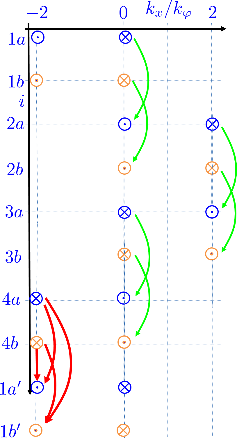
This is seen to require further tuning of the couplings [25]. However, due to the topological nature of the phase we describe, deviations from this specific form are possible, as long as the gap in the bulk does not close. In this case, a change in the couplings only affects the width of the edge modes.
Experimental realization
Our Q1D construction requires an alternating magnetic field. Experimentally, this can be realized using a snake-like wire, similar the one shown in Fig. 3a of the main text.
In this configuration, assuming that the width of the - regions is and using the Biot-Savart law we find that the desired current needed to create the states we constructed is of order
where is the one-dimensional density of the conducting band. Assuming , we get that currents of order should suffice.