Mechanically-Assisted Current-Induced Switching of the Magnetic Moment in a Torsional Oscillator
Abstract
Switching of the direction of the magnetic moment in a nanomagnet is studied within a modified Slonczewski’s model that permits torsional oscillations of the magnet. We show that the latter may inhibit or assist the magnetization switching, depending on parameters. Three regimes have been studied: the switching by torsional oscillations alone, the switching by the spin-polarized current with torsional oscillations permitted, and the magnetization switching by the current combined with the mechanical twist. We show that switching of the magnetic moment is possible in all three cases and that allowing torsional oscillations of the magnet may have certain advantages for applications. Phase diagrams are computed that show the range of parameters required for the switching.
pacs:
85.85.+j; 77.80.Fm; 75.78.JpI Introduction
The interest in spin dynamics operated by the electric current started with the suggestion Bergeretal to move domain walls in metals by the flow of spin-polarized electrons Parkin . The discovery of the interlayer exchange coupling and giant magnetoresistance in magnetic multilayers Fert ; Grunberg gave further boost to research on current-induced switching of magnetization. Slonczewski Slonczewski96 and Berger Berger96 demonstrated that a spin-polarized current could deliver a spin transfer torque that is sufficient to reorient the magnetic moment in a nanostructure. This suggestion triggered a wide-spread research on magnetic devices operated by spin-polarized currents Ralph . The field has progressed towards current-induced magnetization switching in the smallest nanostructures, including nanowires.
The question we are addressing in this paper is whether some degree of the mechanical freedom of the nanostructure would assist or inhibit the process of the magnetization switching. This question may be of particular importance because electric currents needed to switch the magnetization are rather high. Meanwhile, as is well known, the magnetization can be switched by the low amplitude high-frequency ac magnetic field. When absorbed in a resonant manner, it drives the magnetic moment up the energy barrier towards the reversal CGC-PRB2013 . The corresponding wavelengths of the electromagnetic field are typically in the centimeter range, making it difficult to selectively apply this method to small densely packed memory units. This prompted some researchers to use Josephson junctions for generation of the ac field in a small magnet Wern-SST2009 . The latter method, however, requires low temperatures.
Our work is motivated by the observation that, in the coordinate frame coupled to the magnetic anisotropy axes, the rotational vibrations of a magnet are equivalent to the ac magnetic field CGS-PRB2005 . Consequently, for nanomechanical resonators with vibrational frequencies comparable to the frequency of the ferromagnetic resonance, the effect of rotational vibrations can be similar to the effect of the ac magnetic field. Unlike the ac field, however, the mechanical vibrations can be localized at the nanoscale.
The connection between the magnetization reversal and mechanical rotation has been known for almost a century. It is manifested in the Barnett and Einstein - de Haas effects Barnett ; EdH . Coupling of mechanical resonators to classical magnetic moments has been studied in the past in the context of magnetization reversal in a thin magnetic film deposited on a microcantilever Kovalev-PRL2005 and nanomachines operated by the ac currents Stiles-JAP2002 ; Mohanty-PRB2004 ; Kovalev-PRB2007 . Einstein - de Haas effect in a magnetic microcantilever has been measured Wallis-APL2006 and explained JCG-PRB2009 by the motion of a domain wall. Various aspects of the electronic transport through magnetic molecules have been investigated together with the possibility of writing, storing, and reading spin information in memory devices based upon single-molecule magnets Timm-PRB2006 . Switching of the molecular spin by a spin-polarized current through a molecule bridged between conducting leads has been proposed Misiorny-PRB2007 and the effect of a soft vibrating mode of the molecule on the electronic transport has been studied Cornaglia-PRB2007 . Experiment has progressed to the measurement of the spin reversal in a single-molecule magnet drafted on a carbon nanotube Wern-NataureNano2013 ; Wern-ASC-Nano2013 .
In this paper, we extend the model of Slonczewski Slonczewski96 for a situation when the magnet subjected to a spin-polarized current is free to develop torsional oscillations. Our focus is on the magnetization reversal by the dc current, assisted by mechanical vibrations. Dynamics of the total angular momentum, spin plus mechanical angular momentum, makes this problem uniquely defined and free of any unknown coupling constants EC-Springer . The paper is structured as follows. The model is formulated in Section II. Mechanically assisted magnetization switching (MAMS) in the absence of the current is studied in Section III. Switching by the current in a system that permits torsional oscillations is investigated in Section IV. Section V deals with the magnetization switching assisted by both, the spin-polarized current and independently generated torsional oscillations. Results and possible implementations of the proposed mechanisms of magnetization switching are discussed in Section VI.
II Formulation of the Problem
In the original formulation of the problem by Slonczewski the magnetic moment of an uniaxial nanomagnet is switched by a spin-polarized current originating from a ferromagnet that has a fixed direction of the magnetization . The dynamics of is governed by the modified Landau-Lifshitz equation Lectures called the Slonczewski equationSlonczewski96 ; Ralph ,
| (1) |
Here is the magnitude of the uniaxial magnetic anisotropy field, and are unit vectors along and , and is the unit vector along the easy magnetization axis. Parameters , , , and are respectively the gyromagnetic ratio, the Gilbert damping, the Bohr magneton, and the electron charge. Function is given by Slonczewski96 where is the angle between and and is the spin polarization of the ferromagnetic material, .
Using spherical angles for the magnetic moment that undergoes the reversal, one can obtain from Eq. (1)
| (2) |
where is the absolute value of .
For complete switching one should require , which yields the Slonczewski condition, , for the magnetization reversal, with the critical current given by . Here is the frequency of the ferromagnetic resonance and is the numerical factor of order unity that depends on the spin polarization of the current. For iron while some materials may have close to one. If one writes then . For the numerical work we are choosing , which according to Eq. (2) corresponds to , , .
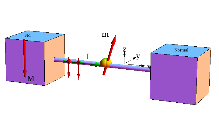
The geometry of our model (not the actual proportions) is depicted in Figure.1. It is conceptually similar to the Slonczewski’s model with the only difference that the nanomagnet is now a part of a torsional oscillator. Consequently, the direction of its easy magnetization axis is allowed oscillate in space in accordance with the coupled dynamics of the magnetic moment and the oscillator. The axis of the mechanical rotation is along the direction. When the torsional oscillator rotates by the angle about the axis, the direction of the easy axis in Eq. (1) transforms as were is the rotation matrix
| (3) |
We choose the direction of the magnetization of the ferromagnetic source of the spin polarized current, , to be along the direction and the equilibrium orientation of the easy axis of the nanomagnet to be along the direction. This gives
| (4) | |||
| (5) |
Substituting this into Eq. (1) and writing we obtain
| (6) | |||
| (7) | |||
where we switched to dimensionless
| (8) |
The above equations for must be accompanied by the equation of motion for the torsional oscillator. The latter follows from the equation where is the total angular momentum and is the torque. Their -components are given by
| (9) | |||
| (10) |
respectively, where is the moment of inertia of the rotator and is the frequency of its torsional vibrations. The first term in Eq. (9) is the spin angular momentum and the second term is the mechanical angular momentum. Similarly, the first term in Eq. (10) is the spin transfer torque from polarized electrons and the second term is the returning mechanical torque due to the elastic twist. Here we are assuming that the latter is proportional to the angle of twist . Note that, in, e.g., nanowires this assumption is justified even for large rotation angles Weinberger-Nano2009 . The negative sign of -terms is due to the fact that electron spin is opposite to the direction of the magnetization ( and are considered to be positive constants.). Introducing the dimensionless damping parameter of the torsional oscillator we obtain from
| (11) |
Here we use dimensionless parameters
| (12) |
Full dynamics of the system is described by equations (6), (7), and (11). Note that when , equations (6) and (7) reduce to Eq. (2).
III Magnetization Switching by Torsional Oscillations in the Absence of the Current
a
 b
b
 c
c
 d
d
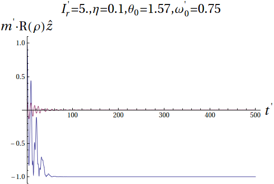
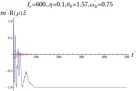
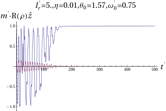
Numerical solution of equations (6), (7), and (11) at reveals that the magnetic moment can be switched by the vibrational motion of the torsional oscillator alone if the amplitude of the oscillations is sufficiently large. We call such a process the Mechanically-Assisted Magnetization Switching (MAMS). To initiate MAMS one twists the oscillator by a large angle, e.g., , waits until comes to thermal equilibrium by aligning with the new direction of the anisotropy axis , and then releases the oscillator. The initial condition is, therefore, . We find that MAMS is not very sensitive to the moment of inertia of the torsional oscillator but is sensitive to its resonance frequency, its damping constant, and the angle of twist, see Fig. 2. For every set of parameters the switching occurs in a certain range of the mechanical damping . It does not occur for very small or very large .
a
 b
b
a
 b
b
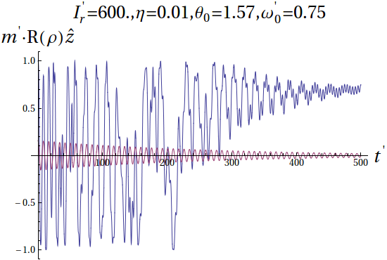
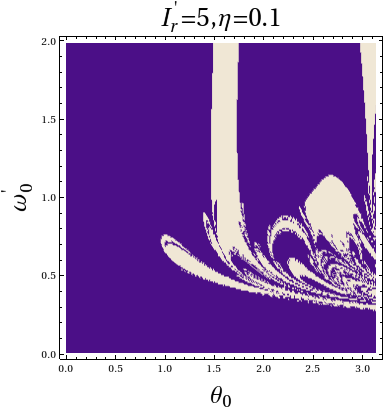
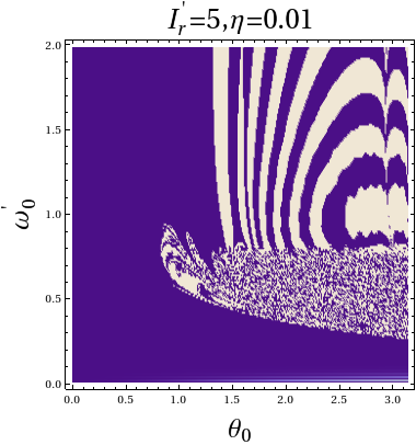
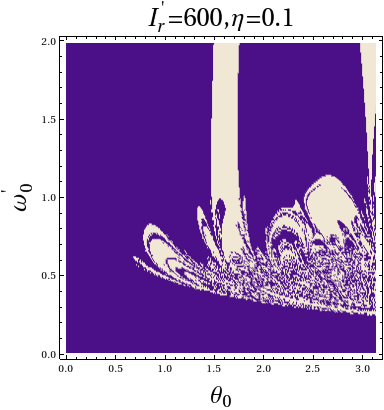
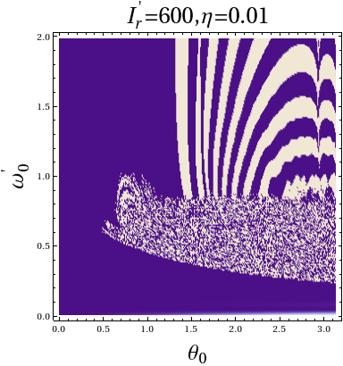
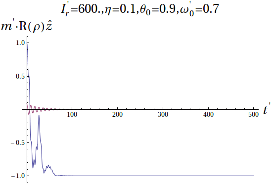
Switching phase diagrams of vs , for and , and , are shown in Figs. 3 and 4. Switching areas are depicted in light color. There are continuous areas of switching as well as areas of sporadic switching where the dynamics of the system is extremely sensitive to the parameters. It is interesting to notice that at a higher mechanical damping, , gives cleaner and faster switching than lower damping, . This is also clear from Fig. 2. To confirm and illustrate this observation we plot in Fig. 5 the dynamics corresponding to the point of in Fig. 4(a).
The initial angle of twist is rather large and one might look for alternative ways to induce MAMS. One such way is to let the angle of twist oscillate for a certain period of time (say, from to ). This corresponds to replacing the dynamics described by Eq. (11) with and then, at , letting Eq. (11) govern the rest of the damped motion. In this case, for each set of parameters, there is a window of for which the switching occurs and it is possible to induce the switching by smaller angles of twist, such as, e.g., and .
The above dynamics that includes driven oscillation followed by free oscillations produces well-defined areas as well as scattered areas of the switching in the phase diagram. For instance at , , the switching is possible at for and also near and . If the damping is reduced to 0.01, the windows of switching are and . At , the are two switching windows for and . One also finds narrow areas of switching near and . When the twist angle becomes very large (e.g. ) the values of for which switching occurs become scattered.
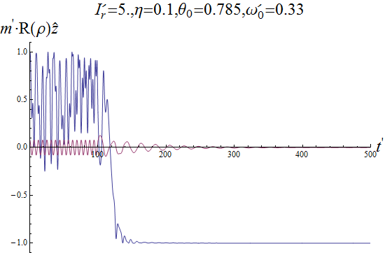
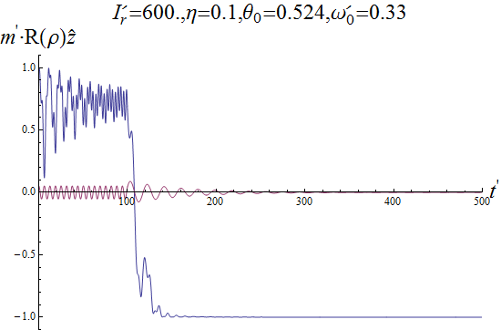
For a larger moment of inertia it is possible to induce switching by the driven oscillations followed by free oscillations for angles smaller than . For instance, if one can induce switching with in a narrow interval of resonance frequencies . This interval increases as increases but remains below for angles of twist less than . At the values of for which switching occurs are scattered between and . Time dependence of the mechanical twist and the magnetic moment for two different sets of parameters is shown in Fig. 6.
a
 b
b
IV Current-Induced Magnetization Switching in a Torsional Oscilator
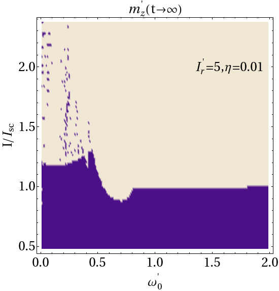
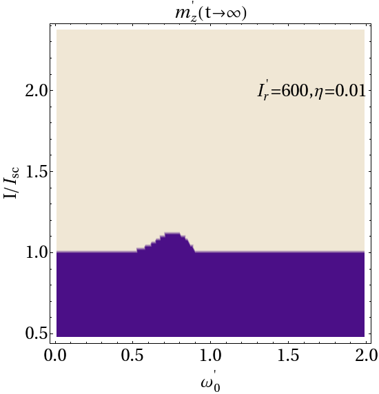
In this Section we solve numerically equations (6), (7), and (11) at a non-zero current assuming that mechanical oscillation are generated by the current itself and not by any external force as in the previous Section. As is known Ralph , to obtain a non-trivial dynajmics that leads to the magnetization reversal, one has to introduce small misalighnment of the equilibrium orientations of and , that we set at . Switching phase diagrams of vs , are shown in Fig. 7 for and at . Switching areas are depicted in light color. The areas of switching are continuous but with many small islands embedded, where the switching does not occur.
a
 b
b
In these plots the current required for the switching is compared with the Slonczewski’s critical current . Interestingly, for , that corresponds to a very small nanomagnet comparable to a magnetic molecule, the critical current is higher than if . However, above this value of there is a region where the critical current required for the switching is lower than the Slonczewski’s limit. At high resonance frequency of the oscillator the critical current coincides with the Slonczewski’s limit. For (as well as for higher moments of inertia studied) the critical current also coincides with the Slonczewski’s limit almost everywhere except for a narrow region of between and . Another interesting observation is the presence of sporadic non-switching islands down to the lowest values of in the phase diagram vs for a very light oscillator. This observation can be of practical importance for current-induced magnetization switching in the smallest nanomagnets because it implies that some degree of the mechanical freedom may cause instability of the process.
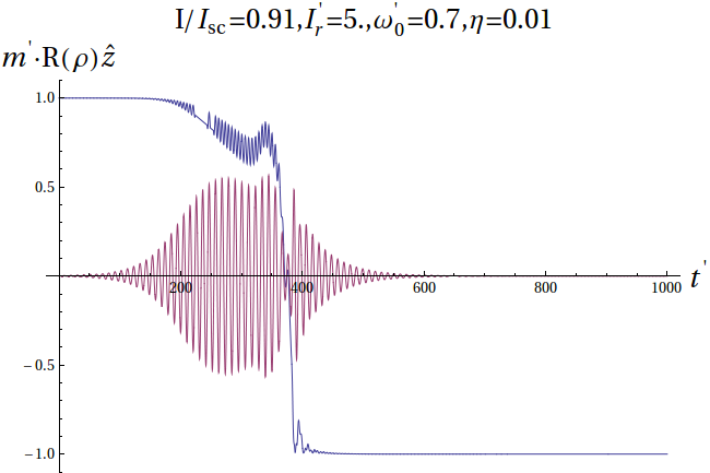
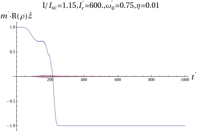
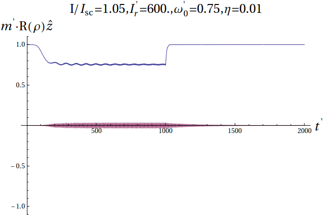
Three typical switching (non-switching) dynamics corresponding to particular points in the vs phase diagram are shown in Fig. 8.
a
 b
b
 c
c
Comparison of switching speeds shows mixed results. In general, the switching speed in a small nanomagnet is lower than that in a large nanomagnet except when the current is close to the critical current or lower. This observation may appear counterintuitive. However, analysis of the equations shows that it is related to the fact that a heavier resonator absorbs the change in the spin angular momentum faster.
V Switching by the Current Combined with a Mechanical Kick
a
 b
b
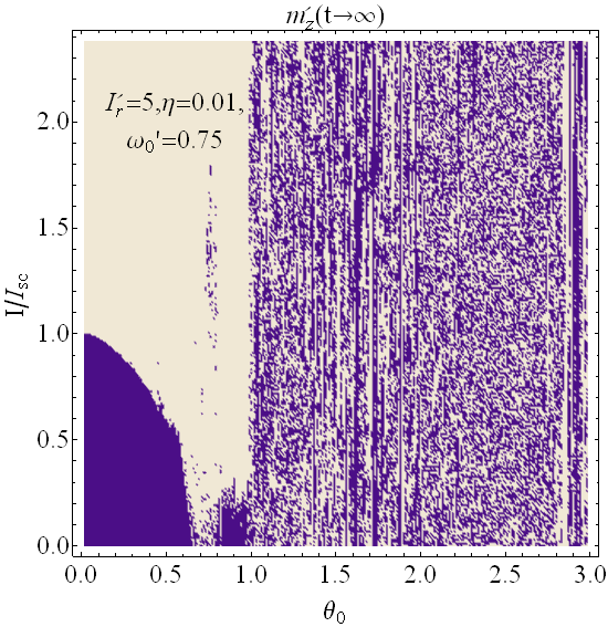
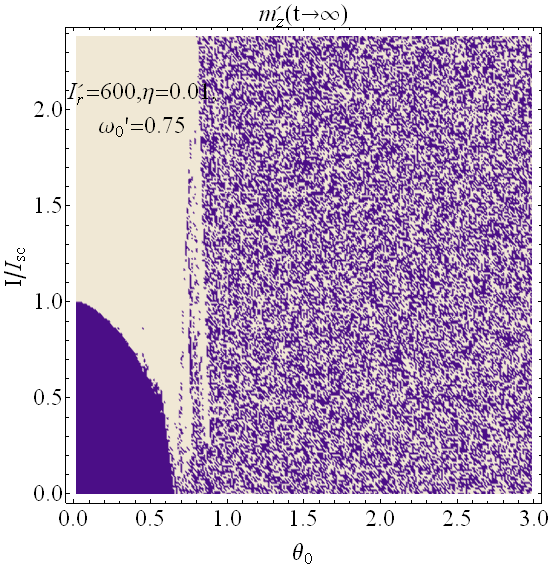
The analysis presented in the previous two Sections suggests that the maximum effect of the mechanical freedom of a nanomagnet may occur when the effect of the current is combined with a mechanical kick that twists the torsional oscillator by a significant angle. In this Section we solve equations (6), (7), and (11) at a non-zero current, assuming that is given by () from to and by Eq. (11) afterwards. Switching phase diagrams of vs for and at and are shown in Fig. 9. There are strong similarities between cases of light and heavy oscillators, suggesting that the effect is quite universal. In agreement with previous results the switching occurs at in the absence of the mechanical kick (). Also in agreement with the results of Section III the switching occurs in certain windows of even at . This observation may have practical importance because it shows the potential of MAMS for magnetization reversal by a lower spin-polarized current. As the moment of inertia increases, the width of the switching region shrinks. At high the switching becomes sporadic as a consequence of the chaotic dynamics with uncertain outcome for at .
VI Discussion
We have studied the effect of torsional oscillations of the magnet on the magnetization switching induced by the spin-polarized electric current. Our motivation for considering such a problem was two-fold. Firstly, applications of spin transfer torque require rather large currents. It is, therefore, natural to ask whether the process can be assisted by other means. Secondly, with various proposed designs of the magnetic memory operated by spin-polarized currents, it is not out of question that some magnetic elements would have a certain degree of mechanical freedom. The question we asked is whether mechanical vibrations inhibit or assist the magnetization reversal. Throughout the paper our focus has been on the mechanically assisted magnetization switching (MAMS) that can reduce the minimal required current as compared to the Slonczewski’s limit.
In Section III we have shown that a mechanical kick alone, supplied to the oscillator, can switch the magnetization. In this case the effect of the mechanical oscillations is equivalent to the effect of the ac field. Indeed, the spins in the rotating coordinate frame of the resonator oscillating at an angular velocity experience the effective ac magnetic field . Weak ac magnetic fields are known to be capable of switching the magnetization through consecuitive absorption of photons. They transfer the angular momentum to the macrospin of the nanomagnet and drive it up the anisotropy barrier until the reversal occurs CGC-PRB2013 . As we have seen in Section III, torsional oscillations of the resonator have a similar effect on the magnetic moment. The conditions required for the magnetization reversal are that the angle of twist is suffiiently large and that the resonance frequency of the mechanical oscillator is comparable to the frequency of the ferromagnetic resonance. The mechanical frequency of the torsional oscillator, , depends on two parameters, the torsion elastic modulus and the moment of inertia . The latter scales as the square of the oscillator size. Thus, the condition requires nanoscale oscillators. Nowadays GHz nanomechanical oscillators are common. Oscillation frequencies of hundreds of GHz have been reported in carbon nanotubes Island-NL2012 . Even at lower frequencies, however, one observation made in Section IV may be important for some of the existing devices that use spin-transfer torque to achieve the magnetization reversal. We have seen in the switching phase diagram that any degree of the mechanical freedom of the device may lead to its instability due to the chaotic coupled dynamics of the magnetic moment and the mechanical twist inside certain windows of the values of the parameters. This effect becomes progressively weaker, however, as the oscillator becomes heavier.
In the absence of the spin transfer torque delivered by the spin-polarized current, MAMS requires a large oscillation angle , which can be viewed as a trade-off for a large current needed without the mechanical assistance. The necessity of a large initial twist for the MAMS unassisted by the current is easy to understand by noticing that the effective ac magnetic field in the coordinate frame of the oscillator is proportional to the amplitude of the oscillations, . In Section V we have shown that combining the effect of the spins-polarized current with the effect of high-frequency mechanical oscillations one can reduce both, the critical current and the amplitude of the oscillations required for the switching. This observation suggests a memory-switching nanodevice that is operated by both, spin-polarized current and electromechanical actuation. A fast mechanical twist can be supplied to the oscillator through features used in the existing nanoelectromechanical systems (NEMS), by, e.g., placing it in the electric field and delivering a field pulse simultaneously with a pulse of the spin-polarized electric current. While this may be a challenging task at the nanoscale, the fast progress of nanotechnology leaves no doubt about its feasibility. The exact realization of the proposed combined switching mechanism may be far from the one schematically depicted in Fig. 1. However, the equations derived and solved in this paper are based upon general physical principles and they should apply to a variety of situations in which the dynamics of the magnetization is coupled with the mechanical rotational motion.
VII Acknowledgements
This work has been supported by the U.S. National Science Foundation through Grant No. DMR-1161571. Dr. Jaafar would like to acknowledge support from the PSC-CUNY Award, jointly funded by The Professional Staff Congress and The City University of New York. Numerical simulations carried under this research were supported, in part, under National Science Foundation Grants CNS-0958379 and CNS-0855217 and the City University of New York High Performance Computing Center at the College of Staten Island.
References
- (1) L. Berger, J. Phys. Chem. Solids 35, 947 (1974); C. Y. Hung and L. Berger, J. Appl. Phys. 63, 4276 (1988); E. Salhi and L. Berger, J. Appl. Phys. 76, 4787 (1994).
- (2) S. S. P. Parkin, M. Hayashi, and L. Thomas, Science 320, 190-194 (2008).
- (3) M. N. Baibich, J. M. Broto, A. Fert, F. Nguyen Van Dau, F. Petro, P. Etienne, G. Creuzet, A. Friederich, and J. Chazelas, Phys. Rev. Lett. 61, 2472 (1988).
- (4) G. Binasch, P. Grunberg, F. Saurenbach, and W. Zinn, Phys. Rev. B 39, 4828 (1989).
- (5) J. C. Slonczewski, J. Mag. Mag. Mat. 159, L1-L7 (1996).
- (6) L. Berger, Phys. Rev. B 54, 9353 (1996).
- (7) See, e.g., D. C. Ralph and M. D. Stiles, J. Mag. Mag. Mat. 320, 1190-1216 (2008) and references therein.
- (8) See, e.g., L. Cai, D. Garanin, and E. M. Chudnovsky, Phys. Rev. B 87, 024418 (2013), and references therein.
- (9) W. Wernsdorfer, Superconductor Science & Technology 22, 064013 (2009).
- (10) E. M. Chudnovsky, D. A. Garanin, and R. Schilling, Phys. Rev. B 72, 094426 (2005).
- (11) S. J. Barnett, Phys. Rev. 6, 239, 1915.
- (12) A. Einstein and W. J. de Haas, Verh. Dtsch. Phys. Ges. 17, 152, 1915; 18, 173, 1916; 18, 423, 1916.
- (13) A. A. Kovalev, G. E.W. Bauer, and A. Brataas, Phys. Rev. Lett. 94, 167201 (2005).
- (14) M. D. Stiles and A. Zangwill, J. Appl. Phys. 91, 6812 (2002).
- (15) P. Mohanty, G. Zolfagharkhani, S. Kettermann, and P. Fulde, Phys. Rev. B 70, 195301 (2004).
- (16) A. A. Kovalev, G. E.W. Bauer, and A. Brataas, Phys. Rev. B 75, 014430 (2007).
- (17) T. M. Wallis, J. Moreland, and P. Kabos, Appl. Phys. Lett. 89, 122502 (2006).
- (18) R. Jaafar, E. M. Chudnovsky, and D. A. Garanin, Phys. Rev. B 79, 104410 (2009).
- (19) C. Timm and F. Elste, Phys. Rev. B 73, 235304 (2006).
- (20) M. Misiorny and J. Barnaś, Phys. Rev. B 75, 134425 (2007); Phys. Rev. B 76, 054448 (2007).
- (21) P. S. Cornaglia, G. Usaj, and C. A. Balseiro, Phys. Rev. B 76, 241403(R) (2007).
- (22) M. Ganzhorn, S. Klyatskaya, M. Ruben, and W. Wernsdorfer, Nat. Nano. 8, 165 (2013).
- (23) M. Ganzhorn, S. Klyatskaya, M. Ruben, and W. Wernsdorfer. ACS Nano. 7, 6225 (2013).
- (24) E. M. Chudnovsky, Spin Tunneling in Magnetic Molecules That Have Full or Partial Mechanical Freedom (Chapter 3 in the book: Molecular Magnets – Physics and Applications, Ed. by J. Bartolomé, F. Luis., and J. F. Fernández, Springer, 2014)
- (25) E. M. Chudnovsky and J. Tejada, Lectures on Magnetism (Rinton Press, Princeton, New Jersey, 2006).
- (26) C. R. Weinberger and W. Cai, Nano Lett. 10, 139-142 (2010).
- (27) J. O. Island, V. Tayari, A. C. McRae, and A. R. Champagne, Nano. Lett. 12, 4564-4569 (2012).