Runge-Kutta Central Discontinuous Galerkin BGK Method for the Navier-Stokes Equations
Tan Ren111School of Aerospace Engineering, Beijing Institute of Technology, Beijing, 100081. E-mail: rentanx@gmail.com, Jun Hu222School of Aerospace Engineering, Beijing Institute of Technology, Beijing, 100081. E-mail: hujun@bit.edu.cn, Tao Xiong333Department of Mathematics, University of Houston, Houston, 77004. E-mail: txiong@math.uh.edu., Jing-Mei Qiu444Department of Mathematics, University of Houston, Houston, 77004. E-mail: jingqiu@math.uh.edu.
Abstract
In this paper, we propose a Runge-Kutta (RK) central discontinuous Galerkin (CDG) gas-kinetic BGK method for the Navier-Stokes equations. The proposed method is based on the CDG method defined on two sets of overlapping meshes to avoid discontinuous solutions at cell interfaces, as well as the gas-kinetic BGK model to evaluate fluxes for both convection and diffusion terms. Redundant representation of the numerical solution in the CDG method offers great convenience in the design of gas-kinetic BGK fluxes. Specifically, the evaluation of fluxes at cell interfaces of one set of computational mesh is right inside the cells of the staggered mesh, hence the corresponding particle distribution function for flux evaluation is much simpler than that in existing gas-kinetic BGK methods. As a central scheme, the proposed CDG-BGK has doubled the memory requirement as the corresponding DG scheme; on the other hand, for the convection part, the CFL time step constraint of the CDG method for numerical stability is relatively large compared with that for the DG method. Numerical boundary conditions have to be treated with special care. Numerical examples for 1D and 2D viscous flow simulations are presented to validate the accuracy and robustness of the proposed RK CDG-BGK method.
Keywords: Central discontinuous Galerkin method, gas-kinetic scheme, BGK model, Navier-Stokes equations, Computational fluid dynamics.
1 Introduction
There are two scales in describing compressible flow motions: the kinetic scale via the Boltzmann equation describing the particle distribution function and the hydrodynamic scale via the Euler or Navier-Stokes equations describing macroscopic flow variables such as mass, momentum and energy. In a gas-kinetic representation, all flow variables are moments of particle distribution function; the Euler or Navier-Stokes equations can be derived from taking moments of the Boltzmann equation based on the Chapman-Enskog expansion [3]. In this paper, we are interested in numerically simulating Navier-Stokes equations via the Boltzmann scheme with high order accuracy.
In the past few decades, many computational efforts have been devoted to simulate Euler or Navier-Stokes equations in the field of computational fluid dynamics (CFD). Many of classical numerical methods for Navier-Stokes equations involve solving convection and viscous terms separately on one set of computational grid. For the nonlinear convection term, the design of numerical fluxes at element interfaces is crucial to the success of numerical algorithms. Various approximate Riemann solvers have been proposed to approximate the wave structure of exact Riemann solutions, e.g. Godunov scheme [9], the approximate Riemann solvers due to Roe [30], Osher [29], Harten, Lax and van Leer [11], etc. For a summary on this topic, see [33]. For the viscous diffusion term, central difference method is often used. Another approach is to design fluxes at cell interfaces based on integrating particle distribution function in the phase space at kinetic scale. The kinetic flux vector splitting method for the Euler equations (KFVS-Euler) based on the collisionless Boltzmann equation is introduced in [25]. When viscous effect is considered, the particle distribution function contains both equilibrium (Maxwellian) and nonequilibrium parts of the gas flow; the inviscid and viscous terms can be treated simultaneously. For example, the kinetic flux vector splitting method for Navier-Stokes equations (KFVS-NS) was developed by introducing the nonequilibrium term in particle distribution obtained by Chapman-Enskog expansion in [4]; the gas-kinetic BGK method for Navier-Stokes equations (BGK-NS) was introduced in [40, 36].
To improve the performance of numerical schemes, high order schemes are introduced in 80’s and underwent great development since then. For example, in the finite volume or finite difference framework, there are the second order MUSCL scheme [34], the essentially non-oscillatory (ENO) scheme [10] and the weighted ENO (WENO) scheme [19, 12]. The discontinuous Galerkin (DG) method, as a class of finite element methods, has been very popular in the CFD community [7, 1, 8]. The high-order accuracy of DG is achieved by using high-order polynomial approximations within each element, where more than one degrees of freedom per element are stored and updated. The DG method has been well-known for its flexibility, h-p adaptivity, compactness and high parallel efficiency [5]. There have been many work in existing literatures in improving the BGK-NS method to be of high order accurate by interpolations or reconstructions such as WENO [24], by piecewise parabolic reconstruction of high order BGK fluxes [16], and by the DG framework [37, 18, 28]. These methods have been successfully applied in many engineering problems, such as the hypersonic viscous and heat conducting flows [15, 39, 17], 3D transonic flow [26], among many others. Comparisons between the schemes with approximate Riemann solvers and the particle distribution functions of the Boltzmann equation are provided in [24, 14].
The central scheme uses staggered meshes to avoid solving Riemann problems at cell interfaces and provides a black box solution to nonlinear hyperbolic conservation laws [27, 13]. Liu [20] introduced central schemes based on two sets of overlapping meshes. Taking advantages of the redundant representation of the solution on overlapping meshes, approximate Riemann solvers are not needed at cell interfaces, and the high order total variation diminishing (TVD) Runge-Kutta (RK) methods can be directly applied by the method of lines approach. Following similar spirit, central DG (CDG) methods are proposed and developed for hyperbolic equations in [21], and central local DG methods are proposed for diffusion equations in [23].
We propose to couple the CDG framework [21] with the BGK-NS method [36] for Navier-Stokes simulations. Compared with the DG BGK methods [37, 18, 28], CDG methods evolve two pieces of approximate solutions defined on two sets of overlapping meshes. Such redundant representation of numerical solution offers great convenience in the design of gas-kinetic BGK fluxes. Specifically, the evaluation of fluxes at cell interfaces of one set of computational mesh is right inside a cell of the staggered mesh (i.e. continuous regions of the solution at the staggered mesh). Hence, the particle distribution function, without involving two different Maxwellian distributions from the left and right states and the corresponding equilibrium state, is much simpler than existing gas-kinetic BGK methods [36, 37, 18, 28]. One of the key components that contributes to the success of the gas-kinetic BGK scheme [36] is the exact time evolution of the BGK equation along characteristics; such mechanism, despite its rather complicated formulation, brings the distribution function at cell interfaces to the equilibrium state in a very effective way. In the CDG framework, since the distribution function is continuous (at the interior of the other set of solution), such exact evolution is not as crucial. In our scheme, the method of lines approach is adopted; a third-order TVD RK method is used for temporal discretization. As the central scheme, the proposed CDG-BGK has doubled the memory requirement, since two sets of solutions have to be stored and updated simultaneously; on the other hand, for the convection part, the CFL time step constraint of the CDG method for numerical stability is relatively large compared with that for the DG method. The numerical boundary conditions have to be treated with special care. For example, a class of DG basis functions that preserves the given boundary condition, in the spirit of [6], are proposed for the wall boundary condition.
The paper is organized as follows. In Section 2, we propose the CDG-BGK method for one and two dimensional problems. The BGK fluxes, as well as numerical boundary conditions are discussed in details. In Section 3, following the pioneering work of [36, 18], extensive numerical results are demonstrated to showcase the effectiveness of the proposed approach. We conclude the paper in Section 4.
2 CDG-BGK method for compressible Navier-Stokes equations
In this section, we first introduce a 1D BGK model and the corresponding macroscopic conservative Navier-Stokes equations in Section 2.1. We propose to use the central discontinuous Galerkin (CDG) spatial discretization [20] coupled with a third-order total variation diminishing (TVD) Runge-Kutta (RK) temporal discretization [32] for solving the 1D Navier-Stokes equations in Section 2.2. The BGK type flux for both convection and viscous terms will be described in Section 2.3 and extension to two-dimensional cases will be presented in Section 2.4. Finally we discuss the numerical boundary conditions in Section 2.5.
2.1 The 1D BGK model and Navier-Stokes equations
The integro-differential kinetic Boltzmann equation is commonly used to describe the evolution of the particle distribution function. To avoid the complicated bilinear collisional operator of the Boltzmann equation, a simplified BGK model was proposed by Bhatnagar et al. [2]. The BGK collisional operator is known to preserve the collisional invariant properties of mass, momentum and energy, as well as the entropy dissipation property.
For a 1D flow, the BGK model can be written as [36]
| (2.1) |
where is the particle collision time, is an unknown function of space variable , time variable , particle velocity and internal variables . is taking into account to describe the internal motions, such as rotation and vibration [35]. is the Maxwellian distribution given by
| (2.2) |
where is the macroscopic density, is the macroscopic velocity in the direction, is related to the gas temperature by , with being the total number of degrees of freedom in .
The relation between the macroscopic conservative variables and the microscopic distribution function is
| (2.3) |
where is the total energy, with to be the pressure, and is the ratio of specific heats.
| (2.4) |
and is the volume element in the phase space with . The second equality in equation (2.3) is due to the fact that the BGK collisional term conserves mass, momentum and energy. In other words, and satisfy the conservation constraint
| (2.5) |
at any point in space and time. By taking moments of to the BGK model (2.1), due to equation (2.5), we get
| (2.6) |
or
| (2.7) |
where is the vector of the macroscopic conservative variables in equation (2.3). is the flux function from the kinetic formulation. Specifically,
| (2.8) |
where is the density flux, is the momentum flux, is the energy flux.
Based on the Chapman-Enskog expansion [3] with
| (2.9) |
from the BGK model (2.1), the compressible Navier-Stokes equations on macroscopic variables can be obtained by omitting terms (for details see [35])
| (2.10) |
where , are the viscous terms, is the dynamic viscousity coefficient. For a monatomic gas, , , the above Navier-Stokes equations become,
| (2.11) |
Remark 2.1.
The kinetic flux function in equation (2.8) encompasses both the convection and diffusion terms in the macroscopic Navier-Stokes system (2.10) with the approximation to the function by equation (2.9). The convection term in the Navier-Stokes system (2.10) is due to the contribution from the Maxwellian function in (2.9), while the diffusion term is due to the term in equation (2.9).
2.2 The RK CDG method
We propose to use the RK CDG method [21] to solve equation (2.7). The CDG method evolves two sets of approximate solutions defined on overlapping cells. Compared with the DG method, the CDG method does not need a numerical flux at the cell interface. The evaluation of the flux at the interface of one cell is right inside a cell of the other staggered cells. The CDG method uses the flux function of the solution at the staggered cells, which has no ambiguous values there. This is convenient for us to define the BGK flux in the next subsection. In the following, we first follow [21] to describe the CDG method.
We first consider a 1D domain with a partition of . Denote , and let and be two sets of overlapping cells. Two discrete spaces associated with the overlapping cells and are defined as
where the local space consists of polynomials of degree at most on .
The semi-discrete CDG method for solving (2.7) is given as follows: find two sets of approximate solutions and , such that for any , and for all ,
| (2.12) |
| (2.13) |
where are the right and left limits at the point . Here, the operations for vectors are in the component-wise sense [7]. is the maximum time step determined by the CFL condition, the specification of which can be found at the beginning of Section 3. The first terms on the right side of equations (2.12) and (2.13) are used to remove its dependency of numerical dissipation [21].
We focus our discussions on the approximate solution on cell . It can be expressed as
| (2.14) |
where is a basis function of . For example, the Legendre polynomials are a local orthogonal basis of . In the 1D case, , , ,, where . The approximate solution on cell can be defined similarly. The fluxes at the cell interfaces and the integrals on the right side of equations (2.12) and (2.13) are calculated by the gas-kinetic formulation presented in next section. The integrals on the right side of equation (2.12) contain solutions , which are continuous over two subintervals and . These integrals are computed by Gaussian quadrature rules on each of the subinterval. Similar comments apply for the integral on the right hand side of equation (2.13). If the solutions are discontinuous, the TVB limiter proposed by Cockburn and Shu [7] will be used to eliminate spurious oscillations and enforce the stability.
In this paper, we use a method of lines RK method for temporal discretization. Let , the third order TVD RK time discretization [31] for equations (2.12) and (2.13) is the following,
| (2.15) |
where is the current time step with and is the spatial operators on the right side of the semi-discrete equations (2.12) and (2.13).
2.3 The BGK flux
In this section, we describe how to evaluate the vector from the BGK model for the CDG method in equations (2.12)-(2.13). As pointed out in Remark 2.1, both convection and viscous terms in Navier-Stokes equations (2.10) comes from the vector , the evaluation of which mimics the Chapman-Enskog expansion [3]. Below, we provide a brief review of the existing algorithm in numerically approximating the BGK flux for the gas-kinetic scheme in the finite volume framework [36], with some of the ideas originally developed in [40, 35]. Further development of such schemes in the DG framework could be found in [37, 18, 28]. We note that it is very difficult to completely describe the BGK gas-kinetic scheme, hence we only outline main steps with intuition below, but refer readers to the original manuscript [36] for technical details.
Gas-kinetic scheme in finite volume framework [36]. The gas-kinetic BGK scheme updates the macroscopic conservative variables based on integrating equation (2.7) from to ,
| (2.16) |
where are cell averages of the macroscopic conservative variables, is current time step, and
| (2.17) |
Here is to be obtained from analytically solving the BGK model (2.1) via characteristically tracing with a source term. Specifically,
| (2.18) |
where is the particle trajectory, is the distribution function at , is the Maxwellian distribution function. Based on the framework outlined above, to update the macroscopic conservative variable , we need to specify procedures to approximate and in equation (2.18) and to evaluate the temporal integration in equation (2.17).
Approximation of . The initial distribution function is approximated based on equation (2.9) as well as a first order Taylor expansion in space around . We use superscripts and to indicate the left and right limits of the solutions respectively. In particular,
| (2.19) |
where
| (2.20) |
are the Maxwellian distribution functions based on macroscopic variables and at the left limit and the right limit respectively. are related to the spatial and temporal slopes of at the left limit , which are simply denoted as and with denoting the left limit. Similarly for , and . Specifically, for we have
| (2.21) |
which is a quadratic function of and . In terms of implementation, it was suggested in [36] to express in the following quadratic form of and
| (2.22) |
with the coefficients , , to be determined in a similar fashion as equations (2.28)-(2.31) below. can also be expressed in the form of
whose coefficients can be determined by the compatibility condition as in equations (2.33)-(2.34) below. Similar notations and comments apply to . More details can be found in [36].
Approximation of the equilibrium state . In order to get the Maxwellian function at in equation (2.18), let be approximated by the following function based on a Taylor expansion of the Maxwellian function around both in space and in time.
| (2.23) |
where is the Maxwellian distribution function at with
| (2.24) |
Here the macroscopic variables at the cell interface and time are obtained by
| (2.25) |
where are specified in equation (2.20). It can be observed that has discontinuous spatial slope and continuous temporal slope around : are related to the spatial slopes of from the left and right sides of and is the temporal slope of . They can be determined by a similar process as that for and . The only difference is that we use the ‘after-collision’ Maxwellian here, while we use the ‘before-collision’ equilibrium state and previously.
Analytical evaluation of the integration in equation (2.17). After is determined, we can get
where
Similarly for the integral. The details of the moments evaluation of such integration can be found in Appendix A of [36]. The temporal integration in equation (2.17) can also be performed analytically.
Proposed CDG-BGK method. We propose to use the CDG method for spatial discretization with the BGK flux for convection and diffusion terms in the Navier-Stokes system. In the CDG framework, two pieces of approximate solutions defined on overlapping cells are evolved. Since the cell interface on one set of cell is right inside a cell of the staggered cells, the solution at the staggered cell is continuous for flux evaluation without ambiguity, and we have
| (2.26) |
in equation (2.19). In other words, the before-collision and after-collision equilibrium states are the same. Due to this fact, the use of exact time evolution formula (2.18) is not as crucial. Therefore, we propose to use the third-order explicit TVD RK method for time evolution by the method of lines approach. Below we describe in details several numerical approximations needed for the proposed CDG-BGK method. They are, in some sense, special cases for the BGK scheme reviewed above.
Approximation of the distribution function . The particle distribution function at any spatial location and time is approximated by
| (2.27) |
where is the Maxwellian distribution (2.2) at time . Similar to equations (2.21) and (2.22), is related to the spatial slope of in the form of
| (2.28) |
The coefficients , and are determined by taking the spatial derivatives on the components of in equation (2.3),
| (2.29) |
where the slopes of the macroscopic conservative variables can be obtained by directly taking derivatives of the CDG polynomials. Equation (2.29) can be rewritten in a matrix-vector form as
| (2.30) |
where
| (2.31) |
with
is the temporal slope of with the following form,
| (2.32) |
where , , are uniquely determined by the compatibility condition
| (2.33) |
that is
| (2.34) |
where is the same as equation (2.31). The matrix is symmetric and can be efficiently inverted to determine the components of in equation (2.28) and in equation (2.32).
Integration in the phase space to obtain . After are determined, we can get the fluxes in equations (2.12) and (2.13) by taking the moments of to the distribution function given by equation (2.27),
| (2.35) |
The moments evaluation of the Maxwellian distribution function are provided in Appendix A.1.
Remark 2.3.
Although the derivation of the numerical flux functions comes from the kinetic BGK formulation, the integration in the phase space is done analytically as in Appendix A.1. The actual implementation is at the level of macroscopic variables. Hence, the computational cost is on the same scale of other existing Navier-Stokes solvers. The same comments apply to the gas-kinetic BGK scheme in [36].
Remark 2.4.
The BGK model corresponds to a unit Prandtl number . For a variable Prandtl number, we modify the energy flux by [36]
| (2.36) |
The heat flux can be evaluated precisely,
| (2.37) |
Remark 2.5.
In equation (2.29), the spatial derivative is directly taken on the CDG polynomials. It would lead to a order scheme with polynomial space for viscous flow simulations (not the optimal order). For convection dominated problems, the accuracy would still be order. Such fact is verified in our numerical results in Section 3.
2.4 Extension to two-dimensional cases
In this subsection, we extend the proposed CDG-BGK method in previous subsections to two-dimensional cases. The 2D BGK model can be written as
| (2.38) |
where is the particle distribution function of space variables , time variable , particle velocities and internal variables . While is the Maxwellian distribution given by
| (2.39) |
where is the macroscopic density, , are the macroscopic velocities in directions, with being the total number of degrees of freedom in . Based on the conservative constraint condition (2.5), taking the moments of to equation (2.38), we can get the following system of macroscopic conservative equation
| (2.40) |
or
| (2.41) |
Here is the vector of macroscopic conservative variables, and are the flux functions in directions respectively. The Chapman-Enskog expansion with , and from equation (2.40) gives a 2D compressible Navier-Stokes equations [35],
| (2.42) |
where
The total energy with the pressure and . For monatomic gas and , while for diatomic gas and . Similarly, the kinetic flux functions in equation (2.41) are represented by both convection and diffusion terms in the 2D macroscopic Navier-Stokes equations (2.42) in directions respectively.
We consider the following numerical discretization of a 2D rectangular domain . Let and be partitions of and respectively, with , . Let , , , . Denote and be two sets of overlapping meshes for , with and , see Fig. 2.1. Two discrete spaces associated with the overlapping cells and are defined as
where the local space consists of polynomials of degree at most on .
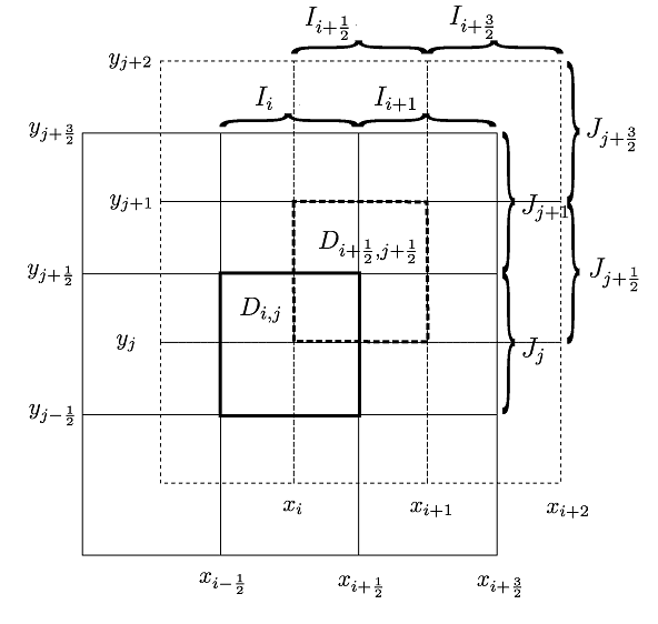
Similar to the 1D case, the semi-discrete CDG scheme for solving equation (2.41) is given as follows: find two sets of approximate solutions and , such that for any , and for all and ,
| (2.43) |
| (2.44) |
Here vectors operations are component-wise operations. The semi-discrete scheme of equations (2.43)-(2.44) will be evolved in time by the third-order TVD RK time method (2.15). The approximate solution on the element can be expressed as
| (2.45) |
The 2D Legendre polynomials are taken as a local orthogonal basis on ,
where , . The approximate solution can be obtained similarly. The fluxes and on the right side of equations (2.43) and (2.44) are calculated by the gas-kinetic formulation presented below. Note that in 2D case, the first two integrals on the right side of equation (2.43) contain four pieces of solutions on four subcells, each of which is calculated by a 2D Gaussian quadrature rule. The rest two integrals on the right side of equation (2.43) are associated with two pieces of solutions, each of which is determined by a 1D Gaussian quadrature rule. Similar comments apply for the integrals on the right side of equation (2.44).
In the following, we follow the spirit of 1D BGK scheme to propose the 2D strategy for computing the fluxes and . The distribution function in equation (2.38) can be expressed as
| (2.46) |
up to the first order of , where is the Maxwellian distribution function (2.39) associated with the macroscopic variables at on the dual mesh. Similar to the 1D case, are related to the spatial slopes of in directions respectively, and are taken to be in the form of
The components of and can be uniquely determined from the partial derivatives of the macroscopic conservative variables with respect to
| (2.47) |
The above equations can be written in a matrix-vector form as
| (2.48) |
where
| (2.49) |
with
Thus, can be obtained by solving the linear system (2.48). Similar procedures can be used to get . is related to the temporal slope of with the following form
where , , , are uniquely determined by the compatibility condition
After and are determined, , , , can be obtained by solving the following linear system
| (2.50) |
with specified in equation (2.49).
2.5 Numerical boundary conditions
For the numerical tests in this paper, we follow closely the examples in [36, 18], with similar boundary conditions, e.g. inflow, outflow and wall boundary conditions. In the CDG method, two sets of approximate solutions on overlapping cells are updated; thus numerical boundary conditions are needed for both solutions. The inflow and outflow conditions can be treated, in a similar manner as those in DG, for both solutions in the CDG method. The more challenging case is the wall boundary conditions.
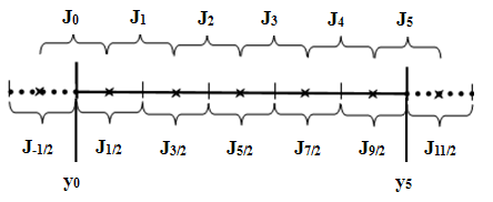
In the following, we take the Couette flow in a channel with the bottom wall fixed and the top wall moving (see Section 3.2) as an example to describe the proposed numerical no-slip boundary condition at both walls. Although the Couette flow is a 2D problem, it can be implemented as a 1D problem since the solutions do not depend on . We assume the overlapping cells in the -direction as plotted in Fig. 2.2 with the walls located at and with , . Cells and are cut through by the walls. For the no-slip boundary condition at wall, the physical macroscopic velocities are zero on the wall. However, the numerical ones might not be zero due to numerical errors; such non-zero errors might accumulated during long time evolution and eventually impact the effectiveness of the proposed scheme. We propose to enforce zero velocities at the numerical level. For example, in cell at the bottom wall, we adopt the following basis functions
with
where , are the coefficients of for the basis with , similarly for . Since at , we only need to enforce to get . Similarly for another set of solutions in cell . The approximate solution in the ghost cell is obtained in a mirror-symmetric manner with respect to the solution on cell . Similar ideas of using a special set of basis to preserve the solution structure in DG methods can also be found in [6]. Boundary conditions on the top wall can be set similarly.
3 Numerical examples
In this section, we present simulation results of the proposed CDG-BGK method for several 1D and 2D viscous flow problems. For comparison, most of the examples are taken from [36, 18]. The maximum time step in equations. (2.12), (2.13), (2.43) and (2.44) is chosen based on the CFL condition, while the time step in evolution is taken to be unless otherwise specified.
We define, in 1D cases,
and in 2D cases,
where and , with and , similarly for and . are the maximum eigenvalues in and directions respectively. The eigenvalues are in the direction and in the direction for convection part, where is the speed of sound. and are the CFL numbers for the convection and diffusion parts. In our numerical examples, for the third-order TVD Runge-Kutta method (2.15), we take [22] and for , and solution spaces respectively. Our numbers are larger than those taken in [23] for the central local DG method, yet they are working properly for all our numerical examples. The Prandtl number modification (2.36) will be used in all numerical examples except the laminar boundary layer case.
3.1 Accuracy test
We first solve the Navier-Stokes equations (2.7) with smooth solutions, where the initial conditions are given by
| (3.1) |
The computational domain is with periodic boundary condition. Two different viscosity coefficients are tested, and , corresponding to a convection-dominated flow and a viscous flow, respectively. For this example, the Prandtl number is and the ratio of specific heats is . We compute the solutions up to time . TVB limiter is not used for this case. Since the exact solution is not available for this problem, the numerical errors and orders of density are computed by comparing to the reference solution which is obtained by the solution space with 1280 cells. Here we take for the case so that the temporal error is not dominated. The results are shown in Table 3.1. -order convergent rate can be observed for the proposed CDG-BGK scheme with and solution spaces, while -order convergent rate for even and -order convergent rate for odd can be observed for the solution with and solution spaces.
| N | error | order | error | order | |
|---|---|---|---|---|---|
| 10 | 0.21E-02 | – | 0.34E-02 | – | |
| 20 | 0.78E-03 | 1.45 | 0.12E-02 | 1.50 | |
| 40 | 0.24E-03 | 1.72 | 0.36E-03 | 1.70 | |
| 80 | 0.65E-04 | 1.88 | 0.10E-03 | 1.86 | |
| 160 | 0.17E-04 | 1.94 | 0.26E-04 | 1.93 | |
| 10 | 0.28E-03 | – | 0.46E-03 | – | |
| 20 | 0.36E-04 | 2.94 | 0.58E-04 | 2.98 | |
| 40 | 0.46E-05 | 2.98 | 0.73E-05 | 3.00 | |
| 80 | 0.58E-06 | 2.99 | 0.92E-06 | 3.00 | |
| 160 | 0.73E-07 | 2.99 | 0.12E-06 | 2.99 | |
| 10 | 0.27E-04 | – | 0.38E-04 | – | |
| 20 | 0.16E-05 | 4.04 | 0.25E-05 | 3.95 | |
| 40 | 0.10E-06 | 4.02 | 0.15E-06 | 3.99 | |
| 80 | 0.63E-08 | 4.01 | 0.97E-08 | 3.99 | |
| 160 | 0.39E-09 | 4.00 | 0.61E-09 | 3.99 | |
| 10 | 0.10E-02 | – | 0.19E-02 | – | |
| 20 | 0.27E-03 | 1.93 | 0.52E-03 | 1.89 | |
| 40 | 0.68E-04 | 1.98 | 0.13E-03 | 1.97 | |
| 80 | 0.17E-04 | 2.00 | 0.33E-04 | 1.99 | |
| 160 | 0.42E-05 | 2.02 | 0.84E-05 | 2.00 | |
| 10 | 0.13E-03 | – | 0.22E-03 | – | |
| 20 | 0.35E-04 | 1.95 | 0.56E-04 | 1.94 | |
| 40 | 0.87E-05 | 1.99 | 0.14E-04 | 1.99 | |
| 80 | 0.22E-05 | 2.00 | 0.35E-05 | 2.00 | |
| 160 | 0.55E-06 | 2.00 | 0.89E-06 | 2.00 | |
| 10 | 0.93E-05 | – | 0.17E-04 | – | |
| 20 | 0.74E-06 | 3.65 | 0.14E-05 | 3.61 | |
| 40 | 0.49E-07 | 3.92 | 0.90E-07 | 3.93 | |
| 80 | 0.31E-08 | 3.99 | 0.56E-08 | 4.02 | |
| 160 | 0.19E-09 | 4.03 | 0.38E-09 | 3.89 |
3.2 Couette flow
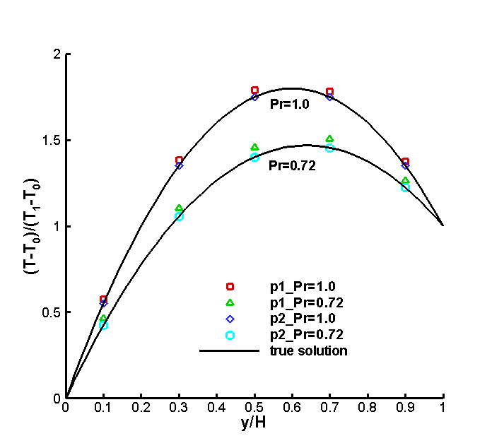
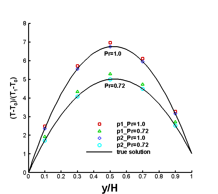
In the second example, we consider the couette flow in a channel of height , with the bottom wall fixed and the top wall moving at a constant speed in the horizontal direction. We assume isothermal boundary condition at the bottom and top walls with temperature being and respectively. If the viscosity and heat conduction coefficients and are constant, an analytical solution for the steady state temperature distribution can be obtained, that is
| (3.2) |
where the Eckert number is . is the heat capacity at a constant pressure, for a monatomic gas and for a diatomic gas .
The solution of this problem does not depend on , hence we solve it as a reduced 1D problem from equation (2.41) in the direction, that is,
i.e. the compressible Navier-Stokes equations (2.42) without the -derivative term.
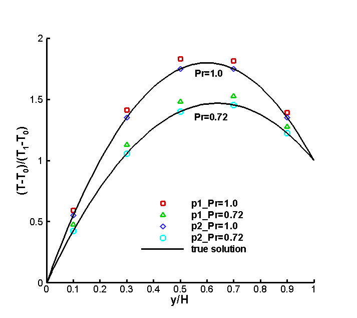
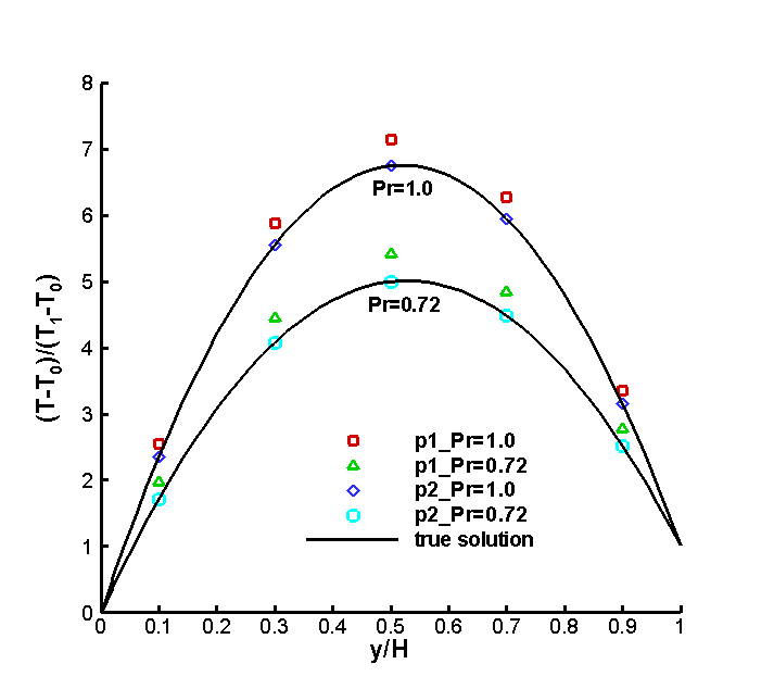
We take the computational domain to be () and divided by cells with cell size . The isothermal no-slip boundary condition with pressure gradient being zero in direction is used on the bottom and top walls [36]. Here we consider the temperature and at the boundaries with different ratios of specific heats , different Prandtl numbers and different Eckert numbers . For specific settings, see Table 3.2. We take and . The initial conditions are
where is the Mach number.
| 0.72,1.0 | 5/3 | 10 | 1/1.19960 | 1/1.20040 |
| 0.72,1.0 | 5/3 | 50 | 1/1.19992 | 1/1.20008 |
| 0.72,1.0 | 7/5 | 10 | 1/1.42851 | 1/1.42863 |
| 0.72,1.0 | 7/5 | 50 | 1/1.42829 | 1/1.42886 |
The results with different boundary settings are shown in Figs. 3.1 and 3.2. The Prandtl number modification (2.36) is used in cases. From the figures, we can see that: (1) numerical results match the analytical solutions very well with different parameters even on such a coarse numerical cell; (2) the implementation of the Prandtl number modification is needed compared with the analytical solutions and (3) solution space gives more accurate results than solution space with the same cell size. Numerical errors and orders of convergence to analytical solutions are summarized in Table 3.3. Roughly order convergent rate is observed for the method with polynomial space.
| N | error | order | error | order | |
|---|---|---|---|---|---|
| 5 | 0.61E+00 | – | 0.66E+00 | – | |
| 10 | 0.19E+00 | 1.66 | 0.22E+00 | 1.60 | |
| 20 | 0.61E-01 | 1.65 | 0.74E-01 | 1.55 | |
| 5 | 0.13E-03 | – | 0.16E-03 | – | |
| 10 | 0.30E-04 | 2.14 | 0.41E-04 | 1.96 | |
| 20 | 0.74E-05 | 2.04 | 0.11E-04 | 1.96 | |
| 5 | 0.22E-04 | – | 0.28E-04 | – | |
| 10 | 0.35E-05 | 2.63 | 0.45E-05 | 2.62 | |
| 20 | 0.61E-06 | 2.51 | 0.82E-06 | 2.46 |
3.3 Navier-Stokes shock structure
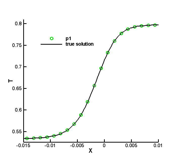
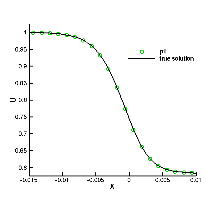
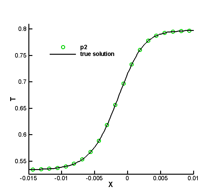
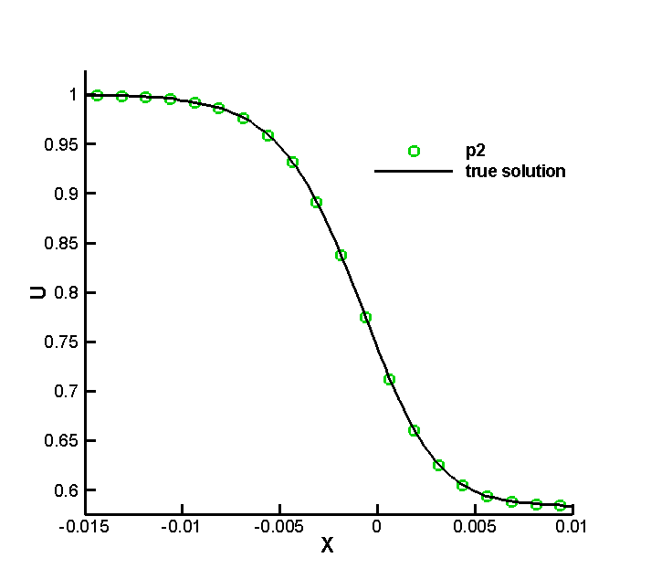
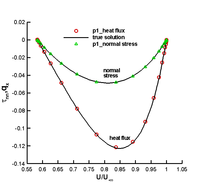
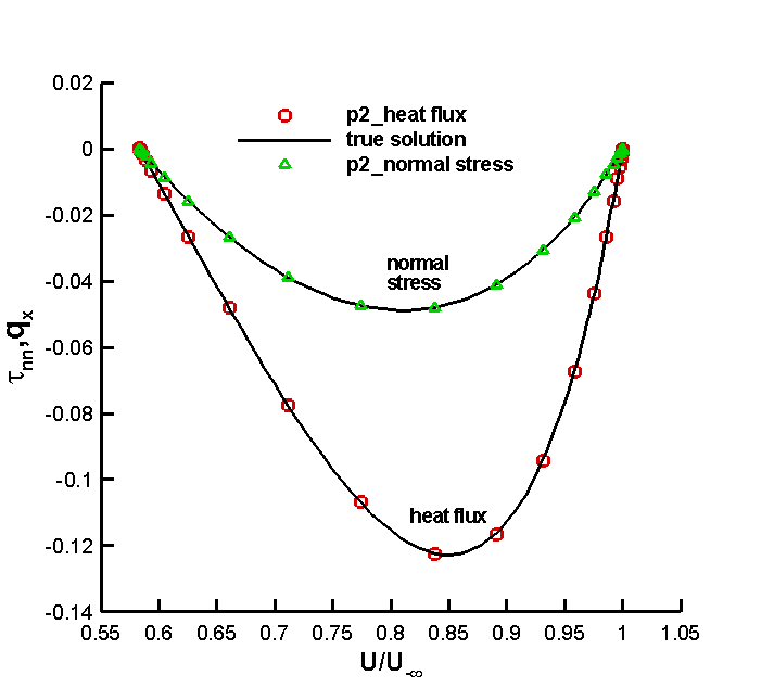
Now we consider the shock structure problem for a monatomic gas by solving the Navier-Stokes equations (2.7). and the dynamical viscosity coefficient is , and denote the values at the upstream and downsteam respectively. The dynamical viscosity coefficient at the upstream keeps to be a constant . The collision time in the BGK model is local via the relationship in each cell. The Mach number at the upstream and the Prandtl number . The initial conditions are
For this problem, the shock would not arrive at the left or right boundary. Hence, we can impose the boundary condition as the constant left and right states. The reference solution can be obtained by integrating the steady state Navier-Stokes equations, with the corresponding Matlab programs available in Appendix C of [36].
The computational domain is and the cell size for both and cases. TVB limiter is used for this example. The results are presented in Fig. 3.3. In the figures, the normal stress and the heat flux are defined to be
From these results, we can see that the shock structure is captured well with a reasonable number of grid points. The difference between the results from and cases are very small.
3.4 Shock tube problem
In the fourth example, the Sod problem is tested by solving the Navier-Stokes equations (2.7) with and . The computational domain is with the cell size , and in this case. TVB limiter is used for this example. The initial conditions are
| (3.3) |
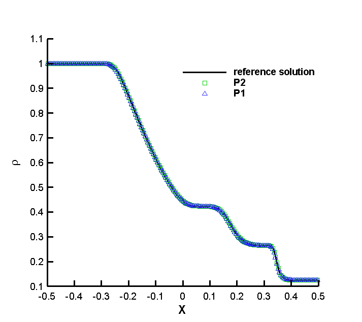
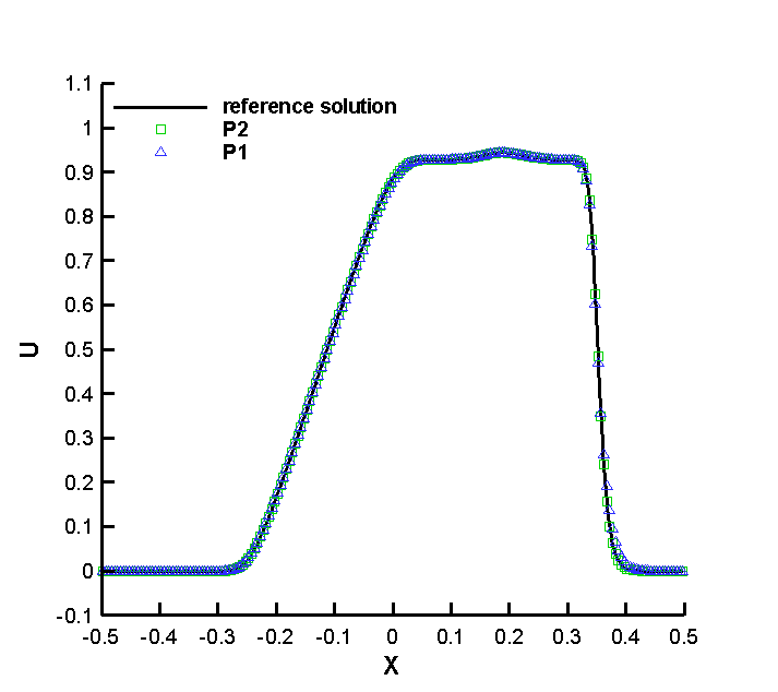
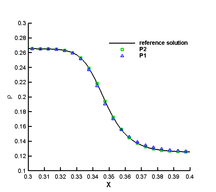
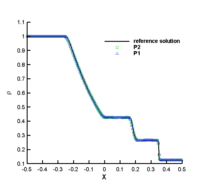
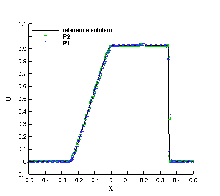
We compute the solutions up to time . Similar to shock structure case, we can impose the boundary condition as the constant left and right states. In Fig. 3.4, we show the results with a kinematic viscosity coefficient . The solid lines are the reference solutions computed on a much refined cell size with solution space. Both the shock and the contact discontinuity are captured well. From the zoom-in Fig. 3.5, we can see the case gives slightly better results than the case. The results with a smaller viscosity coefficient are presented in Fig. 3.6. The CDG-BGK method can capture the sharp discontinuity.
3.5 Laminar boundary layer
The last example is the 2D laminar boundary layer problem over a flat plate and we solve the 2D Navier-Stokes equations (2.41). The wall starts from with a length of at . A uniform rectangular mesh with cells is used on the computational domain . The initial conditions are set to be
We take , , and . The kinematic viscosity coefficient is . The Reynolds number based on the upstream flow states and the length is . No limiter is used in this case. The no-slip adiabatic boundary condition is imposed on the flat plate. Mirror-symmetric boundary condition is used for the other part of the bottom boundary. On the left and top boundaries, the non-reflective boundary condition is used, which is based on the Riemann invariants. For example, on the left boundary, let be the macroscopic density, velocity and pressure right inside the computation domain adjacent to the left boundary and be the values on the ghost cell correspondingly, we have
| (3.4) |
where and are two Riemann invariants, is the entropy from the initial condition, and are speeds of sound. in (3.4) are obtained from the conditions , and . For details, see [38]. Similar treatments on the top boundary. A first order extrapolation of cell average of the conservative variables is used at the right boundary.
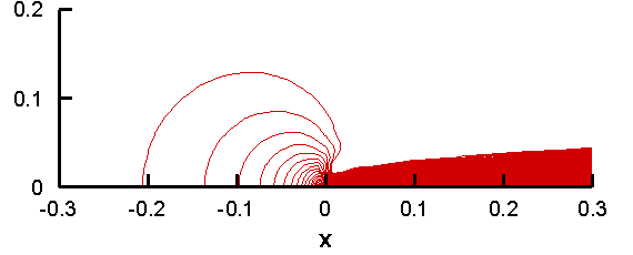
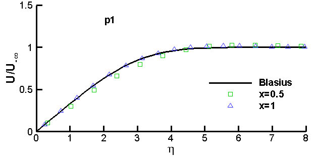
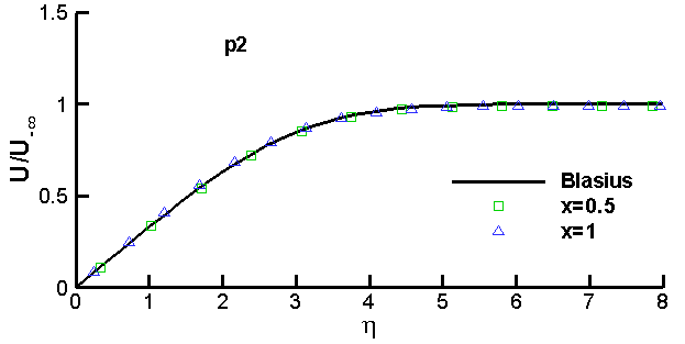
In Fig. 3.7, we show the solution of the velocity in the direction. The non-dimensional velocity at location and for both and cases are shown in Fig. 3.8, which are compared to the Blasius solution. In the plots, , and we can see that the scheme with the solution space performs slightly better than that with the solution space.

4 Conclusion
In this paper, a novel CDG-BGK method for viscous flow simulations is proposed. The new scheme inherits several merits from both the CDG framework and the gas-kinetic BGK schemes. The fluxes in the BGK method is based on the particle transport and collisional mechanism via the gas-kinetic BGK model. Such fluxes take into account of both the convective and viscous terms, due to the intrinsic connection between the gas-kinetic BGK model and the Navier-Stokes equations. The CDG method evolves two pieces of approximate solutions defined on overlapping meshes. The cell interfaces of one computational mesh are inside the staggered mesh, hence the fluxes are in the continuous region of the staggered solution. For the CDG-BGK method, the distribution function in the interior of elements is continuous and is much easier to evaluate than existing finite volume or DG BGK methods. Numerical results in 1D and 2D illustrate the accuracy and robustness of the proposed CDG-BGK scheme.
Acknowledgement. Research of the first author is partly supported by the scholarship from China Scholarship Council (CSC) under the Grant CSC No. 201206030032. The first, third and fourth authors are partially supported by Air Force Office of Scientific Computing YIP grant FA9550-12-0318, NSF grant DMS-1217008 and University of Houston. The authors would like to thank F.-Y. Li, H.-W. Liu and C.-W. Shu for helpful discussions about boundary conditions.
Appendix A Appendix
A.1 1D and 2D moments
The evaluation of the Maxwellian is given in this section, the details can be found in [36]. For the 1D flow, the moments of Maxwellian with respect to is introduced as,
and the general moment formula is
where is integer, and is an even integer. The moments of are
| (A.1) |
and
| (A.2) |
For the 2D flow,
and the general moment formula is
where are integers, and is an even integer. Here the moments and are the same as the 1D flow. The moments of are
| (A.3) |
References
- [1] F. Bassi and S. Rebay, A high-order accurate discontinuous finite element method for the numerical solution of the compressible Navier–Stokes equations, Journal of Computational Physics, 131 (1997), pp. 267–279.
- [2] P. L. Bhatnagar, E. P. Gross, and M. Krook, A model for collision processes in gases. I. Small amplitude processes in charged and neutral one-component systems, Physical Review, 94 (1954), pp. 511–525.
- [3] S. Chapman and T. G. Cowling, The mathematical theory of non-uniform gases: an account of the kinetic theory of viscosity, thermal conduction and diffusion in gases, Cambridge University Press, 1991.
- [4] S.-Y. Chou and D. Baganoff, Kinetic flux–vector splitting for the Navier–Stokes equations, Journal of Computational Physics, 130 (1997), pp. 217–230.
- [5] B. Cockburn, G. E. Karniadakis, and C.-W. Shu, The development of discontinuous Galerkin methods, Springer, 2000.
- [6] B. Cockburn, F. Li, and C.-W. Shu, Locally divergence-free discontinuous Galerkin methods for the Maxwell equations, Journal of Computational Physics, 194 (2004), pp. 588–610.
- [7] B. Cockburn, S.-Y. Lin, and C.-W. Shu, TVB Runge-Kutta local projection discontinuous Galerkin finite element method for conservation laws III: one-dimensional systems, Journal of Computational Physics, 84 (1989), pp. 90–113.
- [8] B. Cockburn and C.-W. Shu, Runge–Kutta discontinuous Galerkin methods for convection-dominated problems, Journal of Scientific Computing, 16 (2001), pp. 173–261.
- [9] S. Godunov, A finite difference scheme for numerical computation of the discontinuous wave solutions of equations of fluid dynamics, Math. Sb., 47 (1959), pp. 271–306.
- [10] A. Harten, B. Engquist, S. Osher, and S. R. Chakravarthy, Uniformly high order accurate essentially non-oscillatory schemes, III, Journal of Computational Physics, 71 (1987), pp. 231–303.
- [11] A. Harten, P. D. Lax, and B. v. Leer, On upstream differencing and Godunov-type schemes for hyperbolic conservation laws, SIAM review, 25 (1983), pp. 35–61.
- [12] G.-S. Jiang and C.-W. Shu, Efficient Implementation of Weighted ENO Schemes, Journal of Computational Physics, 126 (1996), pp. 202–228.
- [13] A. Kurganov and E. Tadmor, New high-resolution central schemes for nonlinear conservation laws and convection–diffusion equations, Journal of Computational Physics, 160 (2000), pp. 241–282.
- [14] J. Li, Q. Li, and K. Xu, Comparison of the generalized Riemann solver and the gas-kinetic scheme for inviscid compressible flow simulations, Journal of Computational Physics, 230 (2011), pp. 5080–5099.
- [15] Q. Li, S. Fu, and K. Xu, Application of gas-kinetic scheme with kinetic boundary conditions in hypersonic flow, AIAA Journal, 43 (2005), pp. 2170–2176.
- [16] Q. Li, K. Xu, and S. Fu, A high-order gas-kinetic Navier–Stokes flow solver, Journal of Computational Physics, 229 (2010), pp. 6715–6731.
- [17] W. Liao, L.-S. Luo, and K. Xu, Gas-kinetic scheme for continuum and near-continuum hypersonic flows, Journal of Spacecraft and Rockets, 44 (2007), pp. 1232–1240.
- [18] H. Liu and K. Xu, A Runge–Kutta discontinuous Galerkin method for viscous flow equations, Journal of Computational Physics, 224 (2007), pp. 1223–1242.
- [19] X.-D. Liu, S. Osher, and T. Chan, Weighted essentially non-oscillatory schemes, Journal of Computational Physics, 115 (1994), pp. 200–212.
- [20] Y. Liu, Central schemes on overlapping cells, Journal of Computational Physics, 209 (2005), pp. 82–104.
- [21] Y. Liu, C.-W. Shu, E. Tadmor, and M. Zhang, Central discontinuous Galerkin methods on overlapping cells with a nonoscillatory hierarchical reconstruction, SIAM Journal on Numerical Analysis, 45 (2007), pp. 2442–2467.
- [22] , L2 stability analysis of the central discontinuous Galerkin method and a comparison between the central and regular discontinuous Galerkin methods, ESAIM: Mathematical Modelling and Numerical Analysis, 42 (2008), pp. 593–607.
- [23] , Central local discontinuous Galerkin methods on overlapping cells for diffusion equations, ESAIM-Mathematical Modelling and NumericalAnalysis, 45 (2011), pp. 1009–1032.
- [24] J. Luo, L. Xuan, and K. Xu, Comparison of Fifth-Order WENO Scheme and Finite Volume WENO-Gas-Kinetic Scheme for Inviscid and Viscous Flow Simulation, Communications in Computational Physics, 14 (2013), pp. 599–620.
- [25] J. Mandal and S. Deshpande, Kinetic flux vector splitting for Euler equations, Computers & Fluids, 23 (1994), pp. 447–478.
- [26] G. May, B. Srinivasan, and A. Jameson, An improved gas-kinetic BGK finite-volume method for three-dimensional transonic flow, Journal of Computational Physics, 220 (2007), pp. 856–878.
- [27] H. Nessyahu and E. Tadmor, Non-oscillatory central differencing for hyperbolic conservation laws, Journal of Computational Physics, 87 (1990), pp. 408–463.
- [28] G. Ni, S. Jiang, and K. Xu, A DGBGK scheme based on WENO limiters for viscous and inviscid flows, Journal of Computational Physics, 227 (2008), pp. 5799–5815.
- [29] S. Osher and F. Solomon, Upwind difference schemes for hyperbolic systems of conservation laws, Mathematics of computation, 38 (1982), pp. 339–374.
- [30] P. L. Roe, Approximate Riemann solvers, parameter vectors, and difference schemes, Journal of Computational Physics, 43 (1981), pp. 357–372.
- [31] C.-W. Shu, Total-variation-diminishing time discretizations, SIAM Journal on Scientific and Statistical Computing, 9 (1988), pp. 1073–1084.
- [32] C.-W. Shu and S. Osher, Efficient implementation of essentially non-oscillatory shock-capturing schemes, Journal of Computational Physics, 77 (1988), pp. 439–471.
- [33] E. F. Toro, Riemann solvers and numerical methods for fluid dynamics: a practical introduction, Springer, 2009.
- [34] B. Van Leer, Towards the ultimate conservative difference scheme. V. A second-order sequel to Godunov’s method, Journal of Computational Physics, 32 (1979), pp. 101–136.
- [35] K. Xu, Gas-kinetic schemes for unsteady compressible flow simulations, Lecture series-van Kareman Institute for fluid dynamics, 3 (1998), pp. C1–C202.
- [36] , A gas-kinetic BGK scheme for the Navier–Stokes equations and its connection with artificial dissipation and Godunov method, Journal of Computational Physics, 171 (2001), pp. 289–335.
- [37] , Discontinuous Galerkin BGK method for viscous flow equations: one-dimensional systems, SIAM Journal on Scientific Computing, 25 (2004), pp. 1941–1963.
- [38] K. Xu and Z. Li, Dissipative mechanism in Godunov-type schemes, International Journal for Numerical Methods in Fluids, 37 (2001), pp. 1–22.
- [39] K. Xu, M. Mao, and L. Tang, A multidimensional gas-kinetic BGK scheme for hypersonic viscous flow, Journal of Computational Physics, 203 (2005), pp. 405–421.
- [40] K. Xu and K. H. Prendergast, Numerical Navier-Stokes solutions from gas kinetic theory, Journal of Computational Physics, 114 (1994), pp. 9–17.