Study of Coherent Perfect Absorption Using Gaussian Beam in a Composite Medium
Abstract
There is a study of coherent perfect absorption (CPA) in composite medium (CM) which is made of metal-dielectric composition. The CM, an orthorhombic shaped slab, is illuminated by two identical Gaussian beams (GB) incident at equal angle of incidence and focused on the two interfaces between wall of slab and air from opposite side. It has determine the necessary conditions required for CPA and shows that perfect CPA is possible with GBs. Author also shows broader beams exhibit more absorption than comparatively tightly focused beams.
pacs:
I Introduction
In recent years there is considerable interest in coherent perfect absorption (CPA) one ; two ; three ; four ; five ; six ; seven , super scattering (SS) and critical coupling (CC) eight ; nine ; ten ; eleven due to its potential applications in different key areas. A closer look at CPA reveals its origin as complete destructive interference and critically coupled, when both the intersecting waves have the same amplitude, while their phases differ by a value of or it’s odd multiple i.e. . The higher orders are considering for multiple reflection and transmission in multi-layered system. Such features were discussed five ; six in recent publications and here we ware discuss some more fundamentals which has various possibilities for a metal-dielectric homogeneous composition sixteen ; seventeen slab were investigated as composite medium (CM). It was shown that different possible solutions exist even in presence of dispersion with a minimal level of losses (essential for having CPA). However most of the studies on CPA (theories and experiments) till date address only plane waves, while the usual laser sources in the laboratory give out Gaussian beams as output. It is thus necessary to investigate whether CPA like effects persist for such Gaussian input beams. In this paper I address these issues. Replacing the plane wave by a Gaussian beam brings the several complications associated with the angular spectrum decomposition of the beam. For a broad beam, it is shown that both the incident beams can be absorbed almost completely leading to near-null reflection and transmission (or near null scattering). This is quite expected since a broad beam is fairly close to the plane waves. For a tightly focused beam, however, the angular divergence of the propagating k-vector, which are the inheritance plane wave components of the beam increases. As a consequence the reflected and transmitted beams can be highly distorted and the destructive interference for the spatial components is far from perfect. These results are infinite scattering defeating the spirit of CPA.
The organization of the paper is as follows. In first section, there are description of the system and the illumination geometry. Here, I include the outline of all necessary steps for the angular spectrum decomposition of the Gaussian beams. Assuming a certain polarization state (i.e. s-polarization) and calculating the reflected and transmitted spectra for both the incoming beams. And inverse Fourier transforms lead to the output profiles for the scattered light. Numerical results and discussion are presented in next section. And the last section contains a summary of main results and conclusions.
II Formulation & illumination geometry
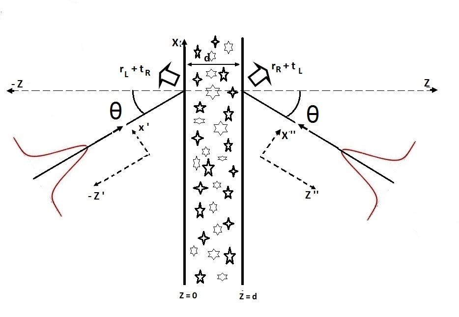
It is considered, two identical Gaussian beams, incident from opposite sides of CM slab at the same incidence angle with the z axis (oriented along the normal to the flat surfaces of a CM or CPA medium) (Fig. 1) and & axis. The CPA medium consists of a metal-dielectric composite layer of thickness and is assumed non-magnetic. The plane at and are the plane of incidences which are the two interfaces of the CPA medium. Henceforth, author uses the label and for left and right propagating wave incident from left and right side respectively, so that the resulting reflected and transmitted waves are denoted as , , and respectively. Thus the total scattering amplitude at the interface is given by . This must be same as the total scattering amplitude at the interface given by ; since the medium of incidence and emergence are the same due to symmetry of the structure implies and . In the next section we have discuss the characteristics of CM.
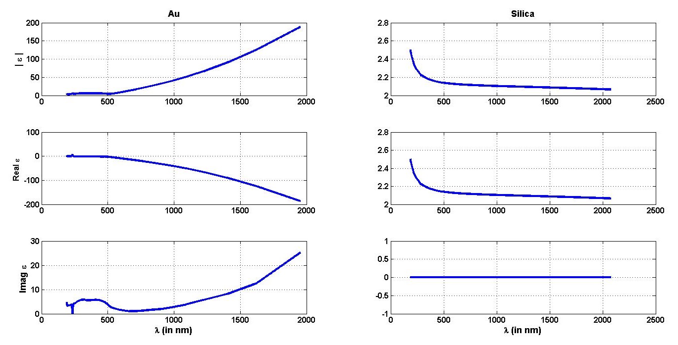
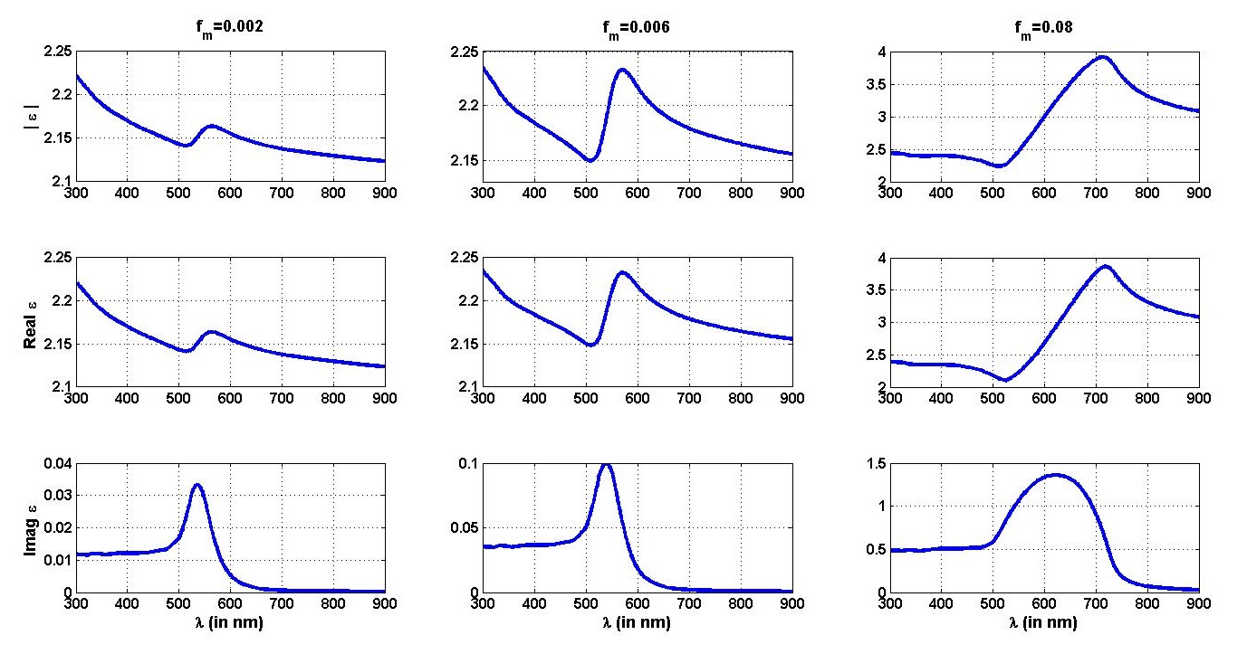
CM is homogeneous mixture of metal and dielectric. Here, it is made of gold () and silica (). The optical constant of gold twenty one and dielectric twenty is interpolated nineteen and calculated the permittivity for all wavelengths in the optical region. In figure 2 with respect to wavelength the absolute, real and imaginary value of permittivity for metal, dielectric and CM with different volume fraction () was plotted. To find the effective dielectric function or the permittivity of CM, the Bruggeman effective medium theory (BEMT) sixteen ; seventeen is being used; which is state as follows.
| (1) |
Where, , , and are permittivity and volume fraction of metal and dielectric respectively.
Here, I have shown in the fig 2, characteristic changes in CM in different volume fraction and of gold () in the range of 300 to 900 nano-meters, where, the absolute, real and imaginary of permittivity of CM can seen.
The CM is illuminated from both side by two identical Gaussian beam sources with equal - intensity, beam spot, wavelength and angle of incident on the CM. For I choose three Cartesian coordinate system, denoted as un-prime, prime and double-prime axis as in the fig 1. Therefore the transformation matrix at and are as follows.
| (2) | |||||
| (3) |
Then the equations of two such Gaussian beams are propagating along and axis are represented as follows.
| (4) | |||||
| (5) |
Where the beam parameters are and . By definition, irrespective of prime or double prime coordinate, the basic beam elements are wave vector, ; beam waist size,
; radius of curvature, ; Rayleigh range, ; Gouy phase, .
For simplicity, we assume that the amplitude fields in the beams, have a Gaussian spatial distribution only in the plane of incidence, along the axis perpendicular to the direction of wave propagation and are independent of the coordinate perpendicular to the plane of incidence. As there is well known, for a paraxial Gaussian beam profile spreading along & axis, the wave front of the beam no longer remain planar but acquire a radius of curvature and at distance and respectively away from the beam waist (Located at and ). In other words the Gaussian beam can be regarded as a collection of plane waves of slightly differing (about a central) wave vector. Thus the angular spectrum representation of the Gaussian beam are of the form for and
| (6) | |||||
| (7) |
After substituting eq (2), eq(4) in eq(6) and eq(3), eq(5) in eq(7) one can reach into following equation.
| (8) |
The incident beams are focused at the interfaces (z = 0 and z = d). The above angular spectrum beam become nothing but infinite number of plane wave which we numerically evaluate. Then each and every such plain waves goes through Fresnel’s reflection and transmission coefficient formulas; which gives reflected and transmitted amplitudes at z = 0 and z=d or at the interfaces. Then, added up of one side scattering amplitude (SA) i.e. reflection amplitude with either side transmitted amplitude. At last, inverse Fourier transformation of SA gives the actual beam profile which is comes out which can be written as
| (9) |
The angular spectrum decomposition of the Gaussian beam using Fourier transformation leads to infinite number of plane wave keeping the profile same, because Fourier transformation of a Gaussian is a Gaussian. Each decomposed plane wave obeys Fresnel’s reflection and transmission formalism twenty two . So each of decomposed beam wave is multiplied by the corresponding reflection and transmission coefficient. Thereafter an inverse Fourier transform leads to the reflected and transmitted beam profile at and respectively.
III Calibrations, Numerical results and discussions
The CM (nonmagnetic) is taken to be a gold dielectric composite layer of thickness d (). The effective dielectric constant of the composite is calculated using Bruggmann effective theory using the following parameters;
a filling factor for gold whose dielectric constant at a discrete wavelength, nm which is taken from Johnson’s and Christy’s twenty one experimental data’s interpolating result. The dielectric constant of the dielectric (silica) is, .
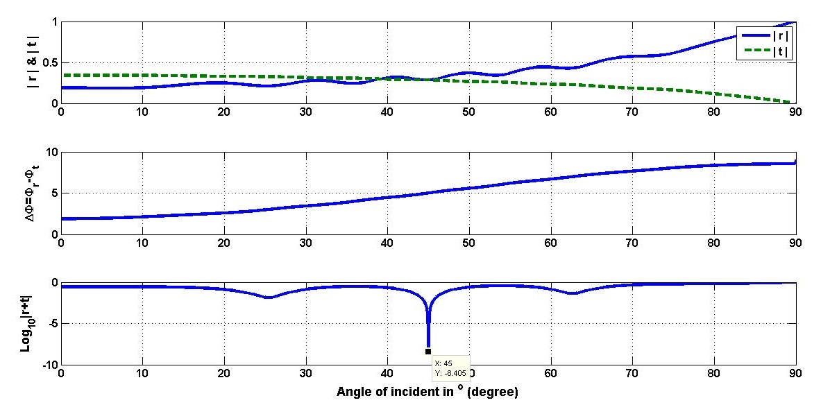
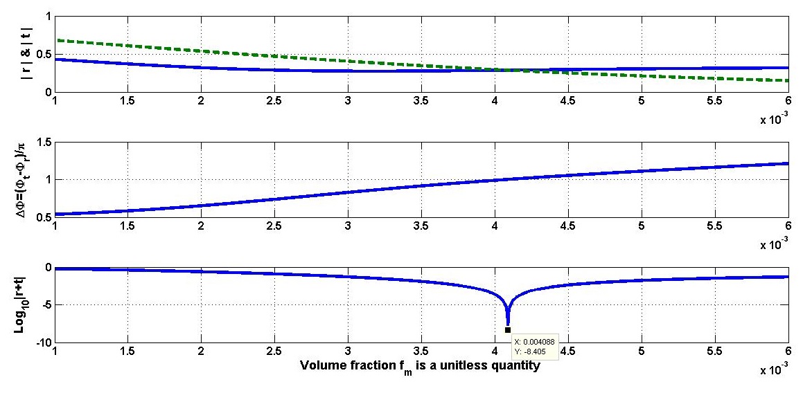
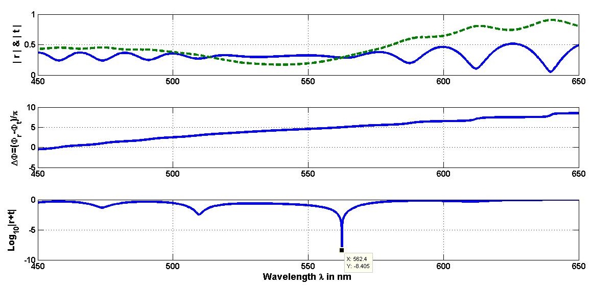
The thickness of the slab . The calculated permittivity of CM is . An important aspect is to determine of the angle of incidence and the wavelength of the incident fields at which maximum absorption is observed. If one can look into figure 3, I have taken individual observation for five angle of incident ( angle), volume fraction of CM (Gold and Silica) and wavelength of two monochromatic infinitely stretched plane wave nm fall into CM from opposite side. It is observed, that about times scattering amplitude came out comparing to the incident amplitudes. While taking simultaneous observation, the remaining parameters are taking constant. Now, in the next para, replacing the plane waves with Gaussian beams as state follows.
Two identical Gaussian beam both having minimum beam spot size , wavelength nm focused on the wall of the slab of CM, is propagating along and axis have an incident angle and with axis respectively. In the numerical calculations and , where is taken.
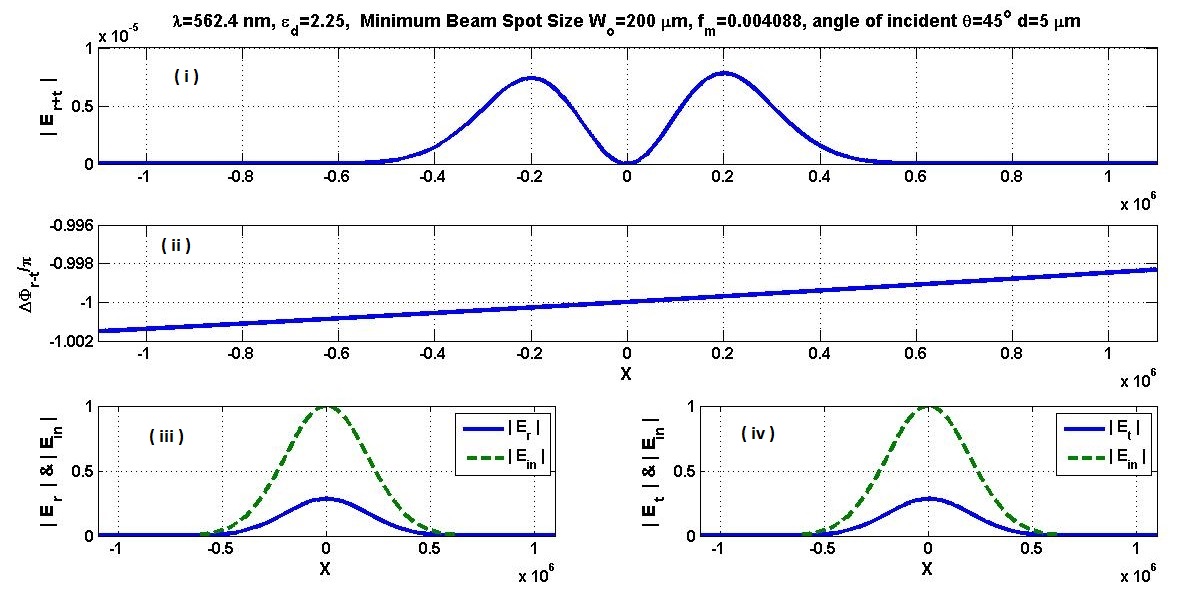
In the figure 4(i) is the output or resultant beam profile, which can also called scattering amplitude when two identical Gaussian beams ( nm, , m, m and ) focused from the opposite side on CM. One can see the scattering amplitude is of the order of comparing to the incident amplitude. The next figure 4(ii) shows about phase change through out the scattering profile amplitude. In figure 4 (iii) and (iv) are showed reflection and transmission beam profile respectively with blue line there are also comparing with incident beam profile is shown in green dotted line while shining the Gaussian beam on CM from one side.
In fig 5, it has observed, simultaneously, the output beam profile as well as it’s corresponding phase while changing different physical parameters such as width of CM (), volume fraction (), wavelength of incident beam () and beam waist size () respectively when keeping remaining parameters are in constant.

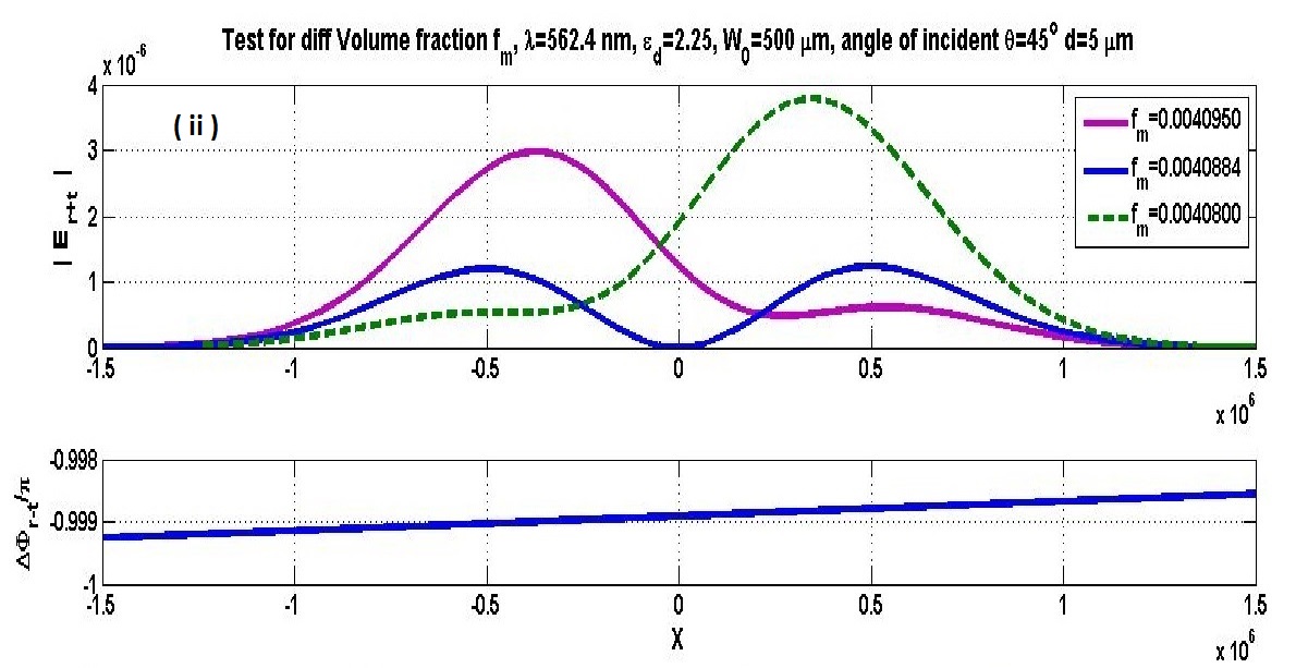
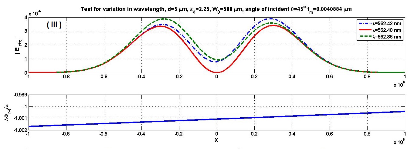
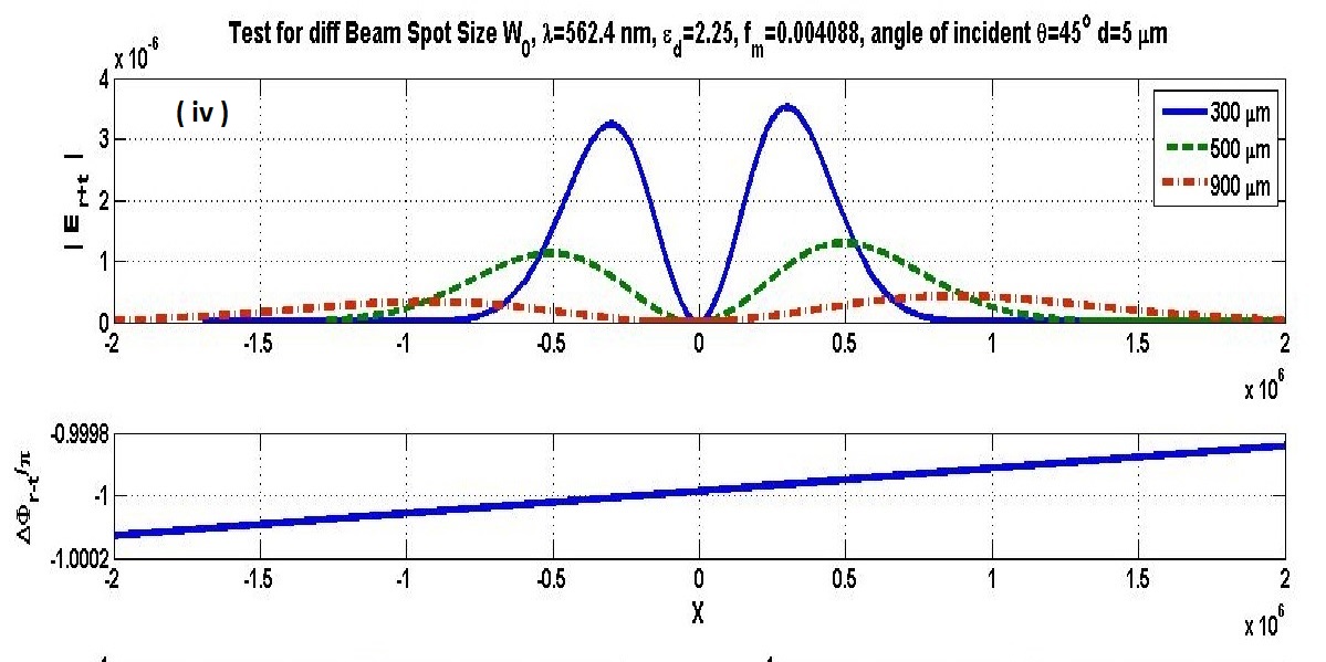
In the fig 5(i), , and in m are taken when nm, , m and keeps as constant. We have observed by small changing in volume fraction (, and ) to observe (fig 5(ii)), the resultant beam front keeping m and remaining parameter constant. In figure 5(iii), making slight change in wavelength (562.42, 562.40 and 562.38 nm) taken the observation when m, and remaining parameter constant. And lastly for three different of beam waist size (300, 500 and 900 m) while m, , nm and the remaining parameters are keeping same.
IV Conclusion and remarks
Here, it is studied coherent perfect absorption (CPA) in metal (Gold) - dielectric () composite medium (CM) on orthorhombic shaped slab. Here, it is considered, two identical Gaussian beams incident on the slab from the opposite end with the same incident angle with z axis. The permittivity of metal and CM is approximated by Johnson and Christy’s “optical constant of novel metals” and Bruggeman effective medium theory respectively. I have shown, CPA can be observed with Gaussian beams. Here, the central part and the peripheral parts of the beam is completely absorbed whereas the absorption is reduced in the middle parts of the resultant beam’s with incident angle. From the figure 4, we observed a licking of the order of with respect to incident beam amplitude; i.e. minimum 99.9996% is absorbed of the incident beam due to critical coupling in the composite medium. CPA can occur even for moderately focused Gaussian beams which typically are generated in the laboratories and for utilization in experimental studies of optical problems. A detailed analytic discussion of CPA scattering of fundamental Gaussian beam as a function of different physical parameters of the system was carried out. These results and observations can use in many physics and optical problem.
Acknowledgements
Author is thankful to Suneel Singh for his useful suggestions and discussions. He is also thankful to UGC (Govt. of India) for financial support.
References
- (1) Y. D. Chong,fig L. Ge, H. Cao, and A. D. Stone; “Coherent Perfect Absorbers: Time-Reversed Lasers” Phys. Rev. Lett. 105, 053901 (2010).
- (2) W. Wan, Y. D. Chong, L. Ge, H. Noh, A. D. Stone, and H. Cao, “Time-reversed lasing and interferometric control of absorption”, Science 331, 889-892 (2011).
- (3) S. Longhi, “Coherent perfect absorption in a homogeneously broadened two-level medium”, Phys. Rev. A 83, 055804 (2011).
- (4) S. Thongrattanasiri, F. H. L. Koppens and F. J. G. de Abajo; “Complete Optical Absorption in Periodically Patterned Graphene”, PRL 108, 047401 (2012).
- (5) S. Dutta-Gupta, O. J. F. Martin, S. Dutta Gupta, and G. S. Agarwal, “Controllable coherent perfect absorption in a composite film”, Optics Express 20, 1330 (2012).
- (6) S. Duttagupta, R. Deshmukh, A. V. Gopal, O. J. F. Martin and S. Duttagupta; “Coherent perfect absorption mediated anomalous reflection and refraction”, Optics Letters, Vol. 37, Issue 21, pp. 4452-4454 (2012).
- (7) S. Longhi, “PT-symmetric laser absorber”, Phys. Rev. A 82, 031801(R) (2010).
- (8) Ming Cai, Oskar Painter, and Kerry J. Vahala; “Observation of Critical Coupling in a Fiber Taper to a Silica-Microspherefig Whispering-Gallery Mode System”, PRL Vol. 85 no 74(4) (2000).
- (9) Jonathan R. Tischler, M. Scott Bradley and Vladimir Bulovic; “Critically coupled resonators in vertical geometry using a planar mirror and a 5 nm thick absorbing film”, Opt Lett, Vol. 31, 13, pp. 2045-2047 (2006).
- (10) S. Dev, S. Duttagupta, J. Banerji and S. Duttagupta; “Critical coupling at oblique incident”, J. Opt. A, Pure Appl. Opt. 9, 555-559 (2007).
- (11) S. Duttagupta, “Strong interaction mediated critical coupling at two distinct frequencies”, Opt Lett, Vol. 32, 11, pp. 1483-1485 (2007).
- (12) L. I. Perez, “Reflection and non-specular effect of 2D Gaussian beam in interfaces between isotropic and anisotropic media”,6 J. Modern Optics Vol. 47, Issue 10, 1645-58(2000).
- (13) H. Noh, Y. Chong, A. D. Stone, and H. Cao “Perfect coupling of light to surface plasmons by coherent absorption”, PRL 108, 186805 (2012).
- (14) Book - “Quantum Electronics” (third Ed) by A. Yariv.
- (15) Book - “Principle of Optics” by M. Born and E. Wolf.
- (16) Book - “Absorption and Scattering of Light by Small Particles” by C. F. Bohren and D. R. Huffman.
- (17) Book - “Optical Metamaterials: Fundamentals and Applications” by W. Cai and V. Shalaev.
- (18) Book - “Principle of nano optics” by L. Novotny and B. Hecht.
- (19) Book - “Mathematical Method” by S. Hassani.
- (20) Book - “Handbook of Optical Constant of Solids” by E. D. Palik.
- (21) P. B. Johnson and R. W. Christy; “Optical Constants of the Noble Metals” Phys. Rev. B 6, 4370-4379 (1972).
- (22) S. Dutta Gupta, “Nonlinear optics of Stratified media”, Progress in Optics, E.Wolf, ed.(Elsevier Science, 1998), Vol. 38, p.1.