BEAM-BEAM COMPENSATION STUDIES IN THE TEVATRON
WITH ELECTRON
LENSES
Abstract
At the Fermilab Tevatron collider, we studied the feasibility of suppressing the antiproton head-on beam-beam tune spread using a magnetically confined 5-keV electron beam with Gaussian transverse profile overlapping with the circulating beam. When electron cooling of antiprotons was applied in regular Tevatron operations, the nonlinear head-on beam-beam effect on antiprotons was small. Therefore, we first focused on the operational aspects, such as beam alignment and stability, and on fundamental observations of tune shifts, tune spreads, lifetimes, and emittances. We also attempted two special collider stores with only 3 proton bunches colliding with 3 antiproton bunches, to suppress long-range forces and enhance head-on effects. We present here the results of this study and a comparison between numerical simulations and observations. These results contributed to the application of this compensation concept to RHIC at Brookhaven.
1 INTRODUCTION
The nonlinear forces between colliding beams are one of the main performance limitations in modern colliders. Electron lenses have been proposed as a tool for mitigation of beam-beam effects [1]. It was demonstrated that the pulsed electron current can produce different betatron tune shifts in different proton or antiproton bunches, thus cancelling bunch-to-bunch differences generated by long-range beam-beam forces [2, 3, 4]. In these experiments, the electron beam had a flat transverse current-density distribution, and the beam size was larger than the size of the circulating beam. To first order, the effect of the electron lens was a bunch-by-bunch linear betatron tune shift.
The present research went a step further. We studied the feasibility of using the magnetically confined, nonrelativistic beam in the Tevatron electron lenses to compensate nonlinear head-on beam-beam effects in the antiproton beam. For this purpose, the transverse density distribution of the electron beam must mimic that of the proton beam, so that the space charge force acting on the antiprotons is partially canceled. The betatron phase advance between the interaction points and the electron lens should be close to an integer multiple of .
During regular Tevatron operations, both stochastic and electron cooling were used to reduce the transverse emittance of antiprotons. Under these conditions, antiprotons were transversely much smaller than protons, making head-on effects essentially linear. Intensity loss rates of antiprotons due to beam-beam were caused by long-range interactions and rarely exceeded 5% per hour. While an improvement of the Tevatron performance by head-on beam-beam compensation was not foreseen, we were interested in the feasibility of the concept and in providing the experimental basis for the simulation codes used in the planned application of electron lenses to the RHIC collider at BNL [5, 6, 7].
2 EXPERIMENTAL APPARATUS
| side view | top view |
 |
 |
 |
 |
| measured current-density profiles | |

| [m] | [m] | [] | ||||
|---|---|---|---|---|---|---|
| CDF | 0.30 | 0.30 | 0.0 | 0.0 | 6.63 | 6.85 |
| DZero | 0.50 | 0.50 | 0.0 | 0.0 | 13.77 | 13.85 |
| TEL2 | 68 | 153 | 1.2 | 1.0 | 3.17 | 3.22 |
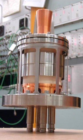
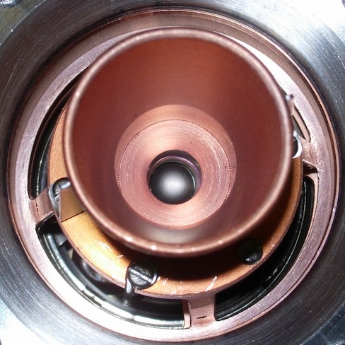
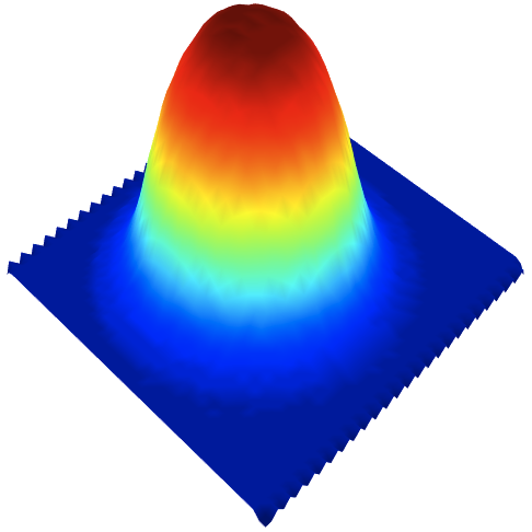
An electron gun based on a convex tungsten dispenser cathode operating at a temperature of 1400 K was designed and built [8]. The diameter of the cathode was 10.2 mm (0.4 in). Its shape and the geometry of the electrodes were chosen to produce a current density profile close to a Gaussian distribution. Figure 1 shows pictures of the electron gun and an example of a current density measurement. The maximum peak current yield was 0.5 A at a cathode-anode voltage of 4.6 kV. The standard deviation (rms) of the current profile distribution was at the gun.
The electron gun was installed in the second Tevatron electron lens (TEL2) in June 2009 (Figure 2). In the electron lens, the beam was generated inside the gun solenoid (0.1–0.4 T) and guided by a superconducting solenoid (1–6 T) through the 3-m overlap region, where it interacted with the circulating beams (protons or antiprotons) before being extracted and dumped in the collector. The size of the electron beam in the overlap region was controlled by the ratio between the magnetic field in the gun solenoid and in the main solenoid : . Distortions of the electron beam profile due to its space-charge evolution were mitigated by the large axial field ().
In the Tevatron, 36 proton bunches (referred to as P1–P36) collided with 36 antiproton bunches (A1–A36) at the center-of-momentum energy of 1.96 TeV. There were 2 head-on interaction points (IPs), corresponding to the CDF and the DZero experiments. Protons and antiprotons circulated in the same vacuum pipe on helical orbits. Their separation at TEL2 was 9 mm (about 6 mm both horizontally and vertically). Each particle species was arranged in 3 trains of 12 bunches each, circulating at a revolution frequency of 47.7 kHz. The bunch spacing within a train was 396 ns, or 21 rf buckets at 53 MHz. The bunch trains were separated by 2.6-s abort gaps. The synchrotron frequency was 34 Hz, or times the revolution frequency. The machine operated with betatron tunes near 20.58. The relevant lattice functions are reported in Table 1. Thanks to the special 5-kV high-voltage modulator (200-ns rise time), the electron beam could be synchronized with any bunch or group of bunches, and its intensity could be varied bunch by bunch [9].
3 RESULTS
Experiments on beam-beam compensation with Gaussian electron beams were carried out between September 2009 and July 2010. Preliminary results were discussed in Refs. [10, 11].
3.1 Beam Alignment and Loss Patterns

Because of the nonlinear fields, alignment between electrons and antiprotons was critical. We performed several position scans to ensure that the response of the beam position monitors was accurate for both fast signals from antiproton bunches and for slower signals from electron pulses. These position scans were also useful to assess the effects of misalignments on losses and to compare the experimental results with numerical calculations. We simulated losses during a vertical alignment scan using the weak-strong numerical tracking code Lifetrac [12]. The model included the full collision pattern for the relevant antiproton bunch and a thin-kick Gaussian electron beam implemented via an analytical formula. The beam parameters corresponded to the conditions at the time of the measurement at the end of Store 7718. We tracked a bunch of 5 000 macroparticles for turns for various vertical electron beam misalignments and evaluated the intensity loss rate. The simulation reproduced several features observed in experiments. First, the simulation performed at the nominal antiproton working point (tunes set to , ) predicted no losses for any value of the vertical misalignment. This was also observed experimentally: at the nominal working point, the electron beam did not cause any additional beam loss. Similarly to the experiment, the verical tune in the simulation had to be lowered by 0.003 to produce particle losses. Moreover, the simulation at the modified working point demonstrated the characteristic double-hump structure of the loss rate as a function of offset. The position of peaks was in good agreement with the measurements. Figure 3 shows the measured loss rates (red crosses) and the simulated decay rates (blue crosses and lines). Both electron and antiproton vertical rms beam sizes in the overlap region were equal to 0.6 mm.
3.2 Incoherent Tune Shifts and Tune Spread

The effect of the electron lens on the incoherent tune distribution could be observed directly during dedicated antiproton-only stores, when there was no contamination from protons in the 21-MHz Schottky signal. Figure 4 shows the vertical Schottky signal as a function of electron lens current. The vertical tick marks indicate the expected magnitude of the linear beam-beam parameter due to electrons with Gaussian standard deviation and velocity at a location where the amplitude function is :
| (1) |
Here, represents the classical radius of the proton and is the relativistic factor of the circulating beam. As expected, a downward shift and widening of the antiproton tune distribution is observed. The width of the vertical tune line agrees well with the hypothesis that represents the maximum tune shift.
3.3 Effects on Coherent Beam-beam Modes

A system for bunch-by-bunch measurements of transverse coherent beam-beam oscillations was developed [13, 14]. It was based on the signal from a single beam-position monitor in a region of the ring with high amplitude functions. Because of its high frequency resolution and its single-bunch capability, this system complemented the Schottky detectors and direct-diode-detection base-band tune monitor. It was conceived as a possible tool to monitor beam-beam compensation effects.
Figure 5 shows the signal from a single antiproton bunch towards the end of a regular collider store (Store 7719). The top plot shows the spectrum of coherent modes under nominal conditions. The linear beam-beam parameter per interaction point was 0.0050 for antiprotons and 0.0023 for protons. The middle plot corresponds to the electron lens acting on the bunch, with . For comparison, the bottom plot shows the effect of lowering the vertical antiproton tune by 0.0022. In the middle plot, one can see a downward shift of the first eigenmode and a suppression of the second. This suppression could be caused in part by the antiproton tune moving away from the proton tune. A considerable change in the width of the first coherent mode was also observed, but relating the reduced width of the coherent mode to a narrower tune distribution (as one would expect if there was beam-beam compensation) requires further investigation and numerical simulations.
3.4 Tune Scans with Dedicated Head-on-only Stores


To enhance head-on effects and to suppress long-range forces in the Tevatron, two special 3-on-3 collider stores were attempted. In these stores, 3 proton bunches collided with 3 antiproton bunches. The bunches were equally spaced around the machine. Antiprotons were intentionally heated to increase their emittance and approach the size of proton bunches. Unfortunately, during the first experiment, the emittances of two proton bunches increased dramatically between the beta squeeze and collisions, before the beginning of the study. Hence, the store could not be used for our purposes.
A smaller blow up of proton emittances occurred before the second study as well, making conditions far from ideal: the antiproton beam-beam parameter was less than 0.015, electron sizes could not be matched to proton sizes, and the attempt to increase the size of the electron beam resulted in a reduced compensation strength (). Nevertheless, several tune scans were performed, both vertically and diagonally in the tune diagram.
Figure 6 shows the measured decay rates for the 3 antiproton bunches as a function of the average tune (from the 1.7-GHz Schottky detector) during a diagonal scan: the bunch affected by the electron lens (A25, magenta), the control bunch (A13, dark blue), and the bunch colliding with the two least dense proton bunches (A1, green). Lifetimes and tune space were obviously better for A1. The tune shift of the affected bunch with respect to the control bunch is compatible with the expected amount (0.002), but it is too small to be clearly observed. Some resonances (4/7 and 7/12, for instance) appear stronger with the lens on, whereas the 3/5 is weaker (or shifted). One may observe that, as expected, beam-beam forces appear to drive the even resonance 7/12 (large difference between the green and the blue points), but not the odd resonance 4/7 (control bunch and low-beam-beam bunch have similar lifetimes). There are regions of the working point where the bunch affected by the electron lens had better lifetime (0.560–0.568 and 0.592–0.598), but this special 3-on-3 store was not enough to clearly see a reduction in tune spread or an improvement in the available tune space.
Nevertheless, these measurements provided useful information on the available tune space for comparisons with simulation codes. Figure 7 shows the antiproton intensity decay rates and emittance growth rates calculated with Lifetrac as a function of tune in a diagonal scan. The horizontal scale is the bare lattice tune plus half of the beam-beam parameter, in order to simulate the average of the incoherent tune distribution. As the tune approaches the 7th order resonance (0.571) from above, loss rates increase dramatically. Increasing the tune towards the 5th order resonance (0.6) causes emittance growth. According to this calculation, with the nonideal experimental conditions described above, the electron lens does not cause harm in the stable region, but it can make things worse outside. The region of available tune space is well reproduced by the simulations.
4 CONCLUSIONS
The first studies of beam-beam compensation with Gaussian electron lenses were carried out at the Tevatron.
We found that, in spite of the very different time structure of the antiproton bunch and of the electron pulse, alignment of the electron beam with the circulating beam using a common beam position monitor was accurate to within 0.1 mm and reproducible from store to store.
We observed the effects of the electron lens on beam lifetimes and tunes. At the nominal working point in tune space, the electron lens did not have any adverse effects on the circulating beam, even when intentionally misaligned. With only antiprotons in the machine, the tune shift and tune spread caused by the electron lens were clearly seen.
Dedicated collider stores with only 3 bunches per species (no long-range interactions) were attempted, but the experimental conditions were not ideal. The data was used for code benchmarking. Moreover, tune scans conducted during these special stores provided a direct comparison between the lifetimes of a control antiproton bunch, a bunch affected by the electron lens, and a bunch experiencing reduced beam-beam forces.
The machine was not ideal for a direct demonstration of the beam-beam compensation concept for two main reasons: head-on nonlinearities for cooled antiprotons were weak during normal operations; and the lattice requirements (zero dispersion, phase advance close to an integer multiple of ) were not exactly met at the electron lens. Nevertheless, several key experimental observations were made.
5 ACKNOWLEDGMENTS
The authors would like to thank W. Fischer and C. Montag (BNL) for their suggestions on experiment design and for participating in part of the studies, and V. Shiltsev (Fermilab) for discussions and insights. We are grateful to the Operations Department in Fermilab’s Accelerator Division for making these experiments possible.
Fermi Research Alliance, LLC operates Fermilab under Contract No. DE-AC02-07CH11359 with the United States Department of Energy. This work was partially supported by the US LHC Accelerator Research Program (LARP).
References
- [1] V. Shiltsev et al., Phys. Rev. ST Accel. Beams 2, 071001 (1999).
- [2] V. Shiltsev et al., Phys. Rev. Lett. 99, 244801 (2007).
- [3] V. Shiltsev et al., New J. Phys. 10, 043042 (2008).
- [4] V. Shiltsev et al., Phys. Rev. ST Accel. Beams 11, 103501 (2008).
- [5] W. Fischer et al., in Proceedings of the 2012 International Particle Accelerator Conference (IPAC12), New Orleans, Louisiana, USA, 20–25 May 2012, p. 2125.
- [6] X. Gu et al., in Proceedings of the 2012 International Particle Accelerator Conference (IPAC12), New Orleans, Louisiana, USA, 20–25 May 2012, p. 2720.
- [7] Y. Luo et al., Phys. Rev. ST Accel. Beams 15, 051004 (2012).
- [8] V. Kamerdzhiev et al., in Proceedings of the 2008 European Particle Accelerator Conference (EPAC08), Genoa, Italy, 23–27 June 2008, p. 3500.
- [9] H. Pfeffer and G. Saewert, J. Instrum. 6, P11003 (2011).
- [10] A. Valishev et al., in Proceedings of the 2010 International Particle Accelerator Conference (IPAC10), Kyoto, Japan, 23–28 May 2010, p. 2084.
- [11] A. Valishev and G. Stancari, in Proceedings of the 2011 Particle Accelerator Conference (PAC11), New York, New York, USA, 28 March – 1 April 2011, p. 67.
- [12] D. Shatilov et al., in Proceedings of the 2005 Particle Accelerator Conference (PAC05), Knoxville, Tennessee, USA, 16–20 May 2005, p. 4138.
- [13] G. Stancari, A. Valishev, and A. Semenov, in Proceedings of the 14th Beam Instrumentation Workshop (BIW10), Santa Fe, New Mexico, USA, 2–6 May 2010, p. 363.
- [14] G. Stancari and A. Valishev, Phys. Rev. ST Accel. Beams 15, 041002 (2012).