- A/A
- Air-to-air
- A-EXEC
- Auto Execute COCR Service
- AAC
- Airline Administrative Control
- ACK
- Acknowledgement
- ACP
- Aeronautical Communications Panel
- AF
- Assured Forwarding
- AL
- Application Layer
- ANSP
- Air Navigation Service Provider
- AOC
- Airline Operational Control
- APC
- Air Passenger Communication
- APT
- Airport
- ATC
- Air Traffic Control
- ATI
- Access Technology Independent
- ATM
- Air Traffic Management
- ATN
- Aeronautical Telecommunication Network
- ATN/IPS
- Aeronautical Telecommunication Network / Internet Protocol Suite
- ATN/OSI
- Aeronautical Telecommunication Network / Open Systems Interconnection Reference Model
- ATS
- Air Traffic Services
- ATSC
- Air Traffic Service Communication
- AVBDC
- Absolute Volume Based Dynamic Capacity
- AWGN
- Additive White Gaussian Noise
- BB
- Bandwidth Broking
- BBFRAME
- Baseband frame
- BE
- Best Effort
- BER
- Bit Error Rate
- BGAN
- Broadband Global Area Network
- BSM
- Broadband Satellite Multimedia
- CA
- Constrained Architecture
- CAC
- Connection Admission Control
- CC
- Congestion Control
- CDMA
- Code Divison Multiple Access
- CLNP
- Connectionless Networking Protocol
- CLTP
- Connectionless Transport Protocol
- CoA
- Care of Address
- CoS
- Class of Service
- COCR
- Communications Operating Concept and Requirements for the Future Radio System
- COTP
- Connection Oriented Transport Protocol
- COTS
- Commercial-Off-The-Shelf
- CRA-CC
- CRA-Convolutional Code
- CRA-SH
- CRA-Shannon Bound
- CRA
- Contention Resolution ALOHA
- CRC
- Cyclic Redundancy Check
- CRDSA
- Contention Resolution Diversity Slotted ALOHA
- CRDSA++
- Contention Resolution Diversity Slotted ALOHA++
- CS
- Class Selector
- DAMA
- Demand Assigned Multiple Access
- DiffServ
- Differentiated Services
- DoD
- Department of Defence
- DSA
- Diversity Slotted ALOHA
- DSCP
- DiffServ Code Point
- DVB
- Digital Video Broadcasting
- DVB-RCS+M
- Digital Video Broadcasting - Return Channel via Satellite Mobility
- DVB-RCS
- Digital Video Broadcasting - Return Channel via Satellite
- DVB-S2
- Digital Video Broadcasting - Second Generation
- DVB-S2/RCS
- Digital Video Broadcasting - Second Generation / Return Channel via Satellite
- ECN
- Explicite congestion notification
- ECRA
- Enhanced Contention Resolution ALOHA
- ECTL
- Eurocontrol
- EF
- Expedited Forwarding
- ENR
- En-Route
- ES
- End System
- ESA
- European Space Agency
- ETSI
- European Telecommunications Standards Institute
- ETSI-BSM
- European Telecommunications Standards Institute - Braodband Satellite Multimedia
- FAA
- Federal Aviation Administration
- FCA
- Free Capacity Assignment
- FDM
- Frequency Division Multiplexing
- FEC
- Forward Error Correction
- FET
- First Entry Times
- FL
- Forward Link
- GEO
- Geostationary Orbit
- GIG
- Global Information Grid
- GSE
- Generic Stream Encapsulation
- HA
- Home Agent
- HF
- High Frequency
- IC
- Interference Cancellation
- ICAO
- International Civil Aviation Organization
- IETF
- Internet Engineering Task Force
- IntServ
- Integrated Services
- IP
- Internet Protocol
- IPS
- Internet Protocol Suite
- IPSec
- IP Security
- IRA
- Irregular Repetition contention resolution ALOHA
- IRCRA
- Irregular Repetition Contention Resolution ALOHA
- IRSA
- Irregular Repetition slotted ALOHA
- IS
- Intermediate System
- IS-IS-TE
- Intermediate System to Intermediate System extension for Traffic Engineering
- ISI
- Input Stream Identifier
- ISO/OSI
- International Organization for Standardization/Open Systems Interconnection
- Ku
- Kurz-under
- Ka
- Kurz-above
- KL-d
- Kullback-Leibler divergence
- LAE
- Link Access Equipment
- LAN
- Local Area Network
- LD
- Low Density
- LDACS
- L-band Digital Aeronautical Communication System
- L-DACS
- L-band Digital Aeronautical Communication System
- LDPC
- Low Density Parity Check Codes
- LEO
- Low Earth Orbit
- MAC
- Medium Access
- MCAST
- Multicast
- MF-TDMA
- Multifrequency Time Division Multiple Access
- MH
- Mobile Host
- MIHF
- Media Independent Handover Function
- MLPP
- Multi Level Priority Preemption
- Mode-S
- Mode-Select
- MPE
- Multi Protocol Encapsulation
- MPEG2-TS
- MPEG2 - Transport Stream
- MPLS
- Multi Protocol Label Switching
- NCC
- Network Control Centre
- NET
- Network Connectivity
- NEWSKY
- NEtWorking the SKY for aeronautical communications
- NOC
- Non-Operational Communication
- NSIS
- Next Steps in Signalling
- OC
- Operational Communication
- ORP
- Oceanic, Remote and Polar
- OSI
- Open Systems Interconnection
- OSPF
- Open Shortes Path First
- Probability Density Function
- PCE
- Predictive Capacity Estimation
- PCN
- Pre-Congestion Notification
- PDU
- Protocol Data Unit
- PEP
- Performance Enhancing Proxy
- PER
- Packet Error Rate
- PID
- Packet Identifier
- PLFRAME
- Physical Layer Frame
- PLR
- Packet Loss Rates
- QoS
- Quality of Service
- QoS-PRN
- QoS Private Relay Nodes
- QoS-RN
- QoS-Relay Nodes
- RA
- Random Access
- RBDC
- Rate Based Dynamic Capacity
- RCB
- Random Coding Bound
- RCS
- Return Channel via Satellite
- RCS+M
- Return Channel via Satellite plus Mobility
- RF
- Radio Frequency
- RFC
- Request For Comments
- RL
- Return Link
- RM
- Resource Management
- RN
- Relay Nodes
- RP
- replicas’ pointer
- RRM
- Radio Resource Management
- RS
- Reed Solomon
- RSVP
- Resource Reservation Protocol
- RTT
- Round Trip Time
- SA
- Slotted ALOHA
- SANDRA
- Seamless Aeronautical networking Through Integration of Data Links, Radios and Antennas
- SB
- Shannon Bound
- S2
- Second Generation
- SESAR
- Single European Sky ATM Research
- SF
- Superframe
- SIC
- Successive Interference Cancellation
- SLS
- Service Level Specification
- SNDCF
- Subnetwork Dependent Convergence Function
- SNIR
- Signal to Noise and Interference ratio
- SNR
- Signal-to-Noise ratio
- SWIM
- System Wide Information Management
- SYN
- Synchronization
- SYNC
- Synchronization
- TCP
- Transport Control Protocol
- TCP/IP
- Transport Control Protocol / Internet Protocol Suite
- TDMA
- Time Division Multiple Access
- TE
- Traffic Engineering
- TI
- Technology Independent
- TI-SAP
- Technology Independent - Service Access Point
- TD
- Technology Dependent
- TL
- Transport Layer
- TMA
- Terminal Maneuvering Area
- ToS
- Type of Service
- UCA
- Unconstrained Architecture
- UDP
- User Datagram Protocol
- VBDC
- Volume Based Dynamic Capacity
- VDL
- VHF Digital Mode
- VHF
- Very High Frequency
- VoIP
- Voice over IP
- VPN
- Virtual Private Networks
- WG
- Working Group
- WiMAX
- Worldwide Interoperability for Microwave Access
- XFECFRAME
- Forward Error Correction Frame
Optimum Header Positioning in Successive Interference Cancellation (SIC) based Aloha
Abstract
Random Access MAC protocols are simple and effective when the nature of the traffic is unpredictable and sporadic. In the following paper, investigations on the new Enhanced Contention Resolution ALOHA (ECRA) are presented, where some new aspects of the protocol are investigated. Mathematical derivation and numerical evaluation of the symbol interference probability after SIC are here provided. Results of the optimum header positioning which is found to be in the beginning and in the end of the packets, are exploited for the evaluation of ECRA throughput and Packet Error Rate (PER) under imperfect knowledge of packets positions. Remarkable gains in the maximum throughput are observed for ECRA w.r.t. Contention Resolution ALOHA (CRA) under this assumption.
I Introduction
Random Access (RA) Medium Access (MAC) protocols in the recent past have been intensively investigated especially coupled with multi-packet per user sending and SIC procedure. It was first proposed in [1] to send the same packet twice in different Time Division Multiple Access (TDMA) slots. Benefits in terms of delay and throughput were found under very moderate channel load conditions.
More recently, the idea to send multiple packets per user of [1] has been exploited for retrieving collided packets with the more effective SIC procedure in [2], [3], [4] and [5]. Contention Resolution Diversity Slotted ALOHA (CRDSA) presented in [2] is the first which applies SIC for trying to resolve packet collisions within a frame in a Slotted ALOHA (SA) like RA scheme.
CRDSA takes from [1] the idea to send more than one packet instance per user for each frame. But, on the other hand CRDSA is designed in a way to resolve most of packet contentions by using SIC. The key idea of CRDSA is to provide in each replica the signaling information of where the other replicas of the corresponding user are placed in the frame. This signaling information is stored in the so called replicas’ pointer (RP) section of the packet header. Every time a packet is recovered, this information can be exploited by the SIC procedure for removing the signal contribution of the other replicas from the frame, thus possibly removing its interference contribution to other packets. The main CRDSA advantages lie in an improved packet loss ratio and a much higher operational throughput.
The CRA protocol [4] exploits the same approach of using SIC as CRDSA, but in an Aloha-like RA scheme. Here no slots are present in the frame and thus the replicas of the users can be placed within the frame without constraints, except that replicas of a user may not interfere each other. The avoidance of slots results in significant advantages such as relaxation in synchronization requirements among users and possibility of varying packet length without padding overhead. Forward Error Correction (FEC) in CRA is beneficial also when no power unbalance among users is present, unlike in CRDSA, because partial interference is not only possible but also more probable than complete interference.
II ECRA and the replicas’ pointers
In [5] ECRA was first presented. The protocol is an evolution of CRA, where it is tempted to resolve loops among packets. Both CRDSA and CRA are not able to resolve collisions where the packets involved belong to the same users and the inter-packet interference is too high. These situations are called loops. Suppose we are sending two packets per user and we are using the CRDSA protocol. Suppose further, a collision involving both the packets belonging to the two users happens. In this case there is no possibility to recover the two packets sent, and this results in a complete loss of the information stored in the users’ packets. If the CRA protocol is employed, the situation is more complex. In fact, the collision between the two users’ packet can be partial, that is only a portion of the packets can be involved in the collision. For an example of loops see figure 1. We can suppose in our case, although FEC is used for counteracting the interference coming from the packets’ collisions, the level of interference is too high for correct decoding of the packets. Also in this second case the loop cannot be resolved and the users’ packets cannot be retrieved.
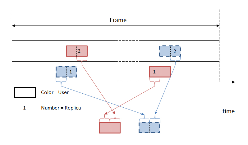
In ECRA it can be observed that the partial collision of an Aloha like RA scheme involves different parts of the packet, unlike CRDSA where the collisions are always involving the packets entirely. Therefore, starting from the SIC algorithm of the CRA protocol, a further step is introduced where a combined packet is created from the two (or more) user’s replicas. The combined packet is composed in a way such that the resulting Signal to Noise and Interference ratio (SNIR) is maximized, as presented in [5]. In particular, for each symbol of one packet, the one belonging to the replica with less interference is selected to be used in the combined packet. In the case of figure 1 we can see how the combined packet of ECRA will be created. Due to the higher SNIR further packets can be retrived from the frame, increasing the throughput performance and decreasing the PER w.r.t. CRA. An increase up to 26% in the peak throughput is achieved by ECRA w.r.t. CRA as shown in [5]. The key assumption there is the perfect knowledge of all the packets positions within the frame after the first step of SIC. Differently from [6], where an iterative chunk-by-chunk decoding between the collided packets is employed, in ECRA an entire combined packet is constructed and the decoding attempted on it in one step. Moreover, in ECRA the replicas generation is made regardless of the decoding success, while in [6] only the collided packets are replicated.
III Optimum replicas’ pointers position
In RA protocols without slots and with SIC such as [4] and [5], the packets are sent randomly within a frame. Therefore, when a collision between two packets happens, the quantity of symbols involved in that collision is uniformly distributed between 1 and the length of the packet . If we consider the whole set of collided packets, it can be shown that the probability of collision for every symbol within the generic packet, is equal for all the symbols, for . Since every symbol has the same probability to face interference, there is no way to optimize the header positioning in the packet in order to minimize the probability to have interference in these sensitive sections.
However an interesting question is, whether sections of the packets can be found which are less subject to interference, if interference cancellation is applied. To address this question let us first consider the simplest interference case of only two packets interfering each other.
III-A Case I: Two interfering packets
First we assume that the colliding packets are symbol synchronized, hence, when a symbol is involved in a collision it is entirely collided. Second we assume perfect SIC, therefore all the decodable packets are correctly received and ideally removed from the frame. Third, the received packet power is the same for all the packets. Fourth, the decoding threshold is assumed to be the Shannon capacity limit and thus, we are considering Gaussian inputs. According to [4] and [5] we can write the SNIR decoding threshold as , given the rate . We can also write the SNIR of user and replica as . The quantity is the interference ratio suffered by the packet of user and replica , e.g. means that one packet is entirely colliding with the given packet. Every packet with is correctly received, thanks to the fourth hypothesis. We are interested in determining the quantity which is the maximum percentage of interference for which a packet is still decodable at the receiver. This value can be derived by the equation
| (1) |
where we can define Signal-to-Noise ratio (SNR) as . This leads to
Thus, can be determined when the rate and the packet’s are defined. For a better understanding of the scenario, let us divide the two interfering packets case in two subcases and .
III-A1
We are interested in determining the number of possible cases , where two packets are interfering. Since the packets are symbol synchronized, this number is finite and is . This value can be derived observing that at least one symbol of the two packets needs to be interfered. In order to ensure this, we have possible interference cases among two packets, which lead to the value of .
Let us now define , where represents the minimum number of symbols that make a packet undecodable. Due to the second hypothesis, all the packets with symbols interfered were already correctly decoded. Therefore, after the SIC process the number of possible cases , where two packets are interfering reduces to
Intuitively, the formula derives directly from the previous reasoning, where instead of one, at least L symbols need to be interfered.
We now want to determine the probability of interference for each symbol in the packet for . Since , it follows that and therefore some of the central symbols of the packet must face interference with probability equal to 1. The exact position of these symbols within the packet is related to . We can observe that the least interference possible is when exactly symbols are involved in a collision. In this case the first symbols of the first packet collided and the last symbols of the second packet collided. Call the set of collided symbols of the first packet, and the set of collided symbols of the second packet. Explicitly
The intersection of symbols involved in the collision from both packets, are the ones with probability equal to 1 to be interfered. This can be derived by the observation that in all the other possible collisions, more than symbols are involved in the interference. Call the set given by ,
For every symbol outside , the probability of interference is . The symbol immediately before symbol , called , is involved in collisions in all the cases except one. The case where this symbol is not involved in the collision is when exactly the last symbols of the packet are interfering. In a similar way, the symbol immediately after symbol , called , is also involved in all the cases except one. If we iterate this reasoning until symbol in the backward direction and symbol in the forward direction, we find .
We are now able to formulate the interference probability for each symbol in the packet, as
| (2) |
III-A2
If we now consider the case of , the first observation is that the total number of cases where two packets are interfering is again, . It should be noted that the expression of is the same, but the actual value has changed because is different from the previous case. The second observation is that , because
| (3) |
The demonstration is the following, , leads to . Call the maximum of ,
| (4) |
For we are maximizing the left hand and minimizing the right hand of inequality (3),
Therefore, in this second case, no symbols have probability 1 to face interference. The maximum number of possible cases where a symbol is involved in collisions is , and the symbols that are involved in all these cases are with . This result can be found following the same reasoning presented in the previous paragraph with the appropriate differences. Moreover, the first and last symbol interference probability that can be computed applying the same procedure, is again .
We are now able to formulate the interference probability for each symbol in the packet, as
| (5) |
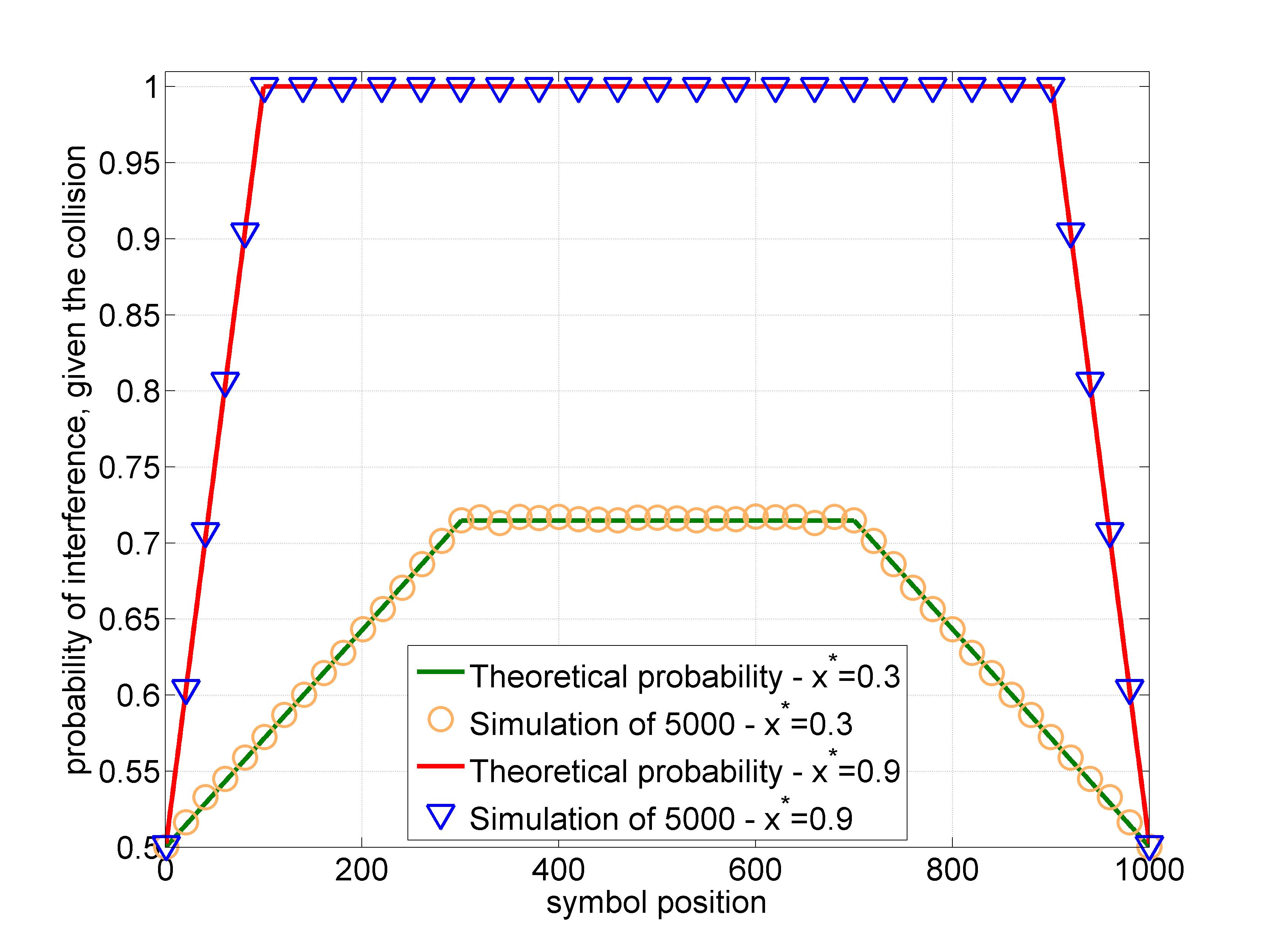
In figure 2 the comparison between the average empirical probability of symbol interference among 5000 collisions and the theoretical probability is presented. A packet length symbols and two representative thresholds, and , have been selected. In order to have a quantitative evaluation of the difference between the empirical and the theoretical probabilities, the Kullback-Leibler divergence (KL-d) has been evaluated. In particular
where , is the theoretical probability and is the empirical probability. The useful property of the KL-d is that if and only if for . Therefore, the closer is to 0, the more the empirical and theoretical probabilities are matching. In our case the distance gets for the case of and for . In both cases KL-d is very close to 0, which underlines the validity of the simulation results compared to the mathematical analysis.
In the case of , the symbols at the very beginning and the symbols at the very end of the packet have quite half of the probability to face interference with respect to the central symbols. In the case of this ratio reduces to , but it is still remarkable.
III-B Case II: Three or more interfering packets
The evaluation of the cases of three or more packets interfering is carried out with the help of simulations. Moreover, some qualitative remarks are provided in the following. If we start considering the case of and interference of three or more packets, we can make two considerations: first, there can be cases where the symbols in the packet center are free of interference, second, symbols in the beginning and in the end will have a higher probability of interference w.r.t. the two packets interference case as is shown in the simulations presented in figure 3. These two remarks are the effects of the same cause, if the collision involves more than two packets, in some cases the central section of one or more packets can be free from interference, but at the same time higher interference must be found at the beginning or at the end of the packet. The case of is slightly different, in fact not only the beginning and ending symbols will have an increased probability of interference w.r.t. the two interfering packets case, but also the central symbols will face interference more frequently. This is due to the increased number of combinations of interference that can be expected in the case of more than two packets interfering which lead to increased probability of interference among all the symbols in the packet.
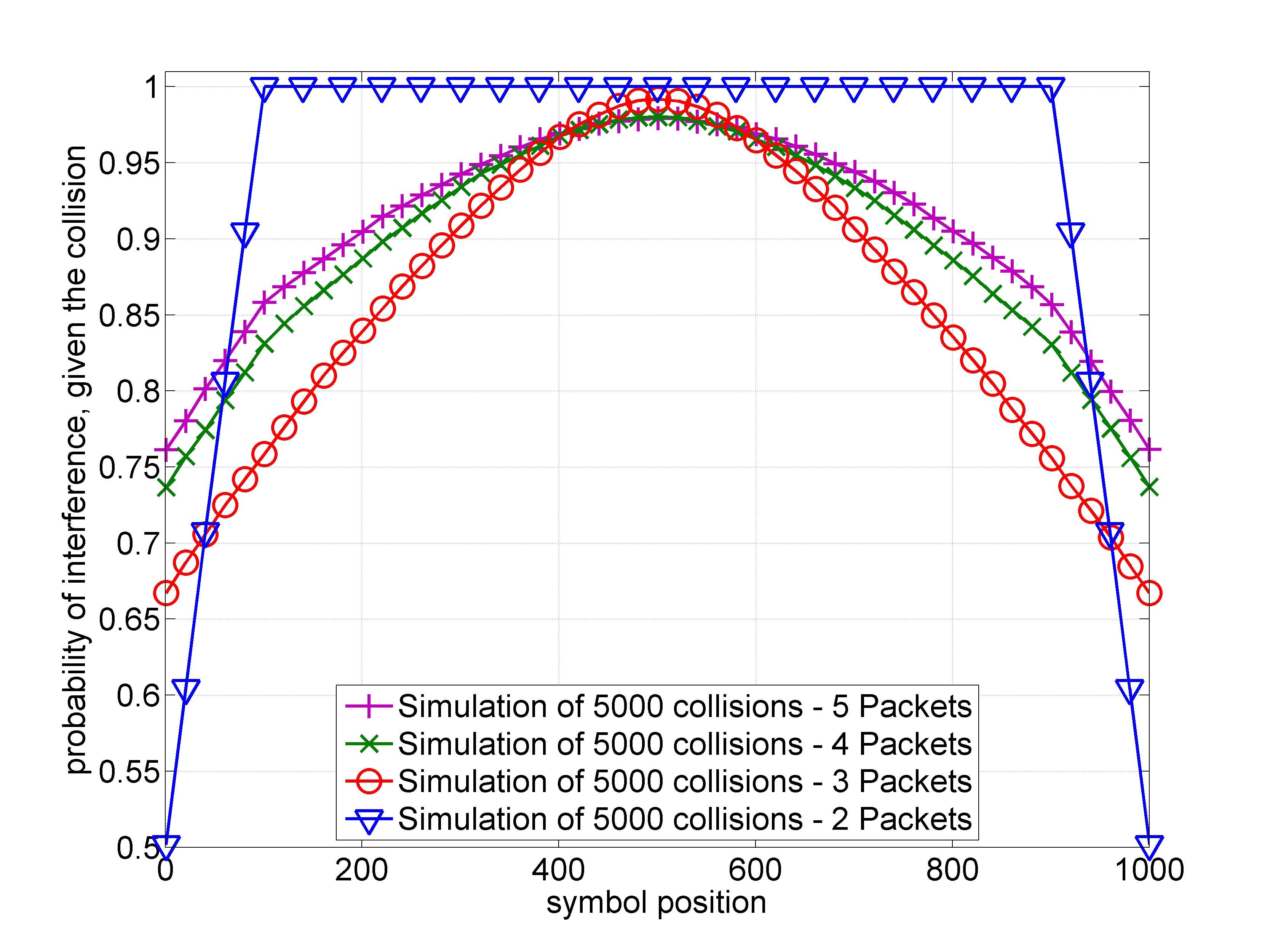
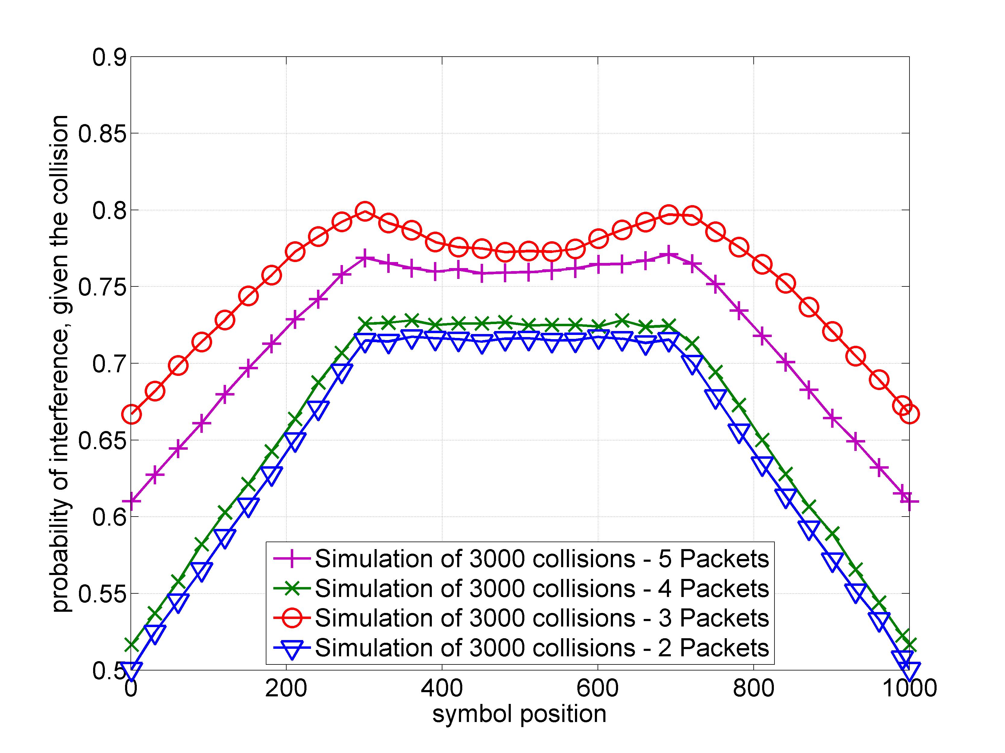
The symbol probability of every packet symbol for 2, 3, 4 and 5 packets colliding with is presented in figure 3 while the same symbol probability but with is presented in figure 4. All the aforementioned qualitative remarks are confirmed by the simulations. In figure 3 it can noted that already for three packets colliding, the probability of interference for every symbol is lower than 1. Furthermore, the beginning and ending symbols have more probability to be interfered w.r.t. the two packets colliding case. In case of , the results presented in figure 4 show an increase of symbol interference probability for all the symbol positions. It can be also noted in the case of , that for 3 packets colliding two peaks of interference probability can be found around and . This effect is smothered in case of 5 packets colliding. This fact can be qualitatively explained in the following way: when 3 packets collide and the minimum level of interference is considered, in one packet only one of the two border parts, the beginning section or the ending section, can be involved in the collision. Otherwise, when 4 packets collide the constraint disappears and both sections can be interfered.
A fundamental conclusion can be drawn from the results presented here, regardless the number of packets involved in a collision and regardless the decoding threshold, the symbols in the beginning and in the end of a packet are less frequently involved in collisions. The property can be exploited for a smart header positioning within the packet.
IV Numerical Results
Thanks to the result of the previous section, we know that positioning the header and therefore the RP in the beginning or in the end of a packet is the best choice for minimizing the probability of interference on it after the SIC process.
In the following results are provided for the probability of interference in the packet headers after the SIC procedure of CRA. The aim is first to show how the symbol interference probability evaluated in the previous section translates to packet header interference probability after SIC and second, to use this statistics for the ECRA throughput and PER simulations.
IV-A Header interference probability
The header length [symbols] is fixed to a certain value, in this example 10% of the packet length. Bigger headers will have too much impact on the overhead of the protocol, hence this choice can be seen as a worst case assumption on the header length. The header has a Cyclic Redundancy Check (CRC) code through which the decoder is able to recognize any impairment on this section of the packet. We assume that if one or more symbols of the packet header face interference, the header is not decodable and therefore we cannot retrieve the information about the replicas positioning of the user. The simulation assumptions are the following, the rate is selected and the SNR is dB equal for each user generating traffic. The frame duration is ms and the symbol duration is s. The packet length is bits and is equal for each user. If we fix the number of users , the offered traffic load is computed as .
Given and we can calculate the symbol length of the packet as symbols. The number of replicas sent by each user within a frame is . The maximum number of SIC iterations is chosen to be . In this way, a first step of SIC procedure is performed on the user packets at the decoder. The packets which have a sufficient SNIR can be correctly decoded and removed from the frame. In our simulations the Shannon capacity limit is assumed as decoding threshold according to (1). After the SIC procedure the packets which are still not decoded are checked and the ratio between the number of remaining packets and the number of packets with interference in the header is evaluated. This ratio is the empirical probability of having interference in the packet header after the SIC procedure.
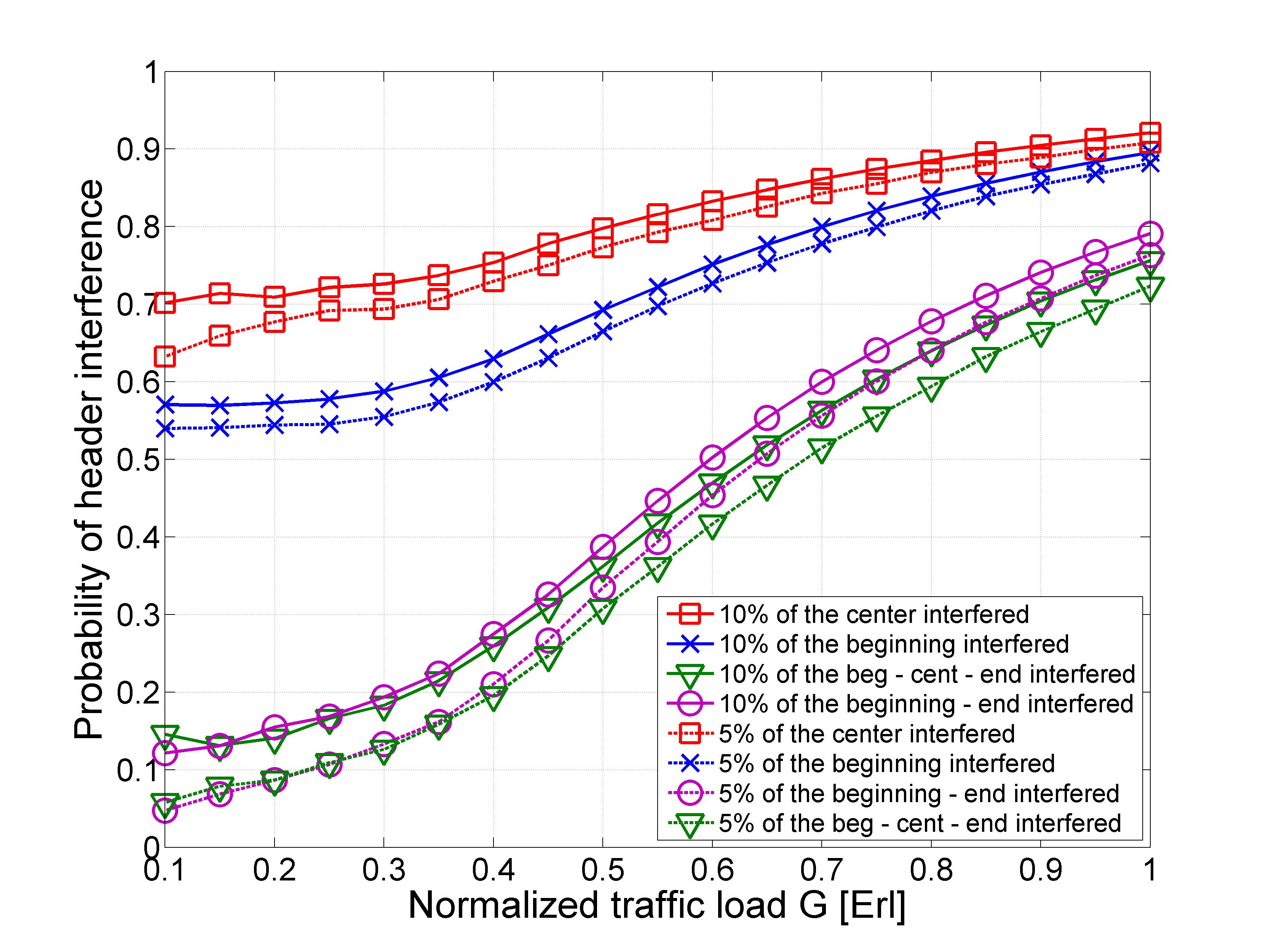
In figure 5 the results for different header positions and different header lengths are provided. Two header lengths are assumed (continuous curves) and (dotted curves). The scenarios with can be seen as a worst case, in fact having a header which occupies more than 10% of a packet is quite inefficient and would be an overhead hardly acceptable, while the choice appears more appealing. As expected the worst case is when the header is placed in the central part of the packet. In this case we have the highest probability that the header symbols face interference, (see figure 4). If we call the probability of interference in the header, in this first case for all the values of offered traffic load for . For low values of , if we decrease the header length to an observable difference in is found which decreases as grows.
When we move the header to the beginning of the packet, the interference probability decreases by more than 10% for both header lengths cases and for w.r.t. to the cases of a header in the center. Also for this second case, the decrease of the header length is beneficial from the probability of header interference point of view. Thanks to the previous section we are ensured that no other positioning of the header can achieve better probability of interference . Moreover, thanks to the symmetry of the symbol interference probability w.r.t. the center of the packet, we know that positioning the header at the end of the packet will achieve the same probability of interference .
Since the information carried by the header on the user replicas position is fundamental for ECRA, it can be thought that replicating this information could improve the reliability. Therefore, two more cases are shown in the figure. The first supposes that the header is placed twice per packet in the beginning and in the end. Here the total overhead due to the header replication is 20% of assuming and 10% of assuming . The second additional case assumes that the header is replicated three times inside each packet: at the beginning, in the center and at the end. In this last case the total header overhead is 30% of assuming and 15% of assuming . The advantage is clear, the header cannot be correctly decoded only if at least one symbol for each of the two or three places where the header is replicated faces interference. Conversely to the other two cases, only one or more symbols interfering in one of the header locations will not prevent the retrieval of the header information and the RP. On the other hand, given a fixed packet length, the replication of the header increases the overhead and decreases the throughput. The simulations of the next section will help to understand the benefits of the header replication. If we consider both cases for , the header interference probability is below 0.2 for and remains below 0.5 until . The difference between the two cases is observable for but very limited in absolute terms (). Moreover, if we consider both the cases for , the header interference probability is lower than 0.2 for and remains under 0.5 until . These results are very promising, especially for the case of header positioning in the beginning and in the end of the packet. The very limited decrease of header interference probability of the three headers case w.r.t the two headers case, cannot counteract the decrease of information sent per packet due to the increase of symbols required by the replication of the header, as will be shown in the next subsection.
IV-B ECRA throughput simulations without perfect packets position knowledge
After the first step where SIC is performed as in CRA, the ECRA protocol tries to create a mix packet from the two user replicas which has the lowest level of interference possible and performs the decoding on it. If it is successful, a second round of SIC is done. In [5], it was assumed that although the remaining packets were not decoded, it was always possible to retrieve the information of their position. Indeed this is not always the case, and here this assumption is removed. Instead, we assume that the information in the RP can be recovered with probability (simulated in figure 5) because represents the probability of no interference in the header(s) where the RP is stored. Therefore with probability we are able to create the mix packet and to try the decoding. Since depends strongly on the simulation parameters, the throughput and PER simulations of ECRA will use the same parameters listed in the previous subsection.
The average packet error rate , is evaluated as:
where is the number of lost packets at the receiver side, and is the number of simulated frames for the corresponding which is . The average throughput is defined as the probability of successful reception of a packet, multiplied by the offered traffic load . The average throughput here is related to the logical throughput, i.e. user packets, whereas the physical throughput would also consider the number of replicas generated per packet. Since the represents the average probability of a packet error, is computed in the following way:
| (6) |
Where is the number of headers per packet. With equation (6) we are taking into consideration the loss of information sent per packet due to the replication of the header. It can be noted that for , e.g. the smaller the packet header w.r.t. to the packet length, the lower is the impact in terms of throughput of the header replication.
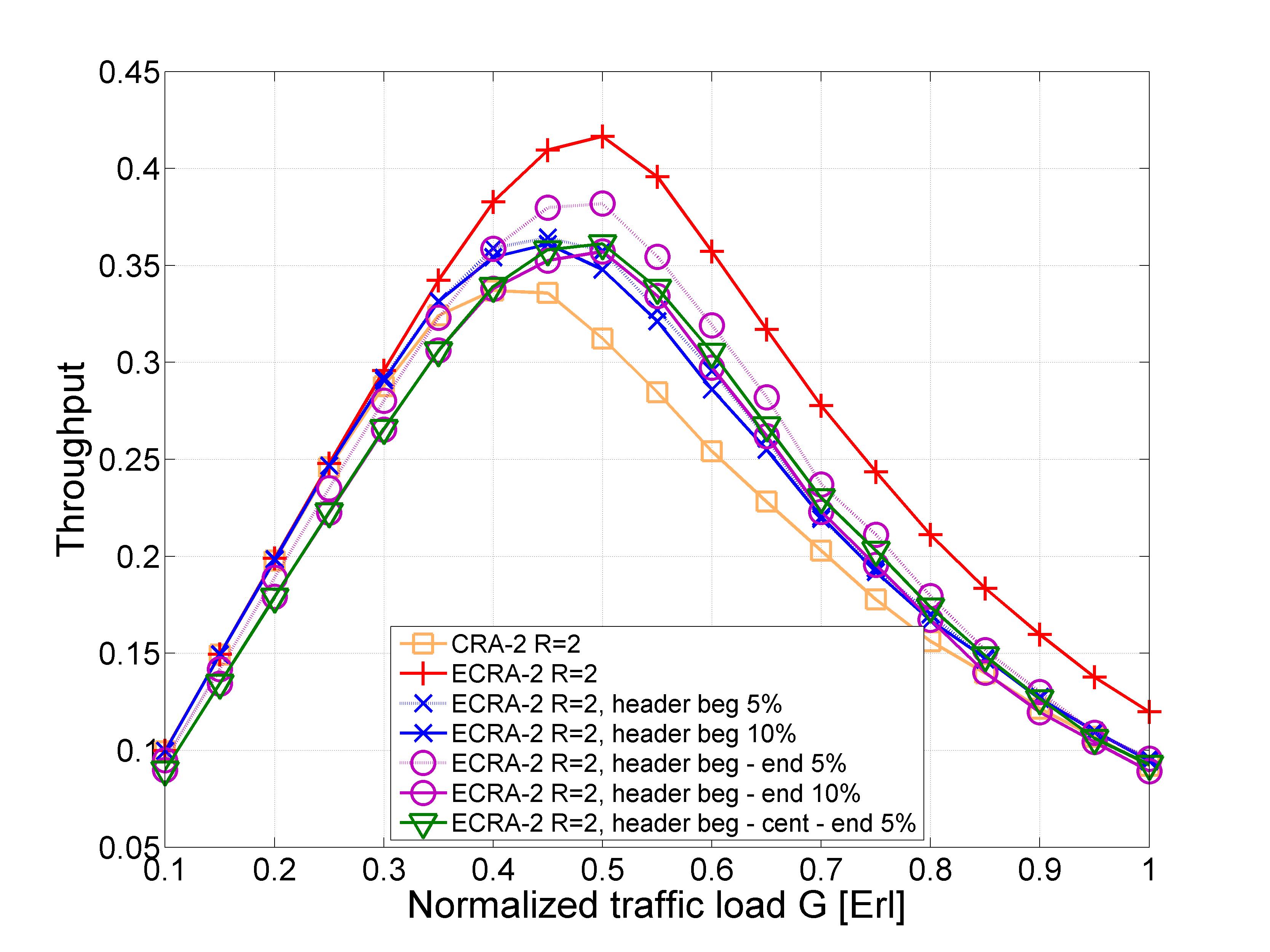
In figure 6 the throughput simulations for different header positions and header lengths are provided. In terms of maximum throughput , the best choice appears positioning the header twice per packet at the beginning and at the end. In this case with the smaller header length the increase of w.r.t. CRA is 13%, while in the case of perfect knowledge of the packet positions the increase is 23%. For all the other header positions and header lengths, the gain of ECRA is reduced to 7%. Please note that when the header is replicated within the packet, the throughput performance for are always slightly worse than the cases with no header replication. This is due to the decrease of information sent per packet.
V Conclusions
In this work, the probability of symbol interference after SIC procedure was mathematically derived for the case of two colliding packets and simulated up to 5 packets colliding. Interestingly, it is shown that regardless of the number of packets involved in the collision, the beginning and the end part of the packet has the lowest probability to face interference. Exploiting this property, the packet header and the RP can be placed in the beginning of the packets. Moreover, it is shown that replicating twice the header in the beginning and in the end of each packet is beneficial also from the ECRA throughput point of view although less information per packet is sent. ECRA throughput simulations are provided when the hypothesis of perfect knowledge of the packets position within the frame is removed. ECRA in the case of header positioning in the beginning and in the end of the packets, showed a throughput gain of 13% w.r.t. CRA if the header has a length of 5% of the packets length. Moreover, it is shown that if the length of the header can be further decreased, a gain up to 23% in the maximum throughput can be reached by ECRA w.r.t. CRA.
References
- [1] G. Choudhury and S. Rappaport, “Diversity aloha–a random access scheme for satellite communications,” Communications, IEEE Transactions on, vol. 31, no. 3, pp. 450 – 457, March 1983.
- [2] E. Casini, R. De Gaudenzi, and O. Herrero, “Contention resolution diversity slotted ALOHA (CRDSA): An enhanced random access scheme for satellite access packet networks,” Wireless Communications, IEEE Transactions on, vol. 6, no. 4, pp. 1408 –1419, April 2007.
- [3] G. Liva, “Graph-based analysis and optimization of contention resolution diversity slotted aloha,” Communications, IEEE Transactions on, vol. 59, no. 2, pp. 477 –487, february 2011.
- [4] C. Kissling, “Performance enhancements for asynchronous random access protocols over satellite,” in Communications (ICC), 2011 IEEE International Conference on, june 2011, pp. 1 –6.
- [5] F. Clazzer and C. Kissling, “Enhanced contention resolution aloha - ECRA,” 9th International ITG Conference on Systems, Communication and Coding, SCC 2013, 2013.
- [6] S. Gollakota and D. Katabi, “Zigzag decoding: Combating hidden terminals in wireless networks,” SIGCOMM’08, pp. 159–170, 2008.