On the nature of large and rogue waves.
Abstract.
In this paper we discuss a model of large and rogue waves in non-necessarily shallow water. We assume that the relevant portion of the flow is restricted to a near-surface layer, assumption which enables us to use the Kadomtsev-Petviashvili equation. The shape and behavior of several types of waves predicted by some singular solutions of the Kadomtsev-Petviashvili equation is compared to the physical waves observed in the ocean.
Key words and phrases:
Rogue waves, freak waves, large wave, Kadomtsev-Petviashvili equation.1991 Mathematics Subject Classification:
35Q35, 35Q51, 76B15.Mikhail Kovalyov
Department of Mathematics, Sungkyunkwan University,
Suwon, Gyeonggi-do, S. Korea
(Communicated by the associate editor name)
1. A very short introduction into the history of rogue waves.
The goal of this paper is to show that the Kadomtsev-Petviashvili equation provides a rough description and classification of large waves and predicts the existence of so-called ”rogue waves”.
Rogue waves (also known as monster waves, freak waves, killer waves, extreme waves, abnormal waves, etc.) are large ocean surface waves that occur far out in sea and appear spontaneously supposedly out of nowhere, even in calm seas. One such rogue wave caused the Ocean Ranger, then the world’s largest offshore platform, to capsize in 1982. Rogue waves could appear in any place of the world ocean, [Divinsky et al.(2004)Divinsky, Levin, Lopatikhin, Pelinovsky & Slyungaev, Earle(1975), Gutshabash & Lavrenov(1986), Irvine & Tilley(1988), Mori et al.(2002)Mori, Liu & Yasuda, Mallory(1974)]. They present a threat even to large ships and ocean liners. Until recently rogue waves were mostly known to exist only through anecdotal evidence provided by those who had encountered them at sea; mariners’ testimonies of rogue waves were often treated with disbelief despite the damages inflicted by such waves on ships. It all changed after the scientific measurement positively confirmed the existence of a large wave at the Draupner platform, in the North Sea on January 1, 1995. Since then numerous accounts of rogue waves have been reported, mostly in media. It’s not just ships and offshore structures that need to worry about rogue waves; the U.S. Navy has expressed concern that some Coast Guard rescue helicopters lost at sea may have been struck by rogue waves [Freeze(2006)]. Can rogue wave shoot up so high as to present a danger to helicopters?
It has been observed that large/rogue waves often appear in sets of more than one, the famous sets of threes known as ”three sisters” are often quoted. According to some accounts three sisters have been observed in Lake Superior. As unbelievable as the stories of rogue waves might have been, even less believable are the stories of the phenomenon known among Russian sailors as ”devyatiy val” (which may be translated as ”the ninth super-wave” or ”the ninth wall of water”) and popularized quite unscientifically by Ivan Aivazovsky in his famous painting of the same name. According to the folklore, rogue waves may appear in groups among which the ninth wave is the strongest and the most devastating, hence the name. Ancient Greeks held similar beliefs only it was the tenth rather then the ninth wave that was the most powerful. Is the ”devyatiy val” just a fiction or may there be a grain of truth in it?
Rogue waves have now been hypothesized as a cause for many unexplained sea losses over the years including the losses over the Bermuda triangle. But can this explanation account for the loss of airplanes? Although not very likely, the aforementioned Cost Guard report certainly leaves the possibility open. As far-fetched as it might be, it is more realistic than the explanations involving ”worm-holes”, extra-terrestrial life-forms or the paranormal.
There seems to be a fad nowadays to refer to any large oceanic/lake wave as a ”rogue wave”. Given the abundance of atmospheric, oceanographic and geological phenomena on Earth it is very unlikely that all large waves have the same cause(s) and exhibit the same behavior. There are currently many models claiming to describe rogue waves, at least some must be fairly successful in describing some type(s) of large waves. Since large waves considerably differ from each other in shape and behavior it is very unlikely that one single model can describe all of them. In this article the term ”rogue waves” is restricted to the large waves which appear seemingly out of nowhere in relatively calm waters, have a relatively short life-span and are localized in a relatively small region of space.
We will show that singular solutions of the Kadomtsev-Petviashvili equation provide a surprisingly good description of the shape of at least some large non-rogue waves and lead to the prediction of the existence of true rogue waves. We will not address the cause of any of these waves. The Kadomtsev-Petviashvili equation is chosen as the simplest nonlinear equation of water waves in many of whose solutions may be computed explicitly. One, of course, should understand that the Kadomtsev-Petviashvili equation may provide only a limited description of the phenomena. It is quite surprising that the Kadomtsev-Petviashvili equation turns out to be so useful as both the singular solutions and the large waves exit on the borderline of applicability of the Kadomtsev-Petviashvili equation derived to describe waves in shallow water. We will address the applicability of the Kadomtsev-Petviashvili equation in the last section.
2. Derivation of the Kadomtsev-Petviashvili equation.
The original derivation of the Kadomtsev-Petviashvili equation was reported in [Kadomtsev B.B.(1970)], since then different derivations based on essentially the same ideas appeared in numerous publications. For the completeness’s sake and because some parts of the derivation will be referred to later on in the paper, we shall reproduce the derivation here. Typically the Kadomtsev-Petviashvili equation is derived for shallow water waves; however, as point 4 of the derivation below shows the validity of the Kadomtsev-Petviashvili equation may be extended to waves in non-shallow water with the vertical component of the motion basically varying only in a near-surface layer. To do so consider the motion of fluid, subject to the following assumptions:
1. The fluid is considered in the region of the three-dimensional space described by
where and is sufficiently small. The set is the bed of the fluid and the function represents the elevation of the free surface above the reference plane at time We shall refer to variables as physical coordinates , to as physical elevation and to as physical variables.
2. The fluid is irrotational, i. e. the velocity vector satisfies for all . Consequently the fluid has a velocity potential , i.e
The assumption of irrotational flow means that there are no non-uniform underlying currents. 3. The fluid is incompressible, i. e. the velocity vector and velocity potential satisfy
4. Typically the derivation of the Kadomtsev-Petviashvili equation is based on the assumption that the bed is impermeable, i.e the velocity and potential satisfy
However, equation (2.4) is also valid if we assume that the flow is horizontal below the plane , i.e for This trivial assumption allows us to extend the derivation to flows in non-shallow water.
5. On the free surface we require that the fluid flows along the free surface without ever leaving the surface, i. e. the vertical component of the velocity satisfies
6. We assume that the density of the fluid is constant, i. e.
7. The fluid is inviscid, i. e. there is no frictions and the only forces present are gravity and pressure. On the free surface the pressure is given where is atmospheric pressure, is surface tension, is the unit normal to and are the reciprocals of the curvature radii. We may assume and use assumptions (2.6) to simplify the last two expressions to and which in turn simplifies the equation for to
8. The potential satisfies the Bernoulli’s equation , where is an arbitrary function. Allowing to absorb the term we may rewrite the restriction of the Bernoulli’s equation to the free surface as
9. The fluid motion is essentially one-dimensional with the main motion occurring along the , the motion and variations along the are smaller than the motion and variations along the we symbolically write it as
For sufficiently small the first approximation is obtained by setting . Equations (2.3), (2.4), (2.5), (2.8) become
We may look for a solution of system (2.10) - (2.13) in the form
and
Substituting (2.15) into (2.10), we obtain equation whose general solution is which upon substitution into (2.15) gives us
Here and are constants of integration which can be determined from boundary conditions (2.11) and (2.12)
Substituting (2.17) into (2.16) we obtain
Boundary condition (2.13) gives us the relationship between and in the form
Solving (2.19) for positive and using Taylor approximation along with which is due to (2.9), we obtain
As the first approximation to we may consider
whose first term satisfies
known as linear Kadomtsev-Petviashvili equation. The nonlinear physical Kadomtsev-Petviashvili equation is obtained by adding to the left hand-side a nonlinear term proportional to based on some physical argument. The derivation of (2.22) is based on the premise that waves are of the form (2.14)-(2.15) and , and are small, i.e. waves (2.14)-(2.15) have long wave length considerably exceeding the depth. Due to this the Kadomtsev-Petviashvili equation is often said to describe long waves in shallow water.
The derivation above is based on the assumption that the solutions of the Kadomtsev-Petviashvili equation are of the form (2.14) - (2.15) which is quite restrictive. We may somewhat generalize the derivation using multi-scale approach by introducing dimensionless coordinates
which transform equations (2.3), (2.4), (2.5), (2.8) into
We look for solutions of system (2.24)-(2.27) in the form
Substituting (2.28) into (2.24)-(2.25) we obtain
Substituting (2.28) into (2.29) - (2.30) and equating to zero the coefficients of we obtain
Equating to zero the coefficient of in (2.32) and using we obtain
Equating the coefficient of in (2.32) to zero and using , as well as (2.34) we obtain
Substituting , , , into equation (2.31) we obtain that the coefficients of and trivially vanish while equating to zero the coefficient of gives us
Differentiation of (2.35) in with the help of (2.34) further gives us
Subtracting (2.36) from (2.37) we obtain
Differentiation of (2.38) in yields, with the help of (2.34),
or in dimensional coordinates
which we shall call physical Kadomtsev-Petviashvili equation. Notice that even if we dropped in (2.27), or, equivalently, assumed that in the derivation of (2.7), would still appear in (2.39).
The change of variables
or equivalently,
turns equation (2.40) into
which is known as the Kadomtsev-Petviashvili equation or simply KP. Notice that the physical Kadomtsev-Petviashvili equation given by (2.40) differs from the Kadom- tsev-Petviashvili equation given by (2.42). It is the physical Kadomtsev-Petviashvili equation (2.40) that describes the physical elevation in terms of physical coordinates ; equation (2.42) describes a nonphysical quantity in terms of variables in the frame of reference moving with velocity in the physical frame of reference . The quantity is the shallow water speed for irrotational travelling waves propagating in water of mean depth , see [Johnson, R. S. (1997)]
Notice that formulas (2.2) and (2.34) imply that for
where, according to (2.2), is just the component of the velocity of the flow. Thus the physical Kadomtsev-Petviashvili equation may be viewed as an equation not only for elevation but also for the component of the velocity of the flow . Moreover, the first two formulas in (2.33) and formula (2.34) imply that for
keeping in mind that due to (2.23).
Formulas (2.43), (2.44) give us the components of the velocity of motion of the fluid not of the profile . Whereas the profile may move in one direction the fluid on the surface may move in another direction.
3. Special solutions of KP and corresponding physical waves.
The simplest solution of KP is a soliton wall solution
where are real constants. Nonlinear superposition of soliton walls is given by
where
are the regular Kronecker symbols, are real constants.
We may determine the velocity of the motion of a single soliton wall by setting which gives us
So velocity is not defined uniquely but up to an additive term proportional to the unit vector .
The components of the velocity of motion of the superposition of two soliton walls satisfy the system of equations
and are uniquely defined provided the determinant of the system is nonzero, i.e. . We cannot attach a meaningful definition of velocity to the motion of nonlinear superposition of three or more soliton walls. The velocity of the soliton wall is not to be confused with the velocity of the flow given by the vector the former is the velocity of motion of the profile while the latter is the velocity of motion of the fluid. The two velocities are not the same. While in a periodic traveling wave with no underlying current the wave profile moves without change of form in one direction, the particles beneath the surface wave move backwards and forwards, [Constantin(2006)]. In contrast to this, for solitary waves all particles move in the direction of wave propagation, having an ascending or descending path depending on their position relative to the wave crest, [Constantin(2007)].
Solutions (3.1), (3.2) have been well studied with references too numerous to mention so we shall skip the discussion of (3.1), (3.2).
One may notice that while the derivation (2.14)-(2.22) of the Kadomtsev-Petviashvili equation starts with the assumption that solutions are of the form (2.14)-(2.15), functions (2.14)-(2.15) themselves are not solutions of KP [Kovalyov & Bica(2005)]. In search for solutions of KP of the form close to (2.14)-(2.15) they arrived at
where are some constants. If the constants are real so is the solution (3.5). Nonlinear superposition of such solutions is of the form
where is an matrix with the entries
where are constants. Change of constants allows us to change the sign in front of while the change for all allows us to change the sign in front of all
Solution (3.5) is singular and approaches as we move towards the singular curve To be physically plausible it needs to be regularized to remove infinities; since there is no clear way to determine what kind of regularization is most suitable we choose an ad-hoc regularization
due to its properties
Conditions (3.7b) assure that the regularization is close to the original function in the domain of validity of KP , whereas conditions (3.7c) remove negative infinity and reduce large amplitudes to make them more physically plausible.
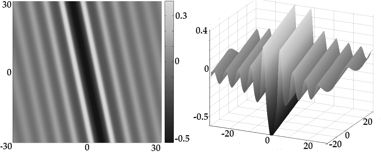
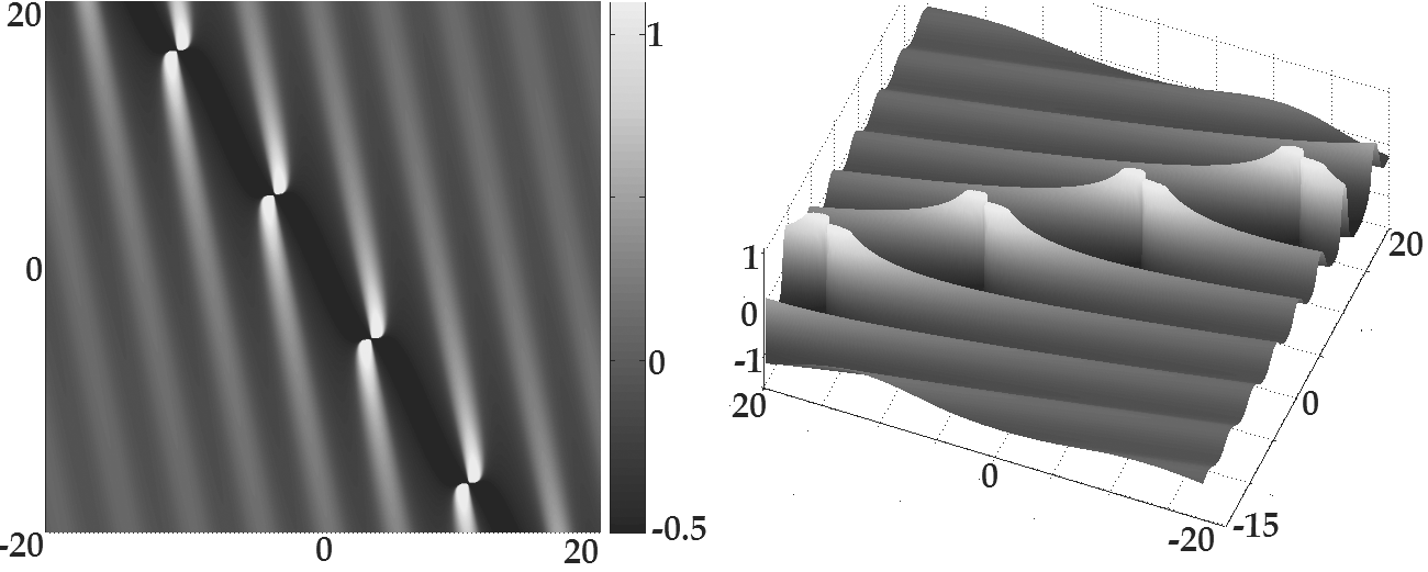
Regularization (3.7) of (3.5) with is shown in Figure 1, while regularization (3.7) of (3.5) with is shown in Figure 2.
We may determine the velocity of motion of the profile given by (3.5) by setting and which give us a system of equations
If the determinant of system (3.8a) is nonzero and the system has a unique solution
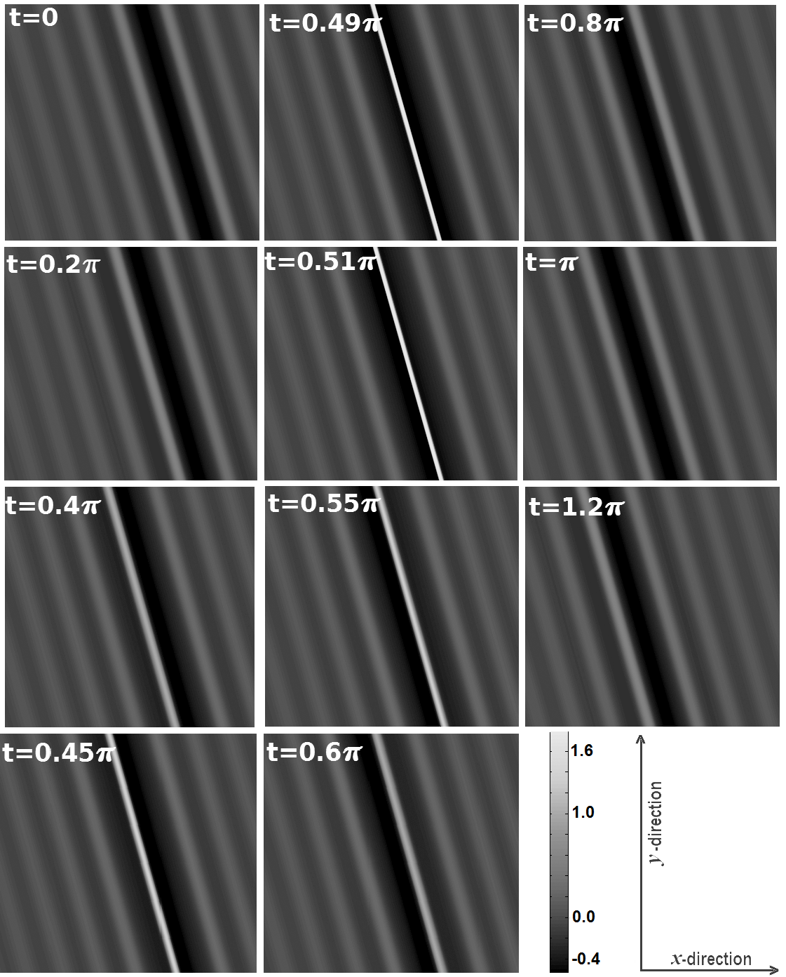
Far away from the singular curve the oscillatory portion of the waves moves in the direction with the speed of which is independent of . The singular curve itself stays within distance from the straight line which moves in the direction of with the speed of bounded for all values of . For profile (3.5) moves in the direction of with the speed of while at the same time oscillating along the same direction. The time evolution of such a wave is shown in Figure 3, it is similar for and
We cannot attach a meaningful definition of velocity to the motion of nonlinear superposition of two or more solutions (3.5). The velocity is not to be confused with the velocity of the flow given by the vector the former is the velocity of motion of the profile while the latter is the velocity of motion of the fluid. The velocity field inside the fluid is is always related to the pressure and at the surface the pressure is constant (hydrostatic), while inside it has a complicated behavior, [Constantin(2010)].
Each such solution consists of two components separated by a singular line. We may retain the component on one side of the singular line and set the function to zero on the other side by taking
or
Sample graphs of (3.9) are shown in Figure 4 for and in Figure 5 for .
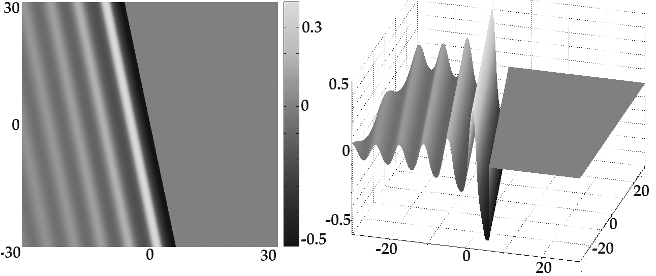
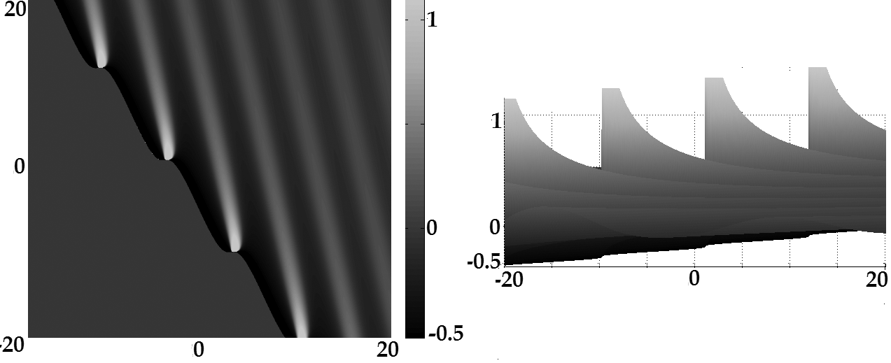
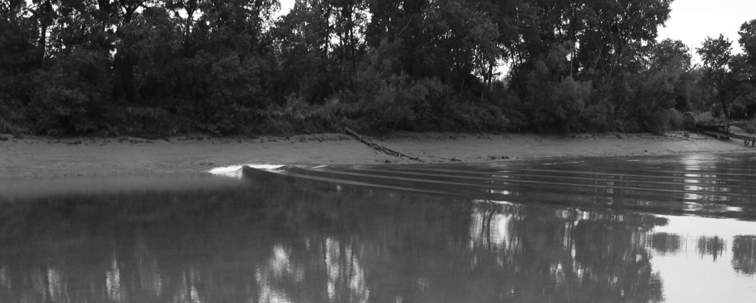
For the obtained function is singular along the line and thus could not be expected to model any physical wave in a neighborhood is some constant, of the singular line. But away from the singular line in the domain function provides a quite good description of undular bores or waves with the advancing strongly-pronounced front followed by a train of well-defined free-surface undulations. Near the singular line has a large negative trough followed by a large positive crest as shown in Figure 4. Formula (2.43) for the physical velocity shows that while water at the crest of the wave continues to move forward, water in the trough moves backwards leading to wave overturning which cannot be described within the framework of KP. Numerous discussions and pictures of undular bores may be found on the Internet, e. g. [Chanson(2010)], one of which is reproduced in Figure 6. Some of the best places to observe undular bores are the French river Seine where the bores form on spring tides and reach some 50 km inland, the Fu-chun River in China, the Amazon River in Brasil, the Severn in England and the Petitcodiac River in New Brunswick, Canada.
An undular bore-like structure was also observed in December 26, 2004 tsunami. As the tsunami passed around the Phi Phi Islands and moved towards Koh Jum island off the cost of Thailand it took undular bore-like form and was photographed by Anders Grawin. The pictures are reproduced in [Constantin(2008)] and [Anders(2004)] with one of them shown in Figure 7.
Several undular bore-like waves are shown in Figure 8 in the image captured by ESA, with some analysis of one of these waves shown in Figure 9.


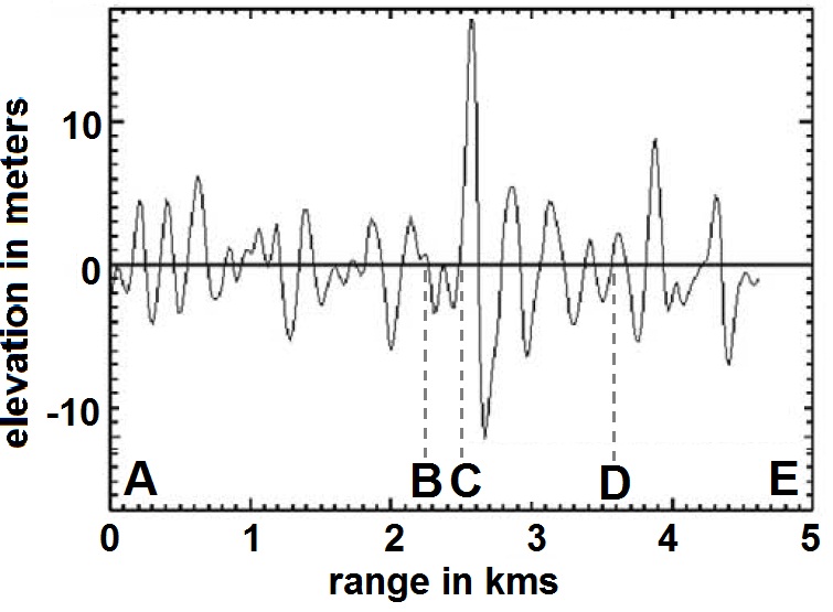
The very existence of the singular line indicates that most of the power of an undular bore is concentrated in the trough at the leading edge rather than at the bore’s crests. The presence of large forces at the leading edge of undular bores is described in [Simpson et al.(2004)Simpson, Fisher & Wiles, Mouaze et al.(2010)Mouaze, Chanson, & Simon, Wolanski et al.(2004)Wolanski, Williams, Spagnol & Chanson]. The account of an undular bore in [Wolanski et al.(2004)Wolanski, Williams, Spagnol & Chanson] as ” unsteady motion … sufficiently energetic to topple moorings that had survived much higher, quasi-steady currents of 1.8 m/s ” also supports the claim that the real power of an undular bore is in its leading trough rather than relatively modest crests even though the leading trough may not be well-pronounced. As follows from (3.5) the leading crest may change its shape.
Often the undular bore-like waves are misinterpreted as trains of solitons with diminishing amplitudes. If that were true, the solitons would be dispersing as the smaller ones travel slower than the taller ones. Yet the undular bore-like structures do not disperse and preserve their shapes for quite a while behaving more like solutions (3.5) than trains of solitons. We refer to solutions (3.5) as ”harmonic breathers”.
Although most undular bores-like waves have the shape shown in Figure 4 with the strongest crest-trough pair leading the wave, there might have been observations of waves with the shape resembling Figure 1 with the strongest crest-trough pair being in the middle rather than in the lead of the wave. According to [Dudley(1998)], the Aleutian tsunami of 1946 produced multi-crest waves with the third or fourth crests being the highest and most violent, and a bore at the Waimea Riverr on Kaua’i is reported to have the sixth crest as the highest and most destructive.
For equation describes a curve rather than a straight line, along the curve function (3.5) is singular and could not be expected to model any physical wave in a neighborhood is some constant, of the singular curve. However, away from the singular curve the function describes the waves observed in the river Seven Ghosts in Sumatra, Indonesia and shown in Figures 10, 11 taken from the video [Rip Curl (2011)].
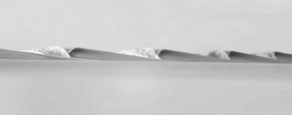

Formula (2.43) for the physical velocity shows that while water in the trough moves backwards, at the points behind the singular curve where the water level is relatively high water continues to move forward, leading to wave overturning but only at some points along the singular curve in agreement with the video taken at the river Seven Ghosts.
Another class of explicit solutions of KP may be obtained by simple formal substitutions
Substitutions (3.10) give us
where are some constants. If the constants are real so is the solution (3.5). Nonlinear superposition of such solutions is of the form
where is an matrix with the entries
where are constants. Change of constants allows us to change the sign in front of while the change for all allows us to change the signs in front of all
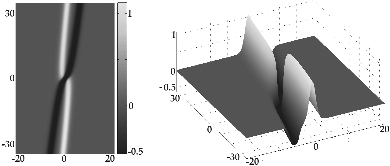
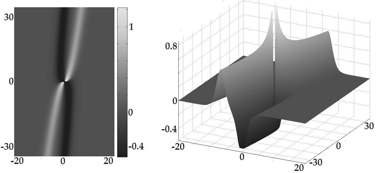
Due to (2.43) the fluid moves to the right whenever such regions are shown in Figures 12, 13 in light shades; the fluid moves to the left whenever , such regions are shown in Figures 12, 13 in dark shades. When for the fluid moving to the right collides with the fluid moving to the left, we obtain a ”crossing” of light and dark lines. The velocity of the motion of the ”crossing” is the same as the velocity of the wave profile and its components may be uniquely determined from the system of equations
obtained from (3.8a) by means of substitutions (3.7). If the determinant of system (3.8a) is nonzero, i. e. , the system has a unique solution
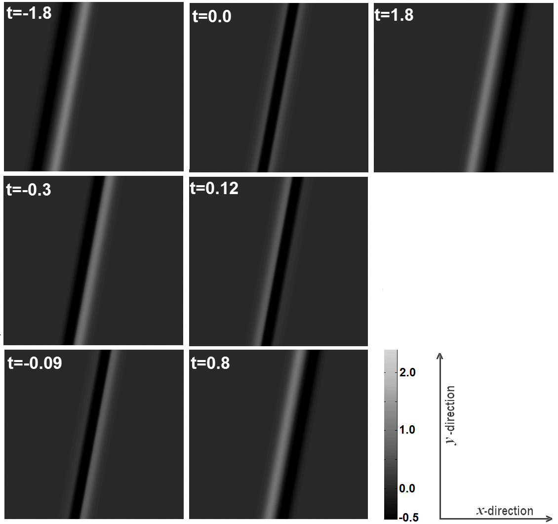
The velocity component is independent of while the component becomes infinite if For the motion of profile (3.11) may be viewed as superposition of two motions: one is the transverse motion in the direction of with the speed of and the other one is the lateral motion of the ”crossing” along the wave in the direction of with velocity . For profile (3.11) moves in the direction of with the speed of while at the same time the crest grows, jumps over the singular line and then disappears, in this case the velocity of the lateral component of the motion becomes infinite. The time evolution of such waves for and is shown in Figures 14 and 15
We cannot attach a meaningful definition of velocity to the motion of nonlinear superposition of two or more solutions (3.11). The velocity is not to be confused with the velocity of the flow given by the vector the former is the velocity of motion of the profile while the latter is the velocity of motion of the fluid.
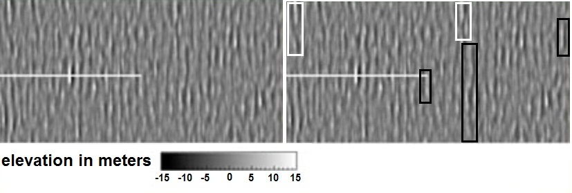
Each of the Figures 12, 13 consists of two long crests preceded or followed by long troughs, each crest-trough pair may be viewed as a separate wave looking somewhat like what is shown in Figures 16, 17. The physical phenomena described by such functions are waves that stretch along an almost straight half-line, with amplitude sharply dropping at the end point and slowly decaying to zero in the other direction, one such wave shown in Figure 18. Much better illustrations may be found at numerous web sites, e.g. [Videos(2010), Riptide(2010)]. An image obtained by ESA from a satellite and reproduced in Figure 19 exhibits several such waves, each is shown by a pair of white and black strips next to each other. One such wave is described in [Graham(2000)] as ” Only the very long swell, of about 15 feet high and probably 600 to 1000 feet long. …We were on the wing of the bridge, with a height of eye of 56 feet, and this wave broke over our heads. …we were diving down off the face of the second of a set of three waves, so the ship just kept falling into the trough, which just kept opening up under us.”
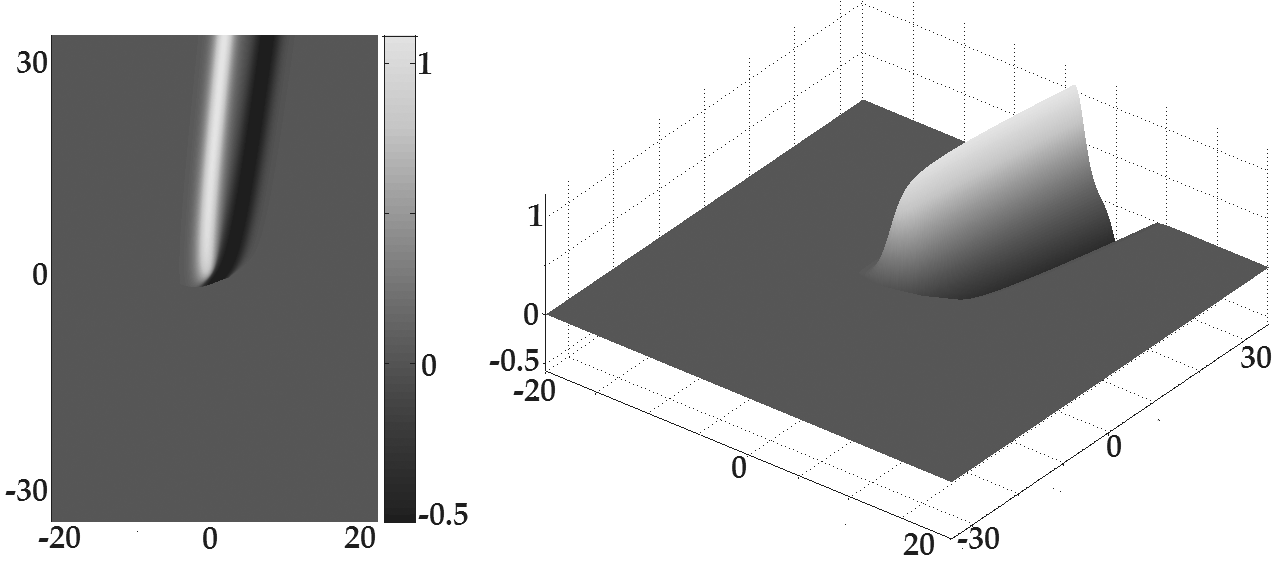
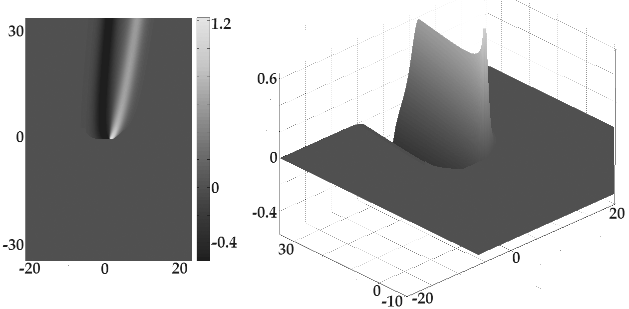

Although some of the literature refer to such waves as ”rogue waves”, we refrain from using the term for this type of waves as typically such waves appear in ”predictable” situations unlike real rogue waves that appear seemingly out of nowhere. While the sharp crest of the wave is clearly visible the trough may not be as apparent.
Another type of a large wave may be obtained by substituting
into (3.11), which gives us
where are real constants, is either a real constant or a real constant . Regularization (3.7) of (3.15) is shown in Figure 20.
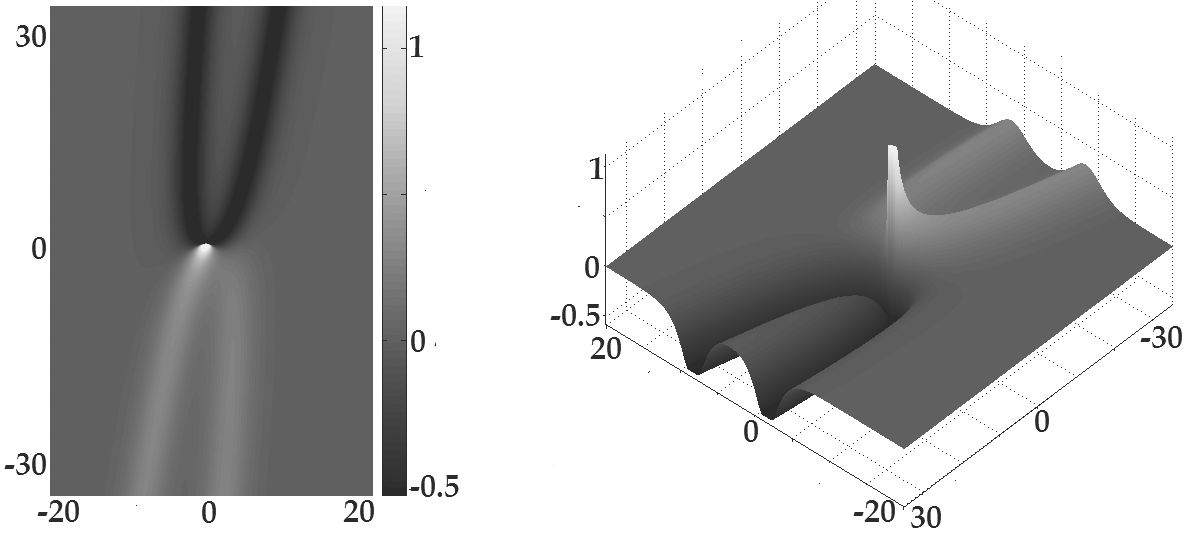
Due to (2.43) the fluid moves to the right whenever such regions are shown in Figure 20 in light shades; the fluid moves to the left whenever , such regions are shown in Figure 20 in dark shades. When the fluid moving to the right collides with the fluid moving to the left, we obtain a ”collision” of light and dark lines. The velocity of motion of the ”collision” is the same as the velocity of the motion of the wave profile, its components may be uniquely determined from the system of equations
obtained from (3.13a) by means of substitutions (3.14). Since the determinant of system (3.16a) is always nonzero, the system has a unique solution
The velocity is finite for all values of The velocity is not to be confused with the velocity of the flow given by the vector the former is the velocity of motion of the profile while the latter is the velocity of motion of the fluid.
Waves of type (3.15) would be extremely unstable, so it would be very unlikely to see one as shown in Figure 20. However the portions shown in Figure 21 should be observable at least for short periods. Indeed, Figures 22-24 show such waves.
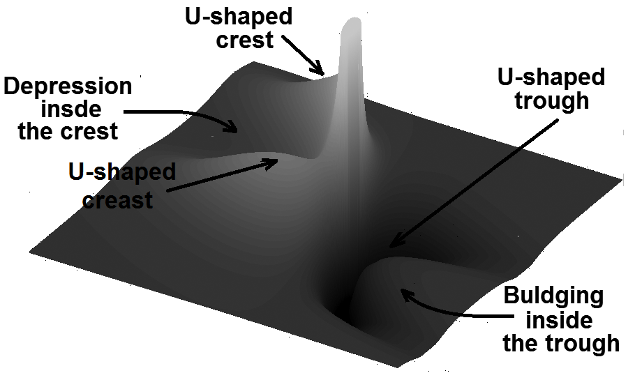
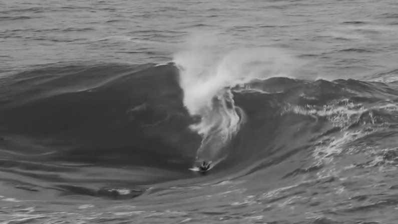
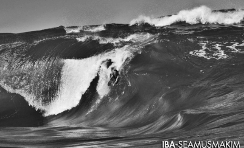
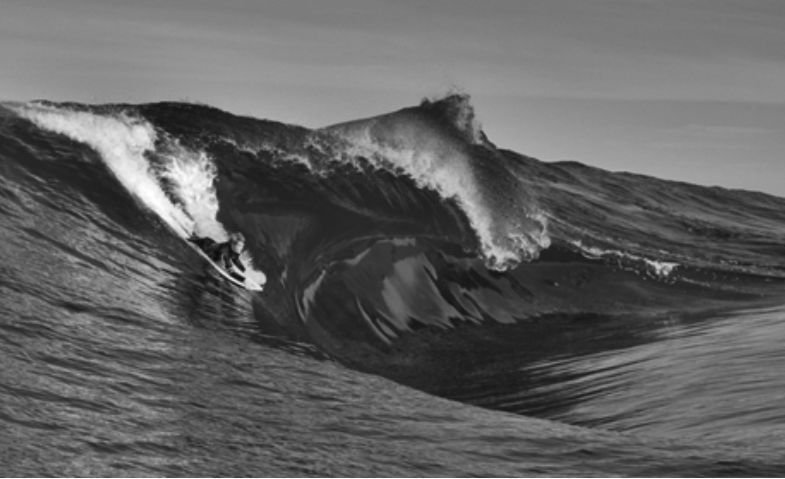
Formula (2.43) implies that the higher up are the points of the fluid the faster they move in the direction ultimately leading to wave overturning which destroys the wave. However, neither solutions (3.11) nor solutions (3.15), (3.18) exhibit wave overturning due to the limitations of KP equations. This limits the applicability and usefulness of solutions (3.11)-(3.15) yet they do describe certain aspects of the corresponding physical waves such as sharp crests, the presence of troughs, the motion as a whole, etc. The life-span of the corresponding physical waves might be relatively long or fairly short depending on how long conditions (2.1)-(2.9) are sustained.
The scaling transformation
equivalent to
transforms each of the solutions of KP considered above into a solution of KP of the same type, the velocity undergoes transformation
Transformation (3.17) allows us to re-scale the graph of the corresponding solution.
4. The true rogue waves.
In the previous section we discussed the use of some singular solutions of KP to model large waves. They may also be used to provide a possible explanation for true rogue waves. Indeed, consider superposition of two waves of type (3.11) given by formulas (3.12). Each wave moves in a corresponding direction with its ”crossing” traveling laterally along the wave as discussed after formula (3.13b). When the ”crossings” of the two waves confluence they produce a drastic short-term jump in amplitude localized in a small region much the same way true rogue waves do. We refer to such a jump as OTIN which is an acronym for One Time INtense big wave/splash/wall of water/etc. The phenomenon is illustrated in Figure 25 where for better visualization we plot ad-hoc re-normalization
rather than Re-normalization (4.1) completely cuts off the values of above and provides a better resolution in the range . The previously-defined re-normalization (3.7) does not cut off any values and allows us to look at all of by using a logarithmic scale yet the very use of the logarithmic scale reduces the resolution. Just like (3.7) re-normalization (4.2) allows us to remove physically unattainable large positive and negative values of given by (3.12). The height of the surface stays relatively low for and while at the time interval a powerful OTIN rises from the water seemingly out of nowhere only to disappears seemingly into oblivion, the amplitude of the OTIN is at least three times the largest amplitude of the waves for . The confluence of the ”crossings” may create a very large OTIN even if the two waves themselves have rather modest amplitudes, making it appear as if the OTIN rises out of nowhere.
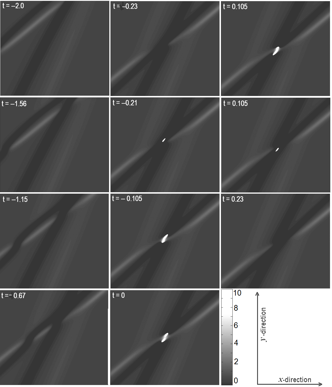
To understand what is happening during the confluence of ”crossings” let us look at Figure 26 depicting three time frames from Figure 25. According to (2.43)-(2.44) the water in the white regions moves to the right and up while at the dark regions it moves to the left and up thus creating undertows at points A and B pumping water from the trough to the crest. At time points A and B merge into one while the two undertows intersect, at the intersection the water has no way to go other than up creating a relatively large but short-lived and spatially localized rogue wave. The formation of an OTIN is somewhat similar to the formation of a rip current. Note that while an OTIN is rising the water moves up very fast resulting in a drop in water pressure under the OTIN, thus a pressure sensor placed placed under the OTIN would show a pressure drop rather than pressure hike.

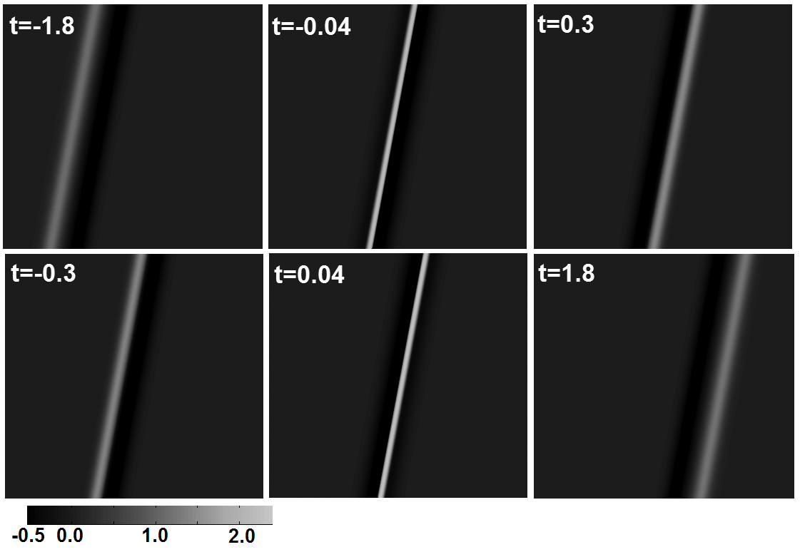
Under certain conditions an OTIN may split into several parts. To demonstrate it consider wave (3.12) with , which differers from the previous example solely by the value of Time evolution of re-normalization (4.1) of this function is shown in Figure 27 in a moving coordinate frame. Notice that the OTIN appears to be the largest and the most powerful in the beginning before it breaks up and in the end after all the parts are recombined together. The event may appear to the crew of a vessel carried by the current as a very powerful wave followed by a few less powerful ones with another powerful wave int he end. Whereas the first one hits the vessel which is still intact and with the relatively fresh crew it may not appear that strong, the last one hits the vessel already heavily pounded with an exhausted crew. It is the last one that would appear to be the most devastating to the crew thus leading to the legends of the ”devyatiy val”.
Figure 27 also shows that the small white spots indicating high elevation cluster in groups of threes, e. g. the lower three white spots in the frame , the upper three white spots in the frame , the upper three white spots the lower three white spots in the frame . Some rogues waves have been reported to appear in groups of threes, e. g. on April 16, 2005 a cruise liner Norwegian Dawn encountered a series of three 21.34 m rogue waves off the coast of Georgia; in March 2012 a cruise liner Louis Majesty encountered a series of three 7.9 m rogue waves between Cartagena and Marseille; there are reports of rogues waves appearing in groups of three on Lake Superior.
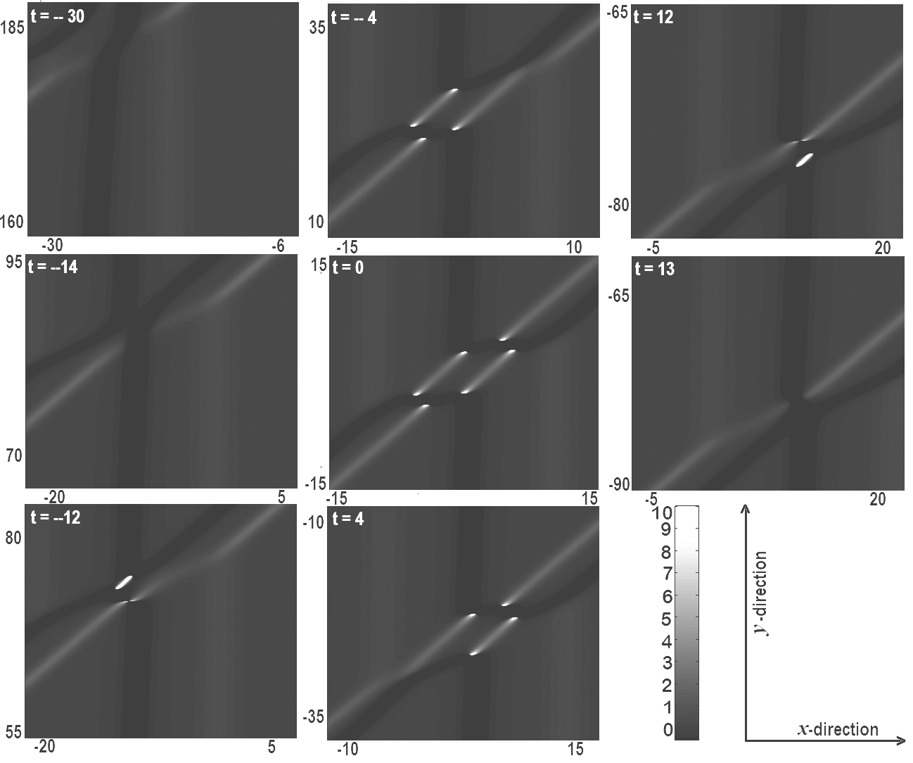
OTINs rise in the regions shown in Figures 25 - 27 in black or close to black shades, these are the regions whose surface is considerably below the sea level and where a lot of underwater traffic takes place, such regions are just giant troughs in the ocean. Since the surface of such a trough is below the sea level, it makes even a modestly tall OTIN to appear considerably taller, e.g. an 4 meter OTIN rising from a trough 3 meters deep appears to the crew of a ship that happens to be in the same trough to be 7 meters tall thus contributing to more drastic perception of the OTIN.
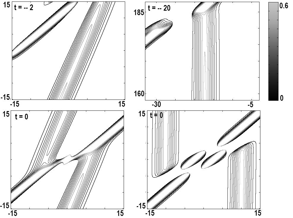
Both graphs have portions somewhat resembling linear waves. Figure 28 provides contour maps of the portions of two frames of Figure 25 (in the first row) and two frames of Figure 27 (in the second row). These waves appear before, after and around the OTINs contributing to the appearance of calm waters and exacerbate the impression of OTINs appearing seemingly out of nowhere.
Figures 25 - 27 illustrate OTINs that arise at the interaction of waves of the type pictured in Figure 12. When the waves pictured in Figure 16 interact the result is not much different. Transformation (3.17) with sufficiently large allows us to re-scale the functions in Figure 25- 27 to reduce the values of before and after the OTIN to very small while making the width of the crests and troughs very large; physical waves corresponding to such functions would be practically invisible before and after the OTIN.
5. Is KP a good model for large and rogue waves?
In this paper we used singular solutions of KP to explain certain observed phenomena, our description and explanation of large and rogue waves considerably differ from other existing models. So the natural question is ”Is it valid?” There are several points to consider.
The first one is whether we can use KP to describe waves in non-shallow water. The Kadomtsev-Petviashvili equation is typically derived for shallow water waves with condition (2.4) interpreted as the plane being the bed of the body of water. In this paper we assume that the body of water is not necessarily shallow not necessarily shallow but the relevant flow is restricted to a near-surface layer below which the vertical component of the flow can be neglected. Such an assumption may not bode well with many a researcher who are used to thinking that any motion on the surface should be felt all the way down to the very bottom, yet anyone with even a minimal SCUBA diving experience can attest to the fact that often even very powerful waves on the surface of the ocean have very little if any at all effect at the depths of even 10-15 meters. What contributes to the disappearance of the flow at greater depths is the viscosity of water small but nevertheless nonzero, internal flows, the motion of plankton and fish, interaction with waves reflected from the floor, etc. In view of all of this, our assumption that the relevant portion of the (not necessarily shallow) flow is restricted to a rather thin near-surface layer with (2.4) on is not unreasonable.
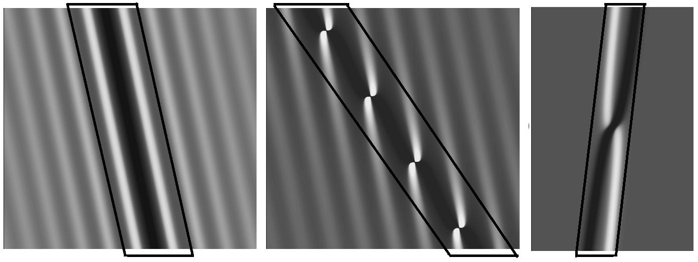
The second point is whether we may use KP to describe waves of relatively large amplitude. Indeed, why would solutions of an equation derived for waves of relatively small amplitude work for waves of a relatively large amplitude? If we look closer at the functions considered such as the ones reproduced in Figure 29 we will see that each such function consists of two parts: one is outside the black parallelogram and the other one is inside. The former is of small amplitude and very well within the regime of KP, it is the latter that contains a crest of large amplitude and a trough extending all the way to taking these functions outside of the regime of KP. However, since the largest portion of the solution shown is outside of the black parallelogram and within the regime of KP it must describe the corresponding physical wave quite well; we may assume therefore that its continuation inside the parallelogram is at least qualitatively similar to the physical wave. Singular solutions are often discarded as nonphysical which may be the case for some, but as shown in this paper the singular solutions discussed in the paper provide a rather good qualitative description of corresponding physical waves. The very existence of the singular curve is somewhat contradictory as we assume the flow is shallow yet the singularity extends all the way down to . Estimate (2.43) allows us to interpret the singularity as an indication of a strong undertow in the region near the singularity, yet since KP is not capable of describing such an undertow the singularities appear. The physical waves corresponding to such solutions do not have crests as high as predicted by the solutions and troughs extending all the way to , but their crests are still relatively tall and troughs are relatively deep. The solutions of KP discussed in this paper are often referred to as ”mathematical caricatures” rather than ”mathematical models” due to the fact that just like regular caricatures they provide rather sketchy description of the phenomena with some features exaggerated and some others suppressed.
Philosophically speaking we may compare the Kadomtsev-Petviashvili equation to a curved mirror shown in Figure 30. A small mosquito flying a few centimeters away from the mirror would see an almost perfect reflection of itself but the image of a large building would be significantly distorted. Yet even distorted, the building’s features could be easily seen and distinguished. Just like the curved mirror the Kadomtsev-Petviashvili equation produces almost a perfect reflection of certain small waves with its soliton solutions; larger waves are described by singular solutions which distort the dimensions but manage to preserve main features of the waves providing a unified albeit very primitive qualitative theory of large and rogue waves predicting the existence of ”crossings” for the waves shown in Figure 12, the existence of bulge inside the trough for the waves shown in Figure 21, the existence of OTINs, the clustering of rogues waves in groups of threes as shown in Figure 27, the appearance of rogue waves seemingly out of nowhere and after a short while disappearance seemingly without a trace, etc. In other words, they show that there is ”a method to the mess” and the same underlying principles are responsible for all these phenomena.

We should also notice that the solutions of KP discussed do not take into account wave overturning/breaking and behave as if wave overturning/breaking does not exist even though formula (2.43) predicts wave overturning/breaking as it implies that the higher points on the crest move faster than the lower ones. To incorporate overturning/breaking into the model KP needs to be replaced with another equation, unfortunately what kind of equation the author does not know yet.
Although it might be tempting to replace the singular solutions discussed in the paper with regular ones expressible in terms of the Riemann function with appropriately chosen parameters, such a replacement might not be very useful. Such a replacement would allow us to remove the singularities at the price of replacing rather simple solutions with much more complicated ones which have essentially the same behavior. The very presence of singular curves allows us to separate wave (3.5) into halves given by (3.9) or the waves shown in Figures 12, 13 into waves shown in Figures 16, 17.
In §3 singular solutions and their superpositions are given by formulas (3.1), (3.2), (3.5), (3.6), (3.11), (3.12), (3.15), yet so far the author has not succeeded in combining these formulas into a single one. The singular solutions discussed here are only the simplest singular solutions of KP, it is possible and very likely that singular solutions not discussed here may shed some light on other physical phenomena.
For completeness sake we mention that there have been previous attempts to model rogue waves using KP. For example, [Biondini(2009), Peterson(2003)] tried to model rogue waves using two-soliton solutions. Their main idea is predicated on the observation that the value of such a solution is considerably larger at the intersection of the solitons and thus may represent a rogue wave. Such attempts, however, were doomed to fail from the start mainly because physical rogue waves appear seemingly out of nowhere and after a short while disappear seemingly without a trace but the two-soliton solutions preserve their shape and move as a whole with velocity given by (3.4). There have been numerous attempts to explain rogue waves in terms of modulation instability for KP, formation of function type of solutions of KP, etc. as well as some properties of solutions of the Korteweg-de Vries equation, the nonlinear Schrodinger equation and several other equations.
Acknowledgments.
The author would like to thank Professor Hubert Chanson for kindly providing his picture of an undular bore; Roger Brooke and Andres Grawin for permission to reproduce the picture of the tsunami of December 26, 2004; Scott McClimont of Rip Curl and the authors for permission to use the frames from the video ”Tip 2 Tip - Seven Ghosts The Teaser” ; Dr. Susanne Lehner and Deutsches Zentrum fur Luft- und Raumfahrt for permission to reproduce Figure 19; Shane Ackerman and Mitch Coslovich for permission to use Figure 22; Mike Maxted for permission to use Figure 24; Seamus Makim for permission to use Figure 22; Tim Lesson and the staff of the Riptide online magazine for help with Figures 22-24. The original pictures were trimmed and turned into black and white by the author of this paper who takes the responsibility for any loss in technical or artistic quality of the pictures.
Although only the work directly related to this paper is referenced and listed in Bibliography, there has been a lot of research in the areas of both singular solutions of integrable equations and rogue waves. The author would like to acknowledge all the work done in both fields and not mentioned here; the references are omitted not out of disrespect but merely due to the policy of more and more journals requiring that only the directly related work be referenced.
Part of the calculations presented in this paper was verified by Mr. Wayne in his MS thesis in the Department of Mathematics of the University of Alberta under the supervision of the author and co-supervision of Dr. Bica.
During the work on the paper the author interviewed numerous fishermen and boatmen on the islands of Cebu and Mactan in the Republic of the Philippines who witnessed or experienced large and rogue waves first hand. The author would like to express his gratitude to all of them even though their names the author has not kept.
References
- [Ackerman(2011)] Ackerman, S., Coslovich M. 2011 Video. In Riptide, November/December, vol. 184, p. 49. Also posted on December 15, 2011, 13:49 at http://www.riptidemag.com.au/.
- [Anders(2004)] Grawin, A. 2004 http://www.kohjumonline.com/anders.html.
- [Biondini(2009)] Biondini, G., Maruno K. Oikawa M. Tsuji H. 2009 Soliton interactions of the Kadomtsev-Petviashvili equation and generation of large-amplitude waves. Stud. Appl. Math. 122, 377–394.
- [Chanson(2010)] Chanson, H. 2010 Gallery of photographs. Also availble at http://staff.civil.uq.edu.au/h.chanson/photo.html#Tidal_bores.
- [Chanson(2011)] Chanson, H., Reungoat D. Simon B. Lubin P. 2011 High-frequency turbulence and suspended sediment concentration measurements in the Garonne River tidal bore . In Estuarine, Coastal and Shelf Science , Issue 2-3, vol. 95, pp. 298–306. Academic Press , Also available at http://espace.library.uq.edu.au/view/UQ:261649.
- [Constantin(2008)] Constantin, A., Johnson R. S. 2008 Propagation of very long water waves, with vorticity, over variable depth, with applications to tsunamis. Fluid Dynamics Research 40, 175-211.
- [Constantin(2006)] Constantin, A. 2006 The trajectories of particles in Stokes waves. Inventiones mathematicae 166, 523-535.
- [Constantin(2007)] Constantin, A., Escher, J. 2007 Particle trajectories in shallow water waves. Bulletin of the American Mathematical Society 44, 423-431.
- [Constantin(2010)] Constantin, A., Strauss, W. 2010 Pressure beneath a Stokes wave. Communications in Pure and Applied Mathematics 63, 533-557.
- [Divinsky et al.(2004)Divinsky, Levin, Lopatikhin, Pelinovsky & Slyungaev] Divinsky, B. V., Levin, B. V., Lopatikhin, L. I., Pelinovsky, E. N. & Slyungaev, A. V. 2004 A freak wave in the Black sea: Observations and simulation. Doklady, Earth Science 395, 438–443.
- [Dudley(1998)] Dudley, W., Lee M. 1998 Tsunami, 2nd edition, page 97. University of Hawaii Press.
- [Earle(1975)] Earle, M. D. 1975 Extreme wave conditions during Hurricane Camille. Journal of Geophysical Research 80, 377–379.
- [Freeze(2006)] Freeze, K. 2006 Monster waves threaten rescue helicopters. In Proceedings of US Naval Institute, December 2006, vol. 132/11/1, pp. 246–247. US Naval Institute, Annapolis, Mariland, Also available at http://www.check-six.com/Coast_Guard/Monster_Waves_Reprint-screen.pdf.
- [Graham(2000)] Graham, D.M. 2000 NOAA vessel swamped by rogue wave. , vol. 284. The quote may also be found at http://hal.archives-ouvertes.fr/docs/00/00/03/52/PDF/Rogue_wave_V1.pdf, bottom of page 4.
- [Gutshabash & Lavrenov(1986)] Gutshabash, Y. S. & Lavrenov, I. V. 1986 Swell transformation in the Cape Agulhas current. Izvestiya, Atmospheric and Oceanic Physics 22, 494–497.
- [Irvine & Tilley(1988)] Irvine, D. E. & Tilley, D. G. 1988 Ocean wave directional spectra and wave-current interaction in the Agulhas from the shuttle imaging radar-B synthetic aperture radar. Journal of Geophysical Research 93, 15389–15401.
- [Johnson, R. S. (1997)] Johnson, R. S. 1988 A modern introduction to the mathematical theory of water waves , Cambridge Univ. Press, Cambridge. qqq10
- [Kadomtsev B.B.(1970)] Kadomtsev B.B., Petviashvili V.I. 1970 On the stability of solitary waves in weakly dispersive media. Sov. Phys. Dokl 15, 539–541.
- [Kovalyov & Bica(2005)] Kovalyov, M. & Bica, I. 2005 Some properties of slowly decaying oscillatory solutions of KP. Chaos, Solitons and Fractals 25/5, 1979–1989.
- [Mallory(1974)] Mallory, K. 1974 Abnormal waves on the south-east of South Africa. Inst. Hydrog. Rev. 51, 89–129.
- [Maxted(2010)] Maxted, M. 2010 Photo. In Riptide, July/August, vol. 176, pp. 88–89. Also posted on June 15, 2010, 13:43 at http://www.riptidemag.com.au/.
- [Mori et al.(2002)Mori, Liu & Yasuda] Mori, N., Liu, P. C. & Yasuda, T. 2002 Analysis of freak wave measurements in the sea of Japan. Ocean Engineering 29, 1399–1414.
- [Mouaze et al.(2010)Mouaze, Chanson, & Simon] Mouaze, D., Chanson, H., & Simon, B. 2010 Field Measurements in the tidal bore of the Selune River in the Bay of Mont Saint Michel (September 2010). In Hydraulic Model Report No. CH81/10,, pp. 246–247. School of Civil Engineering, The University of Queensland, Brisbane, Australia.
- [Peterson(2003)] Peterson, P., Soomere T. Engelbreight J. van Groesen. E. 2003 Soliton interaction as a possible model for extreme waves in shallow water. Nonlin. Proc. Geophys. 10/6, 503–510.
- [Rip Curl (2011)] Rip Curl 2011 Tip 2 Tip - Seven Ghosts. http://www.youtube.com/watch?v=2_vmS-bCoNU, time marks 1:21 and 1:25.
- [Riptide(2010)] Riptide 2010 Riptide Internet journal. http://www.riptidemag.com.au/.
- [Simpson et al.(2004)Simpson, Fisher & Wiles] Simpson, J.H., Fisher, N.R. & Wiles, P. 2004 Reynolds Stress and TKE Production in an Estuary with a Tidal Bore. Estuarine, Coastal and Shelf Science 60/4, 619–627.
-
[Videos(2010)]
Videos 2010
http://www.youtube.com/watch?v=AC2UXYK65Tc&feature=related,
http://www.youtube.com/watch?feature=endscreen&NR=1&v=tmOc0RbMu5k,
http://www.youtube.com/watch?v=gucywjswwZc&feature=related,
http://globalwarming-arclein.blogspot.com/2010/11/6-foot-waves-hit-new-york-in-ancient.html. - [Wolanski et al.(2004)Wolanski, Williams, Spagnol & Chanson] Wolanski, E., Williams, D., Spagnol, S. & Chanson, H. 2004 Undular Tidal Bore Dynamics in the Daly Estuary (DOI: 10.1016/j.ecss.2004.03.001). Estuarine, Coastal and Shelf Science 60/4, 629–636.
Received xxxx 20xx; revised xxxx 20xx.