Quartz Cherenkov Counters for Fast Timing: QUARTIC
Abstract
We have developed particle detectors based on fused silica (quartz) Cherenkov radiators read out with microchannel plate photomultipliers (MCP-PMTs) or silicon photomultipliers (SiPMs) for high precision timing ( 10-15 ps). One application is to measure the times of small angle protons from exclusive reactions, , at the Large Hadron Collider, LHC. They may also be used to measure directional particle fluxes close to external or stored beams. The detectors have small areas (cm2), but need to be active very close ( 4 mm) to the intense LHC beam, and so must be radiation hard and nearly edgeless. We present results of tests of detectors with quartz bars inclined at the Cherenkov angle, and with bars in the form of an “L” (with a 90∘ corner). We also describe a possible design for a fast timing hodoscope with few mm2 elements.
keywords:
Instrumentation for particle accelerators and storage rings - high energy; Trigger detectors; Scintillators1 Introduction
We describe the development of particle detectors with time resolution 15 ps that have the following characteristics: (a) they are edgeless, with active area within about 200 m of the outside (b) they are radiation hard enough to be close to primary beams (c) they have segmentation, allowing independent timing of several particles in a single 1 ns pulse. The main limitation is that they have small active areas, 4 cm2, which is however adequate for our applications. They are compact, and the best time resolution is achieved by having multiple measurements, e.g. four or more modules in-line, giving what we call a time-track. This approach allows monitoring of the resolution and efficiency of each module, and relaxes the requirements on the electronics compared with having a single measurement. The detectors use Cherenkov light in quartz (fused silica) radiators, read out by either microchannel plate photomultipliers (MCP-PMTs) or silicon photomultipliers (SiPMs).
Detectors measuring the time of particles have been used in high energy physics experiments for decades, usually to measure the speed of particles and hence, in conjunction with momentum or (rarely) energy, to determine their mass and hence their identity. Colliding beam experiments typically require large area detectors ( m2) at a few m distance, have time resolutions 100 ps and can separate , K and p in the momentum region 1 GeV/c. Detectors with similarly large areas and better time resolution, by an order of magnitude, are being actively developed [1].
A different use of high resolution timing is to determine the particle path length, especially for ultrarelativistic particles (). This can be used to determine the position of origin of a pair of particles, as in positron emission tomography, PET, where the particles are -rays from annihilation. We report here on the development of detectors with resolution 15 ps to determine the position of origin of a pair of high energy protons, if indeed they came from the same collision. That corresponds to only 4.5 mm of light travel time, and scintillation counters of large dimensions with conventional photomultipliers (PMTs) are excluded. Cherenkov counters have prompt light emission, and MCP-PMTs are inherently faster than conventional PMTs, with transit time spreads (sigma), TTS, (for a single photoelectron) or Single Photon Time Resolution, SPTR, of order 30-50 ps. Available SiPMs have SPTR of order 120 ps, similar to conventional photomultipliers, but there is progress in reducing this. The intrinsic time resolution due to photoelectron statistics with photoelectrons is then , but for a real detector it is also subject to geometry, dimensions and electronics.
In this paper we first give a motivation for our studies, followed by some general background information about Cherenkov radiators and photodetectors. We then discuss three geometries for small quartz Cherenkov counters optimized for fast timimg, followed by some simulations and beam tests. Finally we present a design for a multi-channel bar array suitable for measuring protons very close to the outgoing LHC beams.
1.1 Motivation
This work was largely motivated by proposals [2] to add proton detectors to both ATLAS (called AFP for ATLAS Forward Protons) and CMS (called HPS, for High Precision Spectrometers) at the Large Hadron Collider, LHC, to measure “central exclusive reactions”.For a recent review see Ref.[3]. Examples of such exclusive reactions are and , with no other particles produced. Detecting both protons, and measuring their momenta (after they have traversed LHC magnetic fields), enables many properties of the central state, which is detected in the main central detectors, to be determined [2]. However the cross sections are expected to be very small ( 10 fb), requiring high luminosity , e.g. cm-2 s-1, with 25 interactions per bunch crossing, which has a time spread of 150 ps, every 25 ns. Then the desired 3-fold coincidence events [pXp] have a large background from two-fold pile up [pX][p] or [pp][X], and 3-fold pile up [p][X][p], with obvious notation. The time difference of the two oppositely directed protons’ arrival at far detectors, hundreds of meters down the beam pipes, gives a measure of the collision point, . A resolution on the time difference, t of 15 ps would give mm = 2.25 mm. The vertex position of the central state [X] can usually be reconstructed with m precision, and by matching it to a factor 25 reduction in this pile-up background can be achieved, since the interaction region is much broader ( 50 mm). In combination with other constraints (e.g. no additional tracks on the central vertex, longitudinal momentum conservation, and small transverse momentum, , for the central state) this can make exclusive Higgs, , etc. measurements feasible. Timing resolutions of order t 10 ps are needed for cm-2 s-1 (assuming 2808 bunches, i.e. 25 ns bunch spacing). The time difference measurement between scattered protons was first proposed as a means of reducing pile-up in exclusive interactions at the Tevatron [4, 5].
The required detector area is small ( 4 cm2). Key requirements, in addition to the time resolution, are edgelessness at the level of 100 m on the edge adjacent to the beam, as well as radiation hardness to protons/cm2 [6]. In case there is more than one proton in the acceptance from the same bunch crossing, segmentation is also required. The protons have been deflected out of the beam by the LHC magnets, but at the position (distance along the beam pipe) of the detectors they are displaced by only a few mm, so any inactive area (on one edge) causes a loss in acceptance. We expect a proton flux of about cm-2 per year close to the beam. For both these reasons the photon detector must be placed farther from the beam than the radiator; in addition it can then also be shielded from background radiation. Replacing the photodetectors on a one-year time scale, if necessary, is feasible; they are accessible and relatively inexpensive.
We have tested detectors with various geometries, and here we report on two that can satisfy these stringent requirements. Both are called quartic for QUARtz Timing Cherenkov. The first (“angled-bar quartic”) has quartz bars inclined at the Cherenkov angle with light detected by MCP-PMTs. The second has the quartz bars in the form of an L (L-bar quartic), one bar being the radiator, R, and the other being the light guide, LG. At the end of the LG bar the light is detected by a SiPM. (It could also be detected by an MCP-PMT, although available devices do not have an ideal multi-channel geometry.) This novel geometry works because (a) the protons are very nearly parallel to the radiator bar, and (b) the refractive index of quartz is . With condition (a) all the Cherenkov light is totally internally reflected (TIR) until it reaches the end of the radiator bar, apart from absorption (which is small) and imperfections (on the surface or in the bulk) causing light to be scattered out. With condition (b) the light reflected up the LG bar continues to be totally internally reflected, and is not close to the critical angle. (The angle with respect to the LG bar axis is 90.) It is important that the bars are not aluminized or wrapped, so that close to 100% TIR is maintained, and that they are minimally supported (at a few corner points). We describe this more later, together with geant4 simulations.
Note that the quantity which must be precisely measured is the time difference between the protons at the detectors approximately 480 m, and later 840 m, apart. This requires a reference time signal (“clock”) at each detector with minimal jitter between the left (L) and right (R) detectors, . Reference timing systems developed for the International Linear Collider (ILC) have been designed to yield an r.m.s. jitter 1 ps over similar distances, using RF transmission and a phase-locked loop.
A calibration of the absolute time difference (or ) can be derived from real events of the type , where is a set of particles measured in the central detector.
While the time difference gives , the absolute time, or (minus a constant), would provide another, orthogonal, variable for pile-up rejection if the actual event time were known much better than 150 ps. The existing ATLAS and CMS detectors do not have such capability. It could be made available with large area (and thin) fast timing detectors [1] in a future upgrade, but we do not discuss that here.
A precision track detector, using silicon (or possibly diamond) strips or pixels precedes the timing detectors, giving the position and direction of the protons. quartic detectors are relatively thick; the nuclear interaction length of quartz is 44 cm and the radiation length is 12.3 cm. They should therefore be positioned after the tracking. Interactions in the quartz should not degrade the time measurement significantly (and may even improve it!)
Another possible application of these small, edgeless, fast and radiation hard detectors is to measure the fluxes of particles very close to a circulating, or external, beam. The detectors we have developed should be suitable for such beam condition monitoring; they are also directional, distinguishing “incoming” and “outgoing” particles.
1.2 Cherenkov detectors for timing
Cherenkov light is prompt and therefore ideal for fast timing, although the amount of light is small compared with scintillator. Radiators should be transparent, i.e. with a long absorption length , where is the optical wavelength, preferably into the ultraviolet, 200 nm, where most photons are generated. While gases, liquids and solids are all possible radiators, the number of Cherenkov photons radiated is proportional to ; more completely (for charge Q = 1, and = 1):
where is the fine structure constant.
The light is emitted along the particle’s path in a cone with half angle (Cherenkov radiation angle) given by cos. Solid radiators are much shorter than gases for the same light output, an important consideration when space is limited. Among solid radiators, fused silica, SiO2, or quartz, (ultraviolet grade, UVT) is commonly used, and was our choice for these tests. Its refractive index as a function of wavelength is given in Table 1, together with the light absorption length, and the photon detection efficiency, PDE, of the detectors we used. The quartz bars we used were supplied by Specialty Glass [12].
| Wavelength | Refractive | Absorption | PDE (%) | PDE (%) | |
|---|---|---|---|---|---|
| (nm) | Index | (degrees) | length (cm) | MCP-PMT | SiPM |
| 250 | 1.510 | 48.5 | 95 | 20.6 | 0 |
| 300 | 1.488 | 47.8 | 104 | 19.1 | 5 |
| 350 | 1.475 | 47.3 | 111 | 18.6 | 38 |
| 400 | 1.470 | 47.1 | 120 | 13.8 | 48 |
| 450 | 1.465 | 47.0 | 122 | 14.3 | 50 |
| 500 | 1.462 | 46.8 | 125 | 9.4 | 47 |
| 550 | 1.460 | 46.8 | 128 | 8.2 | 40 |
| 600 | 1.458 | 46.7 | 130 | 7.8 | 30 |
| 650 | 1.456 | 46.6 | 130 | 7.3 | 24 |
| 700 | 1.455 | 46.6 | 130 | 2.0 | 18 |
| 750 | 1.450 | 46.4 | 130 | 0.8 | 13 |
The Cherenkov angle in quartz at 250 nm (750 nm) is 48.5∘ (46.4∘) respectively, see Table. 1. This spans the wavelength range where typical photocathodes are sensitive. We will address chromaticity later, but for simplicity we use = 48∘ when it is not important.
The Nagoya group [13] measured the timing properties of a Cherenkov counter with a quartz radiator in-line with a MCP-PMT at the back. If the particles are parallel to the sides of the radiator bar, all the Cherenkov light that hits the sides is totally internally reflected, as the Cherenkov angle, , exactly matches the total internal reflection angle (defined with respect to the surface, not the normal) 111If the radiator bar is clad or immersed in a medium with the light will not be totally reflected..
The approximate rule for the number of photoelectrons in a typical detector is:
for quartz radiator, which gives 200 photoelectrons for 40 mm. The Nagoya group obtained a time resolution of = 6.2 ps with 3 GeV/c pions ( 1).
1.3 Photodetectors: Microchannel Plate PMTs
Microchannel plate PMTs have a photocathode on a quartz (or similar) window, and photoelectrons generate avalanches in thin ceramic plates traversed by holes (pores) with high electric fields (e.g. 2.5 kV per plate, with two plates giving a gain of 106). The single photon time resolution, SPTR, of the MCP-PMT we used is about 30 ps, and with photoelectrons one can expect a contribution to the time resolution from photoelectron statistics to be ps. We used a PHOTEK PMT240 directly in the test beam as a fast reference time detector in most of our tests; there is enough Cherenkov light generated in the 9 mm quartz window that no additional radiator is needed. The PMT240 itself cannot be used to detect particles close to a beam as it is not edgeless. (Also the MCP-PMT will not survive the high particle fluxes, for reasons of radiation damage and photocathode lifetime.) A potential weakness of MCP-PMTs is that the photocathode can get damaged by positive ion feedback, which limits their life to typically photoelectrons, which may be only weeks in the LHC environment. Developments are underway [14] to extend MCP-PMT lifetimes.
1.4 Photodetectors: Silicon photomultipliers
Silicon photomultipliers, SiPMs, are solid state photon counters comprised of a large number of avalanche photodiodes (APDs) or “pixels” of order 20 m dimensions, with a high gain (up to ) in Geiger mode, with an applied voltage just above the breakdown voltage (about 30V to 70V depending on the type). Each discharged pixel has a recovery time of order 100 ns, but with e.g. 100 photoelectrons per event and thousands of pixels per mm2 this can be acceptable. For the SiPMs the PDE is the product of the quantum efficiency and the fractional area coverage of the APDs. SiPMs are rugged, simple to use and relatively cheap per unit, but at present are only available commercially with effective active areas from 11 mm2 to 3.53.5 mm2. Smaller SiPMs have less capacitance and so are intrinsically faster. The SPTR of typical SiPMs is worse than that of an MCP-PMT, but devices with SPTR 65 ps are becoming available.
2 Quartz bar geometries
2.1 Straight bars, in-line or angled
We studied three quartz bar geometries: (a) short bars (from 6 mm to 30 mm) in line with the beam (“Nagoya” configuration) (b) long bars (up to 150 mm) inclined at the Cherenkov angle (“angled-bar quartic”) (c) L-shaped bars with a radiator bar (30 mm - 40 mm long) and a light-guide bar at 90∘ (“L-bar quartic”). Geometry (a) has very efficient light collection, but can only be used when the photodetector can be in the beam. We used it in our tests as a reference counter (in the beam) and to study some general properties, e.g. longer radiator bars give more light, but the time spread is also longer; how do these interplay? In this “in-line” case, if the radiator bar length is the light emitted at the front of the bar arrives at the PMT later than that emitted at the back (one power of is from the path length and one is from the light speed). For a 40 mm bar this time spread is about 160 ps, so that longer bars, while producing more light, may not improve the time resolution. In addition chromatic dispersion should be considered. While most of the Cherenkov light is blue/UV, that light is also slowest and reaches the photodetector later where it is less useful for timing. Over 10 cm a 200 nm photon lags behind an 800 nm photon by = 100 mm = 32.7 ps, in addition to any path length differences.
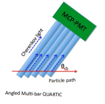
Geometries (b) and (c) have the photodetector remote from the beam, which may be essential for mechanical reasons as well as to be in a low radiation environment. For geometry (b) the radiator bar is long and rotated by an angle so that the photodetector is remote from the beam. A special configuration is for quartz. Then light emitted in a small azimuth (around the proton direction) range arrives directly at the end of the bar; otherwise it takes a longer path with multiple reflections or, if at larger azimuth angles, is refracted out. About 30% arrives at the photodetector. If several bars are to be read out by a single photodetector, it is important that the light from each bar arrives at the photomultiplier at approximately the same time (isochronous design), which occurs with and with the photodetector face normal to the bars, as shown in Fig.1. If the bars are to be read out independently, e.g. with SiPMs which have much smaller area than the MCP-PMTs, this is less important. One could then reduce , but while this increases the thickness of bar traversed and the fraction of light collected, it brings the photodetector closer to the beam, which may not be allowed by mechanical conflicts, radiation damage and background issues.
2.2 The L-bar design
A novel geometry, the L-bar quartic, combines the virtues of having the Cherenkov radiator bar parallel to the beam (with 100% of the radiated light from protons moving parallel to the bar axis being trapped along the bar) and having the photodetector far from the beam. The bar is L-shaped with a 90∘ corner. If the surfaces are perfect, no light is refracted out and it all reaches the end of the light guide, except for the light emitted exactly in the plane perpendicular to the LG bar. Since so that as it is for quartz, the light that passes up the LG bar has an angle with respect to the surface that is , less than the critical angle, and total reflection is maintained. This means that the path length of the light and number of reflections per unit length are all less than in the radiator bar, which help to allow the photodetector to be far from the beam. In addition the blue light path length is less than that of the red light, unlike in the radiator bar. No mirrors are involved, and the surfaces should not be aluminized as then reflection is not total. All the Cherenkov light, except any that is absorbed or scattered out by imperfections in the bulk or surface, reaches the photodetector. Another feature of the L-bar geometry is that it allows segmentation in both and directions, which is not the case for the angled-bar solution.
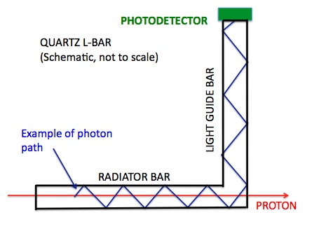
Consider the section of the L-bar shown in Fig.2, with the radiator bar parallel to the z-axis (beam direction) and the light guide bar along the y-axis. For the light rays shown, radiated at angle , the speed of propagation along the z-axis is:
where is the coordinate along the light path. We have = cos , and , so . The speed of light is, in convenient units, 3 mm/10 ps. So for a L = 20 mm radiator bar the time difference between the light emitted at the entrance and at the exit is = 79.4 ps.
After the light has been trapped in the light guide its angle with respect to the bar axis is the complement, i.e. 90, and as the angle in the radiator is , in the light guide it is , and it continues to be totally reflected. Now
and sin. Hence the net light speed along the light guide bar is:
The blue light (larger ) now has a shorter path length, partially compensating for its slower speed. Thus the dispersion is reduced. The ratio of speeds of propagation along the bars is tan , so the effect is modest, about 10%. The fewer reflections per unit length of the radiator bar is another small advantage if TIR is not perfect.
3 Monte Carlo (geant4) simulations
We used geant4 [16] to simulate some of the properties if the in-line-, angled- and L-Bar configurations, to compare with the test beam results, and to aid in the design of a real HPS detector. Cherenkov photons were generated along the proton path with wavelength-dependent refractive index and transmission of fused silica. The emission polar angle is determined by the refractive index , with , and is the azimuthal angle around the beam. The propagation of the optical photons takes into account the surface and bulk properties of the bar (wavelength-dependent photon speed and absorption). In the interval nm about 450 Cherenkov photons are emitted per cm of radiator. We calculated the distribution of the time of arrival of the photons, as a function of , at the MCP-PMT or SiPM. This spectrum was then convoluted with the photon detection efficiency, PDE to simulate the photoelectron time distribution. For each photoelectron a Gaussian time spread with width given by the SPTR was generated and summed, to simulate an output signal. We measured the time when the signal passes 50% of the signal amplitude (from the proton arrival time) to emulate a constant fraction discriminator.
The coupling between the bar and and the photodetector is a potential inefficiency. In the test beam studies grease was used, but it is difficult to simulate correctly. In the simulations we applied an overall efficiency factor to account for both reflectivity and coupling losses to match with test beam data. It is preferable to avoid grease, which can spread to the LG bar; a solid silicon “cookie” can be used.
The surface reflectivity of the bar is an important factor. In a 100 mm LG bar of 33 mm2 cross section one has typically 30 reflections, so if the average internal reflectivity is only 98% only 50% of the light reaches the photodetector. We aim for close to 100% internal reflectivity.
3.1 Simulation of straight bars, in-line or angled
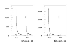
A bar with the dimensions mm3 was used to estimate the timing properties for quartics with straight bars. We simulated the bar both at to the beam and at 90∘, perpendicular, with the beam central. In the L-bar case the perpendicular configuration corresponds to particles through the light guides. The time spectrum of photons arriving on the side with the photodetector is shown in Fig.3. For the perpendicular bar (left plot) the second peak is caused by photons emitted in the opposite direction and reflected from the far side. This does not occur in the angled bar (right plot), as the oppositely directed photons are refracted out of the bar.
We simulated the performance of straight bars inclined at angles to the protons. In the case the light emitted at azimuth in the direction of bar reaches the photodetector with no reflections; light emitted at azimuth up to from the direction of the bar reaches the detector but with longer path lengths. With 15 cm long bars, we set the proton path at different bar angles ; as it decreases the amount of light trapped increases, by a factor 2.5 from 48∘ to 20∘. Ultimately when all the radiated light is trapped. However the time of arrival of the photons has an increasing spread, as the path length of the proton along the bar increases. Furthermore for straight bars the photodetector gets closer to the beam as decreases. The L-bar design overcomes this difficulty.
3.2 L-bar quartic simulation
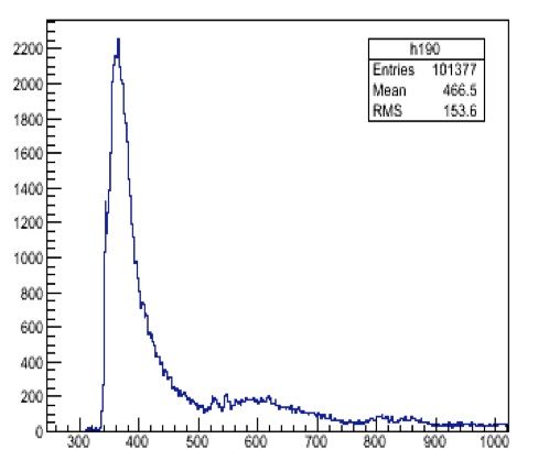
The simulated photons were propagated by total internal reflection, as well as less-than-total, e.g. 99% on average per reflection, to the SiPM. Figure 4 shows the arrival time distribution for photons that produce photoelectrons, from a mm3 radiator bar, with a 40 mm long light guide in the L-bar geometry. The fast leading edge corresponds to photons emitted with azimuth angle close to the LG bar direction (up), and the tail of that pulse corresponds to other angles that have more reflections in the LG. The small later pulse is caused by photons that are not immediately trapped by the LG bar, are reflected back to the entrance of R and return, where they have another chance of being transmitted up the LG. Simulation of radiator bars with both R = 20 mm and R = 40 mm showed the expected shift of the second peak. Photons with arrival times are detected with the probability given by the photon detection efficiency PDE(, giving the number of photoelectrons as a function of time. As previously described we simulated the output pulse, taking = 38 ps for the MCP-PMT and 120 ps for the SiPM. Then the anode signal distribution for each photoelectron is simulated by a unit area Gaussian with 0.5 ns, and these signals added to simulate the output pulse for one proton. We then took the time to be that time when the signal passes 10% (50%) of its peak value. Fig. 5(a) shows the simulated mean pulse height as a function of radiator bar length, assuming 99% reflectivity at all surfaces, and Fig.5(b) shows the estimated time resolution. The LG bar lengths are 80 mm. While the actual resolution depends on some factors that are not well known (e.g. reflectivity and coupling to the photodetector), the qualitative behaviour of a rapid improvement from R = 10 mm to 25 mm, followed by a slower improvement, is as expected.
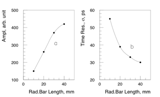
The surface reflectivity of the bars is an important factor. A long light guide bar places the SiPM in a lower radiation field and where it can be better shielded. E.g. with R = 40 mm and LG = 120 mm 100% TIR gives 1500 photons, while an average reflection coefficient of = 0.98 gives only 670 (after about 40 reflections; ). We found by simulation that with = 0.98 the resolution is = 39 ps (30 ps) for R = 20 mm (40 mm). This is very similar to what was found in the beam tests. TIR is even more critical with smaller cross section bars. We will do reflectivity measurements with lasers under different surface conditions to investigate imperfect TIR.
As we expected, the detector simulation shows it to be uniform over the mm2 aperture.
The full transmission of the Cherenkov light along the radiator bar depends on the perfect matching between the Cherenkov angle and the (complement of the) total internal reflection angle. A small angle between the proton direction and the radiator bar axis will allow some light to leak out. We simulated this; e.g. with a radiator bar length of 40 mm and an angle of 1/40 = 25 mrad = 1.4∘ in the plane containing the LG, 20% of the light is lost. In the HPS application the accepted protons have an angular spread of 0.5 mrad, but precise alignment is clearly very important. The directional nature of the L-bar helps, in this application, to have low sensitivity to backgrounds from other directions.
4 Beam tests
We tested prototype quartics in the Fermilab test beam (MTest) with 120 GeV/c protons. The trigger counters and detectors under test were enclosed in a light-tight and RF shielded (with copper sheet) box [8]. The box had light-tight feed-throughs for high voltage and signal cables. A 22 mm2 scintillation counter at the front, viewed by two PMTs in coincidence, provided a trigger and defined the beam. At the back of the box a 55 cm2 counter with a 7 mm diameter central hole, viewed by two PMTs in “OR”, was used as a veto to reject events with upstream interactions. For some of the tests a reference time counter was placed at the back (just upstream of the veto counter); this was a PHOTEK PMT240 MCP-PMT directly in the beam. Cherenkov light in the 9 mm thick quartz window gave a signal of about 35 p.e. with time resolution 8 ps.
We used two types of data acquisition, DAQ. In Phase 1 (DAQ-1), see Ref. [10], with three MCP-PMT detectors under test, the signals were sent through a constant fraction discriminator (ORTEC 9327) and to an ADC to monitor the pulse heights and allow time-slewing corrections to be made. The discriminated pulse was sent to time-to-amplitude converters (TAC, ORTEC 566) with a pair of detectors as input, followed by analog-to-digital converters (ADC, ORTEC 114) read by the on-line computer. The time resolution of the DAQ was measured [10] with a split PiLas laser signal to be (DAQ) ps. The three time differences between the detectors enabled the resolution of each counter to be unfolded. We removed a few percent of the events in the tails of the pulse height distribution due to interactions or pile-up (more than one proton in the same RF bucket), and applied data-driven time slewing corrections (a small linear correction, determined by plotting the time vs pulse height of a signal).
In Phase 2 (DAQ-2), with more channels of SiPM, we used waveform digitizing electronics, DRS4 [17, 9]. This is a 5 giga samples per second (5 GSPS) waveform digitizer, thus giving the pulse shape sampled every 200 ps and allowing off-line fits with a parametrization optimized for timing. We had two DRS-4 modules (boxes) each with four channels. One channel in each box was used for a reference signal from the PMT240 (the output was split with a passive splitter), and the other three for SiPM signals. These SiPM signals were passed through ORTEC VT120 20 amplifiers. We previously published [9] a study of SiPM signals, with a 30 mm long in-line quartz Cherenkov radiator with DRS4 electronics. With Hamamatsu 3 3 mm2 MPPC type S10362-330050C, with 3600 pixels of 50 m, we measured a resolution of = 30 ps. Various algorithms were tried on the waveform to optimize the time resolution. The rise time from 10% to 90% was about 1 ns, i.e. 5 samplings. Good results were obtained by a linear fit to the two points before and after the 50% of pulse-height maximum level, finding the time at which that line crossed the 50% level, and then applying a time-slewing correction. More complete waveform fits were found to be not significantly better. We did not attempt to correct for small differences in the time between successive samples. We measured the intrinsic resolution of the DRS4 channels in situ by splitting the PMT240 signal and sending it to two channels of one box. We found [9] (DRS4) = 6 ps when the time difference between the two signals is very small, but if a delay of 2 ns is put in one channel it rises to (DRS4) = 20 ps.
4.1 Beam tests of straight bars, in-line or angled
We made preliminary studies with single bars, which we describe first.
We demonstrated [8], using quartz bars in-line with a SiPM directly at the back (a), that the time resolution improves with increasing bar length from 6 mm to 30 mm. With a Hamamatsu MPPC (33 mm2) and a 30 mm in-line bar we measured, from the width of the pulse height distribution, about 60 photoelectrons and = 14.5 ps, and = 35 ps with a 6 mm radiator bar. At least over this range the increased light is more important in improving the resolution than the longer pulse is in worsening it.
We made a pair of detectors each with a single 66 mm 80 mm quartz bar coupled to a PMT210 (10 mm diameter photocathode) MCP-PMT with UV transparent optical grease (Dow Corning). We mounted them [8] inclined at = 48∘ on opposite sides of the beam. The beam size (2 mm) would contribute about 10 ps spread in the time difference, but cancels out in the time sum. A PMT240 directly in the beam provided a reference time signal with a resolution = 7.7 ps. We used the DAQ-1 (see above) electronics. After rejecting 10% of events with high pulse height (due to pile-up) and applying a time walk correction (which improved the resolution by 10%), we obtained (after unfolding) = 18 ps for the combined pair.
With a longer, 150 mm bar inclined at 48∘ with the PHOTEK PMT210 we found that, within our measurement uncertainties, the signal was constant with the beam traversing the bar at different distances from 20 mm to 80 mm from the photodetector. The time resolution degraded slightly when the proton distance from the photodetector increased, by about 1 ps/10 mm.
With several bars in-line, all inclined at , and a photodetector normal to the bars as in Fig.1, the Cherenkov light emitted at azimuth in the direction of the photodetector arrives at the same time from all the bars. With a segmented anode MCP-PMT 222The Burle-Photonis 85011 MCP-PMT has an 88 array of 6 mm6mm pads. We used this in earlier studies, and it is an option for the AFP project. This design with a multichannel MCP-PMT has segmentation in (horizontal) but not in (vertical), which is a disadvantage compared with our new baseline design, the L-bar. each bar can be individually read, imposing less stringent requirements on the electronics and potentially gaining a factor in resolution over a single bar. With multiple bars on a single anode MCP-PMT one gains the same factor in photoelectron statistics, but the electronics must be more highly performant.
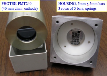
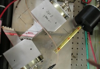
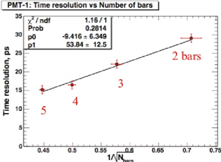
We made a pair of multi-bar detectors with single anode photek [15] PMT240 (2-stage, 40 mm diameter) MCP-PMTs, see Figs 6 and 7. Despite its large photocathode area, the PMT240 has an isochronous anode design; with a pulsed laser scan over the photocathode we verified that the output time is independent of illuminated position to within 2 ps. Each detector had three rows of five 5 mm 5 mm bars in a housing made by electro-erosion of an aluminum block. Each bar was in a square hole with rounded corners such that it touched the housing only at the corners to maintain TIR, and was optically isolated from the other bars.The bars were pushed against the MCP window with springs, and coupled with optical grease. Figs.6 and 7 show the internal arrangement of bars and one layout in the beam (“opposite side” configuration). The beam is () 2 mm wide (determined by the trigger counter) which contributes up to 35 ps to the time spread in a detector. In this configuration the sum of the times (relative to a reference time) in the two detectors is independent of ; on the other hand the time difference is a measure of . We did not have precision tracking to study this correlation. Even with the constant fraction discriminators (CFD) we found [11] a residual correlation between the time difference and the pulse heights, and we applied a linear “time slewing” correction. The corrected distribution was a good fit to a Gaussian distribution with = 23.2 ps. (The TDC was calibrated with a delay cable.) Comparison with a third reference counter showed that the two detectors had the same resolution, 16.00.3 ps each. Combining the pair (“double quartic”) as one would in an experiment then has = 23.2 ps/2 = 11.6 ps. We verified that the time resolution improves with the number of bars as , as shown in Fig.8, showing that the bars contribute about equally; with five bars the number of photoelectrons is 20-25.
4.2 Beam tests of the L-bar quartic
We tested prototypes of the L-bar quartic with 120 GeV/c protons in February 2012 (with DAQ-2). We measured the signals from four bars in-line in 5 GSPS waveform digitisers (DRS4), together with the signal from a faster ( 8 ps resolution) PHOTEK PMT240 behind the test modules.
We made a pair of identical boxes, each containing two R = 40 mm and two R = 30 mm radiator bars, adjacent to each other, and only separated by two 100 m wires, to maintain total internal reflection; there was no wrapping. Bar holders were made that touched the bars only at their corners and only at a few positions. Fig.9 shows the design of an assembled box, with two 30 mm and two 40 mm bars in line.
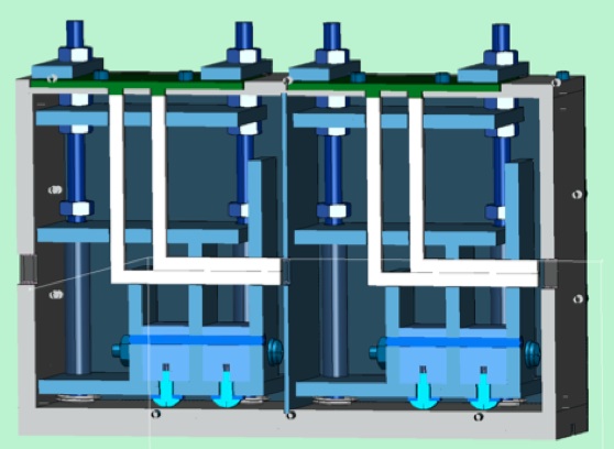
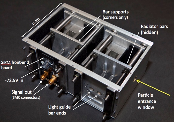
Fig.10 shows a photograph. The interior of the boxes was covered with black felt to absorb any stray light that emerges from the bars. The upstream end of the radiator bars could be blackened to absorb light which is reflected back. We did not do this for these tests, in order to be able to look through both bars in the box (we had small apertures in the front and back plates) to verify alignment and be able to inspect the bars in situ. We made two identical boxes, both for convenience and so that they could be separated in (the beam direction) as an independent check on the time calibration.
The pair of light guide bars, separated by 10 mm in , were coupled with optical grease to Hamamatsu [18] 33 mm2 SiPMs, MPPC S10943-0035. These are mounted on a specially designed circuit board, supplied with -72.5 volts, and the signals were output on SMA connectors. We took data in two configurations, with and without 9.1 pF shaping capacitors in series. In the former case the clipped signal was put through an ORTEC VT120 20 preamplifier. The signals were sent to 8 channels of DRS4 waveform digitisers [9].
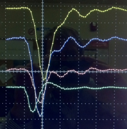
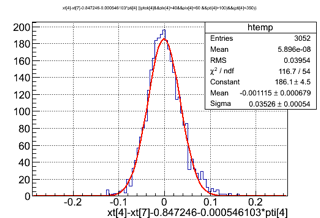
We sent the 22 mm2 beam through four 30 mm (short) radiator bars (with 40 mm light guide bars) and then through four 40 mm (long) bars (43 mm LG bar). Fig.11 shows a typical event; the green (lowest) trace is the PMT240 signal (50 mV/division), and the other traces are the signals from three 30 mm bars, with 2 ns/div and 20 mV per division. The pulses are about 80 mV with a rise time (10% to 90%) of 800 ps. From the spread in pulse heights we estimated the number of photoelectrons to be 80 - 100. We found the signal time from fitting the leading edge (or the full waveform; the difference was small) and correcting for pulse-height slewing. After these corrections, the time differences between the four short bars and the reference PMT240 signal had widths, from Gaussian fits, = 34.9, 39.6, 40.1, and 35.3 ps, so = 37.5 ps. Fig.12 shows one example, with t) = 34.9 ps, and no background or inefficiency. The small spread is an indication of only small differences in the bars, the SiPMs, or their coupling. We found that the DRS4 resolution depends on the time difference between the input signals [9]. After unfolding the PMT and electronics resolution (8 ps and 15 ps respectively) we find (30 mm bar) 33 ps. The time differences between pairs of three different bars in the same DRS4 box were 43.4, 43.9, and 45.2 ps, implying a single bar resolution (30 mm bar) 31 ps, in agreement.
In the proposed application at the LHC [2] we plan four detectors in line. Hence the resolution of the four bars combined would be 16 ps. The SPTR of the SiPM is quoted by Hamamatsu to be 300 ps; giving an expected time resolution for 100 p.e. of 300 ps = 30 ps, in reasonable agrement with the observations. SiPMs with reduced SPTR are becoming available [21]. We checked the time calibration by separating the two detector boxes by 3 cm in the beam direction and observing the 100 ps shift between the L-bar signals. The L-bar geometry has protons that traverse the short bar and cross the light guide of the long bar, and so they also have a signal that is about 10% of the short bar signal, approximately proportional to the proton path length (3 mm). We verified this with the proton beam only through the light guide bars. Protons through the long bar did not pass through the short bar light guides, and we do not see signals there as expected 333Optical coupling between adjacent bars would show up, but is not seen..
We rotated the boxes so that the proton beam passed through the LG bar at 48∘ as in the angled bar studies, but now with the SiPMs, to compare with earlier results using MCP-PMTs. Such angled bars, with SiPMs on the ends, are an alternative geometry to the L-bar. In this test the lengths of the two bars between the proton and the SiPM was only 28 mm and 39 mm. We measured 60 ps in each bar, with about 1/4 the number of photoelectrons. This is much worse that our earlier studies of the angled-bar with an MCP-PMT, the reason being that MCP-PMTs have a much better SPTR than the SiPMs, and extend further in the UV. (We measured SPTR = 45 ps for the PHOTEK240 MCP-PMT, and 120-150 ps for the Hamamatsu MCCP.)
Advantages of the L-bar over the angled bar are a longer radiator path, for a given distance of the SiPM from the beam the light guide bar length is minimized, and in addition -segmentation is possible. It would be possible to combine the L-bar geometry with MCP-PMT readoout, if the pattern of anode pads can match that of the bars. If the photocathode lifetime issue is solved, and cross talk between anode pads444Unlike in the angled-bar quartic, the signals from the different bars do not arrive at the same time. is not large, this could be a good option.
5 A multichannel L-bar array for the LHC: Design considerations
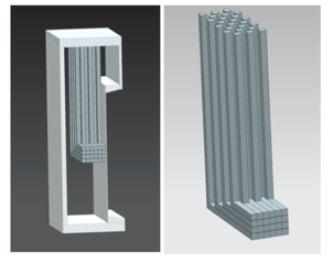
We now present a design for a timing detector using L-bars for the HPS proposal to add very forward tracking and timing detectors to the CMS experiment at the LHC [2]. Fig.13 shows the arrangement of bars in a module. (A similar design would also be suitable for the APF project at ATLAS.) A “module” is a light tight box with a very thin ( 100 m) side wall on the beam side, and blackened interior. The active area is 12 mm (vertically, ) 16 mm (horizontally, ), see Fig.13. (This is an example only; other choices of coverage are equally possible.) One module consists of (46 = 24) independent 33 mm2 bar elements.This allows a time measurement of two or more protons from the same bunch crossing (which has a time spread 150 ps) if they are in different elements. The ends of the light guide bars arrive at an array of SiPMs mounted on a board, together with preamplifiers (and possibly also discriminators). A feature of the L-bar design is that the layout of the SiPMs on the board (in the () plane) reflects the layout of the bars (in the ( plane) but more spread out in . This is shown in the basic board design in Fig.14.
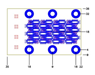
The bars can be held in place, but separated to allow TIR, with grids of fine wires, diameter about 100 m, such that they do not touch and TIR is maintained, in and . The upsteam end of the bars can be made non-reflecting (e.g. with black felt) to reduce the late bounce-back light. They can also be glued in place at the front without significantly affecting the Cherenkov light. The bars have spring contacts on the SiPM faces, with a thin silicon “cookie” for good optical coupling.
The LG can be long enough that the SiPMs can be in shielded enclosures and far enough from the beam that radiation doses are tolerable. Simulations with fluka [19] show that the hadron flux, with kinetic energy above 50 MeV (from collisions) at = 8 cm above the beam plane is only cm fb-1 (one LHC year at high luminosity). A similar flux is expected from beam-gas interactions. Shielding around the SiPMs can reduce the flux of photons and electrons, as well as low energy neutrons 555Neutrons with energies 1 MeV are the main concern, and we are making measurements in situ during LHC runs. A recent study [20] shows only a few percent loss of signal up to 4/cm2, with a rise of dark current which is partially recoverable. Lithiated polyethylene shielding can be installed, if necessary, around the SiPM boards and even around the LG bars without touching them., and only the quartz bars and metal housings are very close to the beam. The main cause of the time spread of the photoelectrons is caused by the length of the radiator bar. The component of the speed of the light along the radiator bar is 0.136 ( = 300nm) - 0.141 ( = 600 nm) mm/ps.
Independent module positioning gives the option of staggering in for better proton position measurement (to combine with the precision silicon tracking). For example if two of the four modules are displaced in by 1.5 mm (half a cell), the quartic measures a track with 450 m, which can help matching to precision silicon pixel or strip track detectors. One maintains four measurements per track except for the 1.5 mm closest to the beam (but that loss can be recovered with two additional cells). Alignment of the radiator bars parallel to the protons is critical (at the level of 10 mrad).
An issue with this design is that particles passing through the shorter bars traverse the light guides of the longer bars at the same , and they will generate light there. This is trapped and reaches the SiPMs. It is only about 10% of the light from the traversed bar and should be readily distinguishable (and one knows the track coordinates). This light can also be used, in the absence of “spoiling tracks”, to help with the timing. Thus for a proton through the shortest bar in Fig.13 we can add the signals from the 33 mm2 light guides behind to the radiator bar signal, reducing the spread in performance between the long and short radiator bars. Another option, if space allows, is to alternate modules with LG bars above and below the beam pipe (this requires a mirror image construction), so protons traverse both long bars and short bars.
These timing detectors will be behind precision silicon tracking, so the hit elements are predetermined, and alignment can be verified. This design has flexibity to adapt to needs. For example the highest track density is close to the LHC beam, and one could have smaller bars, e.g. 1 mm1 mm, in that area, as well as larger bars in the periphery.
6 Further developments
The L-bar quartic gives time measurements when two or more protons from the same bunch crossing are in its acceptance. The design of the test beam modules can be extended to 24 channels with only minor developments. Nevertheless we will continue R&D to improve the time resolution. There are several possibilities. Faster SiPMs with higher photon detection efficiency, and possibly more sensitivity in the UV are becoming available [21]. The SiPMs used in the test were samples from the CMS Hadron Outer (HO) upgrade, and were not optimised for timing. SiPMs from STMicroelectronics (STM) with new P-on-N structure (rather than N-on-P SiPMs, also from STM) show significantly better timing properties [22] 666We thank STMicroelectronics for providing samples.. Tests with a PiLas (Picosecond Injection Laser) showed the photon detection efficiency at = 405 nm, 5 V above breakdown voltage (28 V), to be 43% higher (31.1% cf 21.7%). Also the Single Photoelectron Time Resolution, SPTR, is 174 ps cf 231 ps, i.e. smaller by 25% than for STM N-on-P detectors. Together these improvements lead one to expect that the single bar resolution can be improved from the measured 32 ps to 20 ps, and hence = 10 ps for four modules can be achieved.
6.1 Other radiator materials
Sapphire (Al2O3) is another potential radiator material, with a higher refractive index, ( = 1.70 cf 1.47 at 400 nm) resulting in more Cherenkov photons. The transmission extends down to 250 nm, and sapphire is as radiation hard as quartz. However the time spread over a bar of given radiator length goes like , and the dispersion is higher. geant4 simulations (Section 4) are encouraging, and show a factor 1.9 in the number of detected photons with a 30% improvement in the time resolution. It is therefore a promising alternative to quartz; but laboratory measurements need to be done. There may be even better materials.
6.2 L-bar quartic with MCP-PMT readout
It should be possible to replace the SiPM board, with its 24 independent SiPMs, with a custom designed MCP-PMT, 40 mm 40 mm, with a single photocathode and MCP plates, but with a segmented anode with 24 independent pads. The smaller SPTR and better PDE in the blue/UV should improve the time resolution by a large factor. The Argonne-Chicago-Fermilab team [1] have recently made 20 cm 20 cm MCP plates with the anode divided into strips. Smaller devices with anode pads to match the bars could be developed. If the lifetime, in the harsh LHC conditions, is acceptable, this would be a very interesting development.
6.3 Other comments
If there is longitudinal space one could have more than four modules, gaining as 1/, as they are independent, apart from a common reference time signal which has a negligible jitter. The radiator length was not optimised. The geant4 studies show that the resolution improves almost as over 10 mm 40 mm, simply because of the increase in total light (almost, but not exactly). So in the same total detector length one could choose (say) four bars of 40 mm or eight of 20 mm, and get similar resolutions. The 8-bar option would double the cost for little gain, and is not our baseline. The length of the LG bar has to be determined based on more radiation studies (including dosimeter measurements in the tunnel), and on perfecting TIR on the bar sides. The timing algorithm may be improved, and adapted to the read-out, likely to be an HPTDC (High Precision TDC) [23] with 25 ps resolution.
Smaller area SiPMs, with smaller capacitance, are faster; the L-bar design allows smaller bars in the high density region close to the beam pipe, with larger bars further away.
A set of L-bar modules can provide a prompt signal for triggering events, at level 1 in CMS for detectors at 240 m. The simplest is to make an “OR” of the signals from all the bars in a module, then require, for example, at least three out of four modules to have a signal with fast majority logic, and send a single bit per side to the level 1 trigger. One could also make a more sophisticated fast track trigger, utilizing the spatial information provided by the individual bars. The individual bar bits, after discriminators, are available 10 ns after the passage of the proton. The -coordinate information from each module can be input to a look-up table that can output an approximate proton momentum. This would not be competitive with the silicon tracking, but any reduction of level 1 trigger rates can be important. Time information from the two far detectors can also in principle be used in a fast trigger.
7 Beam monitoring
The L-bar quartic design lends itself naturally to the problem of measuring fluxes of particles near (e.g. a few mm away from) high intensity beams, either in a colliding beam situation (LHC or CLIC) or at an external beam. It can be directional (the end of the bar far from the LG should be made non-reflecting), fast, and can have the SiPM (or another photodetector) remote from the beam and in a shielded enclosure. For a thesis on some relevant studies see Ref. [24]. The detector is designed for single proton detection, but for an intense beam it may be more appropriate to have a gas radiator with a thin mirror at the back to a remote SiPM.
8 Summary
We have developed Cherenkov counters using quartz bar radiators and both MCP-PMT and SiPM readout, designed to measure the time of protons at the LHC very close to the beam, with resolution 10 ps. The area required is only cm2. Our latest design, with a novel L-bar geometry, has = 16 ps, with a path for improvement, and satisfies the other requirements of edgelessness (within about 100 m), sufficient radiation hardness, ability to measure several protons within a bunch (time spread = 150 ps) and to be active every 25 ns (the bunch separation). In this design each proton is measured four times for cross-checks and to improve the resolution. The L-bar quartic detectors can also be used to measure, with good time resolution and directionality, the halo of circulating beams (either inside the vacuum pipe of outside).
9 Acknowledgements
Some of the earlier studies were carried out in collaboration with J.Va’vra (LBNL), A.Brandt (University of Texas at Arlington), J.Pinfold and Shengli Liu (Univ. Alberta). S.Hentschel (Fermilab) designed the L-bar detectors. We thank Jon Howarth (PHOTEK) for loans of MCP-PMTs, and STMicroelectronics for SiPMs. M. Tobin, C. Nicholson and E.A.Wilson (Fermilab summer students) developed geant simulations. We thank Aria Soha for test beam support. We thank Chien-Min Kao for support. We thank the U.S. Department of Energy for support through Fermilab.
References
- [1] H.Frisch et al.,Univ. Chicago, Argonne National Laboratory, Fermilab; Large area picosecond photodetectors project, http://psec.uchichicago.edu/library/index.php.
- [2] M.G.Albrow et al., The FP420 R&D project: Higgs and new physics with forward protons at the LHC, J. Inst. 4 p10001 (2009).
- [3] M.G.Albrow, T.D.Coughlin and J.R.Forshaw, Central Exclusive Particle Production at High Energy Hadron Colliders, Prog. Part. Nucl. Phys. 65 (2010) 149.
- [4] M.G.Albrow and A.Rostovtsev, Searching for the Higgs boson at hadron colliders using the missing mass method, arXiv:hep-ph/0009336 (Sep. 2000).
- [5] M.G.Albrow et al., A Search for the Higgs Boson using very forward tracking detectors with CDF, Letter of Intent to Fermilab PAC, hep-ex/0511057 (Mar. 2001).
- [6] U.Akgun et al., Quartz plate calorimeter as SLHC upgrade to CMS hadronic endcap calorimeters, XIII Int. Conf. Calorimetry in High Energy Physics (CALOR 2008), J.Phys. Conf. Series 160 (2009) 012015.
- [7] A.Ronzhin et al., Tests of timing properties of silicon photomultipliers, Nucl. Instr. Methods A 616 (2010) 38.
- [8] A.Ronzhin et al., Development of a 10 ps level time of flight system in the Fermilab test beam facility, Nucl. Instr. Methods A 623 (2010) 931, and A.Ronzhin et al., FERMILAB-CONF-10-402-E.
- [9] A.Ronzhin et al., Waveform digitization for high resolution timing detectors with silicon photomultipliers, Nucl. Instr. Methods A 668 (2012) 94.
- [10] J. Va’vra et al., Beam test of a time-of-flight detector prototype, Nucl. Instr. Methods A 606 (2009) 404.
- [11] M.Albrow, Acta Phys. Polonica B Proceedings, 4 (2011) 65; arXiv:1104.1438
- [12] Specialty Glass Products, 2885 Terwood Rd., Willow Grove, PA 19090, USA; htp://www.sgpinc.com/
- [13] M.Akatsu et al., MCP-PMT timing property for single photons, Nucl. Instrum. Methods A 528 (2004) 763-775; K.Inami et al., Nucl. Instrum. Methods A 560 (2006) 303.
- [14] T.Jinno et al., Lifetime-extended MCP-PMT, arXiv:1010.1057.
- [15] Photek, http://www.photek.com/
- [16] S.Agostinelli et al., GEANT4: A simulation toolkit, Nucl. Instrum. Methods 506 250 (2003); J.Allison et al., GEANT4 developments and applications, IEEE Trans. Nucl. Sci. 53 270 (2006); http://geant4.cern.ch/
- [17] S.Ritt, Domino Ring Sampler, DRS4 evaluation board manual, drs.web.psi.ch/docs/manual_rev11.pdf
- [18] http://www.hamamatsu.com
- [19] fluka calculations from Luigi Esposito, EN-STI-EET at CERN.
- [20] Yi Qiang et al., Radiation hardness of SiPMs for the JLab Hall D barrel calorimeter, submitted to Nucl. Instrum. Methods A; arXiv:1207.3743
- [21] STMicroelectronics, Catania, 95121, Italy; http://www.st.com/internet/com/home/home.jsp
- [22] M.Mazzillo et al., Enhanced blue-light sensitivity p-on-n silicon photomultipliers fabricated at STMicroelectronics, IEEE Nuclear Science Symposium and Medical Imaging Conference 2011.
- [23] J.Christiansen, HPTDC: High Performance Time to Digital Converter, CERN/EP-MIC.
- [24] Orfanelli S. Styliani, Monte Carlo simulations to estimate the damage potential of electron beam and tests of beam loss detector based on quartz radiator read out by a silicon photomultiplier on CLIC Test Facility 3(CTF3), Diploma Thesis, National Technical University of Athens (Nov. 2011).