Engineered 2D Ising interactions on a trapped-ion quantum simulator with hundreds of spins
Joseph W. Britton1, Brian C. Sawyer1, Adam C. Keith2,3, C.-C. Joseph Wang2, James K. Freericks2, Hermann Uys4, Michael J. Biercuk5, John. J. Bollinger1
1US National Institute of Standards and Technology, Time and Frequency Division, Boulder, CO 80305
2Department of Physics, Georgetown University, Washington, DC 20057
3Department of Physics, North Carolina Stawte University, Raleigh, NC 27695
4National Laser Centre, Council for Scientific and Industrial Research, Pretoria, South Africa
5Centre for Engineered Quantum Systems, School of Physics, The University of Sydney, NSW 2006 Australia
The presence of long-range quantum spin correlations underlies a variety of physical phenomena in condensed matter systems, potentially including high-temperature superconductivity Anderson (1987); Moessner et al. (2000). However, many properties of exotic strongly correlated spin systems (e.g., spin liquids) have proved difficult to study, in part because calculations involving -body entanglement become intractable for as few as particles Sandvik (2010). Feynman divined that a quantum simulator — a special-purpose "analog" processor built using quantum particles (qubits) — would be inherently adept at such problems Feynman (1982); Buluta and Nori (2009). In the context of quantum magnetism, a number of experiments have demonstrated the feasibility of this approach Trotzky et al. (2008); Lin et al. (2009); Jo et al. (2009); Friedenauer et al. (2008); Kim et al. (2010); Simon et al. (2011); Ma et al. (2011); Islam et al. (2011); Lanyon et al. (2011). However, simulations of quantum magnetism allowing controlled, tunable interactions between spins localized on 2D and 3D lattices of more than a few 10’s of qubits have yet to be demonstrated, owing in part to the technical challenge of realizing large-scale qubit arrays. Here we demonstrate a variable-range Ising-type spin-spin interaction on a naturally occurring 2D triangular crystal lattice of hundreds of spin-1/2 particles ( ions stored in a Penning trap), a computationally relevant scale more than an order of magnitude larger than existing experiments. We show that a spin-dependent optical dipole force can produce an antiferromagnetic interaction , where is tunable over ; is the distance between spin pairs. These power-laws correspond physically to infinite-range (), Coulomb-like (), monopole-dipole () and dipole-dipole () couplings. Experimentally, we demonstrate excellent agreement with theory for . This demonstration coupled with the high spin-count, excellent quantum control and low technical complexity of the Penning trap brings within reach simulation of interesting and otherwise computationally intractable problems in quantum magnetism.
A challenge in condensed matter physics is the fact that many quantum-magnetic interactions cannot currently be modeled in a meaningful way. A canonical example is the spin-liquid postulated by Anderson Anderson (1987). He suggested this exotic state would arise in a collection of spin-1/2 particles residing on a triangular lattice and coupled by a nearest-neighbor antiferromagnetic Heisenberg interaction. The spin-liquid’s ground state is massively degenerate, owing to spin frustration, and is expected to exhibit unusual behaviors including phase transitions at zero temperature driven by quantum fluctuations Sachdev (2001). However, despite recent advances Kohno et al. (2007); Varney et al. (2011) a detailed understanding of large-scale frustration in solids remains elusive Moessner et al. (2000); Levi (2007); Helton et al. (2007); Balents (2010).
Atomic physicists have recently entered the fray, providing a bottom-up approach by engineering the relevant spin interactions in quantum simulators Lewenstein et al. (2007); Bloch and Zwerger (2008); Buluta and Nori (2009). The necessary experimental capabilities were first demonstrated in the context of atomic clocks: laser cooling, deterministic spin localization, precise spin-state quantum control, high-fidelity readout, and engineered spin-spin coupling (e.g., Rosenband et al. (2008)). In the domain of quantum magnetism, this tool set permits control of parameters commonly viewed as immutable in natural solid systems, e.g., lattice spacing and geometry, and spin-spin interaction strength and range.
Initial simulations of quantum Ising and Heisenberg interactions with localized spins were done with neutral atoms in optical lattices Trotzky et al. (2008); Simon et al. (2011), atomic ions in Paul traps Friedenauer et al. (2008); Kim et al. (2010); Islam et al. (2011); Lanyon et al. (2011), and photons Ma et al. (2011). This work involved a domain readily calculable on a classical computer: interactions between qubits localized in 1D chains. The move to quantum magnetic interactions on 2D lattices and larger, computationally relevant particle numbers is the crucial next step but can require significant technological development Schmied et al. (2009).
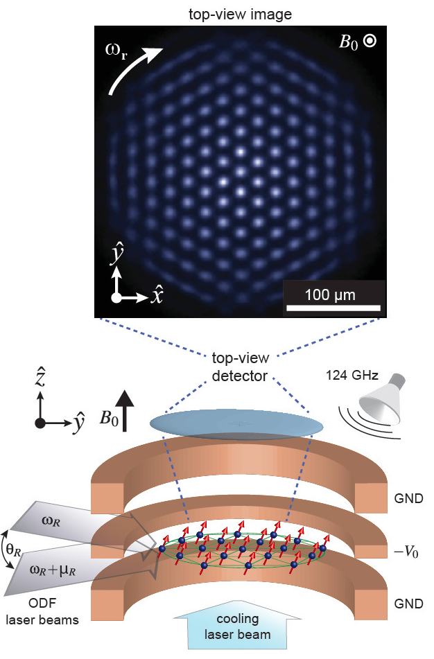
In our Penning trap apparatus, laser-cooled ions naturally form a stable 2D Coulomb crystal on a triangular lattice with spins (Fig. 1). Each ion is spin-1/2 system (qubit) over which we exert high fidelity quantum control Biercuk et al. (2009a). In this paper we demonstrate the use of a spin-dependent optical dipole force (ODF) to engineer a continuously-tunable Ising-type spin-spin coupling . This capability, in tandem with a modified measurement routine (e.g., by more sophisticated processing of images like Fig. 1), is a key advance toward useful simulations of quantum magnetism.
A Penning trap confines ions in a static quadrupolar electric potential (see Methods) and a strong, homogeneous magnetic field (here, Tesla). Axial trapping (along ) is due to the electric field. Ion rotation at frequency (about ) produces a radial restoring potential due to the velocity-dependent Lorentz force (). Tuning the ratio of the axial to radial confinement allows controlled formation of a planar geometry and, after Doppler laser cooling, the formation of a 2D Coulomb crystal on a triangular lattice (see Mitchell et al. (1998) and Methods). We routinely generate crystals with ions, where the valence-electron spin state of each ion serves as a qubit Biercuk et al. (2009a). Following techniques developed in linear (1D) Paul traps Leibfried et al. (2003), spins confined in the same trapping potential are coupled through their shared motional degrees of freedom.
Using well controlled external fields, we engineer spin interactions of the form
| (1) |
where is the -Pauli matrix for ion . We label the qubit spin states and , where is the spin’s projection along the quantizing field, so that and . is an interaction (e.g., ) generated by externally applied microwaves at 124 GHz that couples equally to all spins and permits global rotations (Fig. 1). The interaction describes a general coupling between spins and , distance apart Porras and Cirac (2006); Kim et al. (2009); ( ) is an antiferromagnetic (ferromagnetic) coupling.
We implement using a spatially uniform spin-dependent optical dipole force (ODF) generated by a pair of off-resonant laser beams with difference frequency (see Fig. 1 and Supplementary Information). The ODF couples each ion’s spin to one or more of the transverse (along ) motional modes of the Coulomb crystal by forcing coherent displacements of the ions that in turn modify their Coulomb potential energy through the interaction
| (2) |
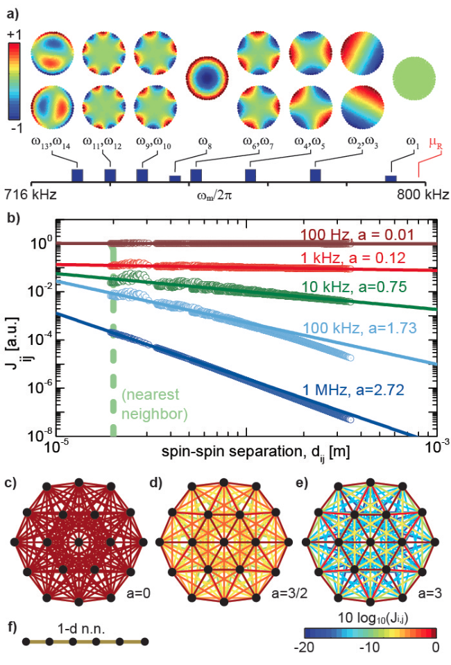
Here is the ODF, is the axial position operator for ion , and are elements of the transverse eigenfunctions at frequencies normalized as Porras and Cirac (2006); Kim et al. (2009). The modes include the center-of-mass mode () as well as an array of higher spatial-frequency modes that may be derived from atomistic calculations (see Fig. 2) and confirmed by experimental measurement Sawyer et al. (2012).
For small coherent displacements, where residual spin-motion entanglement can be neglected (see Kim et al. (2009) and Methods), is equivalent to in Eq. 1: spins and are coupled in proportion to their spin states and and mutual participation in each motional mode . The coupling coefficient is given by Kim et al. (2009)
| (3) |
These pairwise interaction coefficients can be calculated explicitly by use of Eq. 3 and classical calculations of ion motional modes. We find that the range of interaction can be modified by detuning away from the COM mode as discussed in Fig. 2. In the limit kHz, all modes participate equally in the interaction and , as discussed in Porras and Cirac (2006). At intermediate detuning, we find a power-law scaling of the interaction range , where can be tuned . That is, by adjusting the single experimental parameter we can mimic a continuum of physical couplings including important special cases: is infinite-range, is monopole-monopole (Coulomb-like), is monopole-dipole and is dipole-dipole. Note that results in the so-called interaction that gives rise to spin-squeezing and is used in quantum logic gates (see Supplementary Information) Leibfried et al. (2003). In addition, tuning also permits access to both antiferromagnetic (AFM, ) and ferromagnetic (FM, ) couplings Islam et al. (2011).
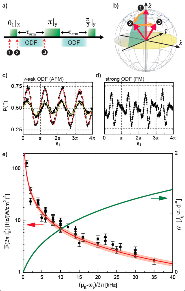
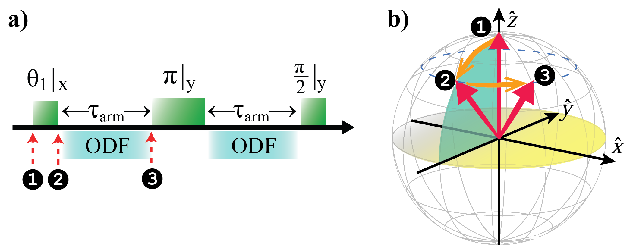
Experimentally, we demonstrate a tunable-range Ising interaction by observing a global spin precession under application of . We compare experimental data with the mean field (MF) prediction that the influence of on spin can be modeled as an excess magnetic field in the -direction due to the remaining spins, (see Supplementary Information). For a general qubit superposition state, gives rise to spin precession about in excess of that expected due to simple Larmor precession. The experiment sequence shown in Fig. 3a measures this excess precession, averaged over all spins in the crystal. At the outset, each spin is prepared in , followed by a rotation about the -axis by an angle . is applied during the arms of a spin-echo; precession coherently adds over both spin-echo intervals. The final -pulse maps precession out of the initial -plane into excursions along (above or below the equatorial plane of the Bloch sphere) that are resolved by projective spin measurement along .
As a function of “tipping-angle” we detect global state-dependent fluorescence ( bright, dark) using a photomultiplier tube. This measurement permits a systematic study of MF-induced spin precession averaged over all particles, . The probability of detecting at the end of the sequence is
| (4) |
and a single-parameter fit to experimental data yields . Decoherence due to spontaneous emission is accounted for by and is fixed by independent measurement of the ODF laser beam intensities (, see Supplementary Information).
In Fig. 3c,d we show representative measurements of excess precession due to for different values of spin coupling strength (determined by ) and interaction duration . The excess spin precession varies periodically with (period ) and larger interaction strength yields greater precession, manifested in our experiment as a larger amplitude modulation of . Data agree with Eq. 4 and allow direct extraction of for given experimental conditions. In Fig. 3e we plot , normalized by ( independently measured), as function of detuning ( ions). Using no free parameters, we find excellent agreement with obtained by averaging over all , where the were calculated by including couplings to all transverse modes (Eq. 3).
The MF interpretation of our benchmarking measurement tolerates only weak spin-spin correlations. Therefore, in the benchmarking regime we apply a weak interaction (, see Supplementary Information). In a quantum simulation, the same interaction is applied at greater power producing quantum spin-spin correlations. In the present configuration of our apparatus, spontaneous emission due to the ODF laser beams ( in Eq. 4) is the dominant source of decoherence. With modest laser powers of /beam and a detuning , we obtain and . The expected spin-squeezing () due to this interaction is , limited by spontaneous emission. The ratio can be reduced ( increased) by a factor of by increasing to , a likely prerequisite for access to the shortest-range, dipole-dipole coupling regime (). At present, geometric constraints limit ; we plan upgrades to our apparatus to permit . We also note that relaxation of the constraint can also reduce .
In summary, this work establishes the suitability of a Penning trap apparatus to pursue quantum simulation in a regime inaccessible to classical computation. Our approach is based on naturally occurring 2D Coulomb (Wigner) crystals with hundreds of ion qubits, a novel experimental system that does not require demanding trap-engineering efforts. Experimentally, we used an optical-dipole force to engineer a tunable-range spin-spin interaction and benchmarked its interaction strength. Excellent agreement is obtained with the predictions of mean field theory and atomistic calculations that predict a power-law antiferromegnetic spin coupling for .
With this work as a foundation, we anticipate a variety of future investigations. For example, simultaneous application of non-commuting interactions and is expected to give rise to quantum phase transitions; may be antiferromagnetic () or ferromagnetic ()). Geometric modifications to our apparatus will permit access to larger and antiferromagnetic dipole-dipole-type couplings (). Improved image processing software will permit direct measurement of spin-spin correlation functions using our existing single-spin-resolving imaging system (Fig. 1).
Methods
In a frame rotating at frequency , the trap potential is
| (5) |
where is the ion charge, is the single-ion mass and . The cyclotron frequency is MHz and the frequency of the ions’ harmonic center-of-mass (COM) motion along is kHz. Ion rotation is precisely controlled with an external rotating quadrupole potential Mitchell et al. (1998). For we set kHz so that the radial confinement is sufficiently weak that a cloud of ions relaxes into a single 2D plane (). Upon Doppler laser cooling the ions’ motional degrees of freedom ( mK) Sawyer et al. (2012), the ions naturally form a 2D Coulomb crystal on a triangular lattice, the geometry that minimizes the energy of their mutual Coulomb potential energy. The crystal has transverse eigenmodes with eigenfunctions ; the COM mode is the highest frequency mode (see Fig. 2).
The spin-dependent ODF is generated by a pair of off-resonance laser beams with angular separation and difference frequency (see Fig. 1). The result is a traveling 1D optical lattice of wavelength whose wavefronts propagate along , traversing the ion crystal at frequency . Alignment of is crucial for proper spin-spin coupling (see Supplementary Information). The lattice’s polarization gradient induces a differential AC Stark shift on the qubit states (a spin-dependent force). We choose operating conditions that give , where . For reference, if the single-beam intensity at the ions is , we obtain N.
Small coherent displacements that produce negligible spin-motion entanglement (as required by Eq. 3) are obtained for detunings satisfying
| (6) |
This is a more stringent criterion than that used by others Kim et al. (2009); Islam et al. (2011) as it includes an additional to account for a typical distribution of composite spin states. Moreover, we also include a correction factor for finite temperature .
Acknowledgments
This work was supported by the DARPA OLE programme and NIST. A.C.K. was supported by the NSF under grant number DMR-1004268. B.C.S. is supported by an NRC fellowship funded by NIST. J.K.F. was supported by the McDevitt endowment bequest at Georgetown University. M.J.B. and J.J.B. acknowledge partial support from the Australian Research Council Center of Excellence for Engineered Quantum Systems CE110001013. We thank F. Da Silva, R. Jordens, D. Leibfried, A. O’Brien, R. Scalettar and A. M. Rey for discussions.
Distribution Information
This manuscript is a contribution of the US National Institute of Standards and Technology and is not subject to US copyright. Correspondence and requests for materials should be addressed to J.W.B. (joe.britton@gmail.com). This version of the manuscript was generated by J.W.B. on April 25, 2012.
Supplementary Information
A review of ion confinement in Penning traps and discussion of a variety of equilibrium states, including 2D Coulomb crystals (ionic Wigner crystals), can be found in Brewer et al. (1988); Mitchell et al. (1998); Dubin and O Neil (1999). A number of authors have theoretically analyzed and discussed the prospects of using 2D Coulomb crystals for quantum information and computation Porras and Cirac (2004, 2006); Buluta et al. (2008); Taylor and Calarco (2008); Zou et al. (2010); Baltrusch et al. (2011). The engineered Ising interaction, which we report here, builds on our previous experimental work using 2D Coulomb crystals for high-fidelity quantum control Biercuk et al. (2009b, a, c); Uys et al. (2009, 2010). Below we discuss some details of this new capability.
I Spin initialization, control, and measurement
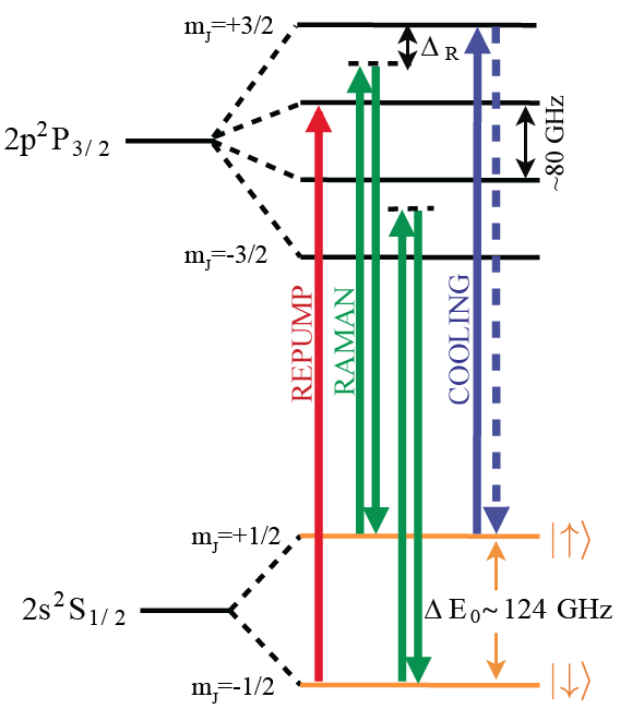
Reference Biercuk et al. (2009a) gives a detailed discussion of our spin initialization, control, and measurement capabilities with planar ion arrays in Penning traps. Here we briefly summarize some of that discussion, emphasizing aspects relevant for the measurements reported here. Figure 4 shows the relevant energy levels. We use the valence electron spin states parallel and antiparallel to the applied magnetic field of the Penning trap as the two-level system or qubit. In the T magnetic field of the trap, these levels are split by approximately GHz. The nucleus has spin . However, we optically pump the nuclear spin to the level Itano and Wineland (1981), where it remains throughout the duration of an experiment. The ions are Doppler laser-cooled to a temperature mK Sawyer et al. (2012) by a MHz linewidth, nm laser tuned approximately 10 MHz below the cycling transition. Spins in the state are efficiently optically pumped to the state by a laser tuned to the transition. The repump beam and the main Doppler laser cooling beam are directed along the magnetic field (-axis). Powers are a few milli-Watt with laser beam waists of mm. In addition, a weak Doppler laser cooling beam (m waist) directed perpendicularly to the -axis directly Doppler cools the perpendicular degrees of freedom. A typical experimental cycle starts with ms to ms of combined Doppler laser cooling and repumping. The repump laser remains on for another ms after the Doppler cooling laser is turned off. The fidelity of the state preparation is estimated to be very high () Biercuk et al. (2009a).
Low-phase-noise microwave radiation at 124 GHz is used to rotate the spins through the magnetic dipole interaction , where is the applied microwave field (predominantly perpendicular to ), is the electron g-factor, and is the Bohr magnetron. The fidelity of a -pulse was measured to be greater than in a random benchmarking experiment Biercuk et al. (2009a). The microwave source consisted of an agile GHz source followed by an amplifier multiplier chain with 150 mW output power at . The GHz source is obtained by mixing, with a single-side-band mixer, the output of a 15.2 GHz dielectric resonator oscillator (DRO) with the output of a MHz direct digital synthesizer (DDS) that is under field programmable gate array (FPGA) control. On/off switching of the GHz microwaves is done at GHz before the amplifier multiplier chain. The microwaves are transported to the ions down the bore of the magnet with a rigid waveguide and directed onto the ions with a horn located between the ring and endcap electrodes of the trap. With this arrangement the microwave hardware does not block optical access along the magnetic field axis, enabling imaging of the ion resonance fluorescence scattered along the magnetic field (top-view image — see III). We obtain -pulses of s duration with the 150 mW output power of the amplifier multiplier chain and the setup described here. The measured spin-echo coherence duration () is ms.
At the end of an experimental sequence we turn on the Doppler cooling laser and make a projective measurement of the ion spin state through state-dependent resonance fluorescence. With the Doppler cooling laser on, an ion in the state scatters photons/s while an ion in is dark. For the spin precession measurements reported here we performed a global spin-state detection. Specifically we detected, with light collection and a photomultiplier tube, the resonance fluorescence from all the ions in a direction perpendicular to the magnetic field (the side-view). For detection periods of ms the detection fidelity is high, typically limited by quantum projection noise. Here we used short detection periods of , from which we would detect photon for each bright state . Typically, each experiment was repeated times and averaged, resulting in a few percent uncertainty due to shot noise in the measurement of .
The spin-precession signal used to benchmark spin-spin coupling in the manuscript relied on a global spin-state measurement via side-view fluorescence collected on a photo-multiplier tube. In the future, we anticipate that time-resolved top-view images such as that shown in Fig. 1 will be used to obtain the spin state of individual ions. As discussed in the manuscript, ion crystal rotation at is phase-locked locked to an external oscillator. We use an imaging photomultiplier tube to record for each photon. Rotating-frame images are generated computationally given and , a technique established in 2001 Mitchell et al. (2001). In linear Paul trap experiments, determination of ion spin-state is possible with as few as photons/ion Itano and Leibfried (1998). At present we await the arrival of a new detector system capable of a detection rate of Hz. We anticipate this will enable high-fidelity spin-state measurement of a -ion crystal in ms. From a suite of identical experiments, the spin-spin correlation function can be computed. We believe that our ability to resolve single ions, even in the presence of rotation at indicates a path forward in performing individually resolved measurements of fluorescence correlations between ions.
Previous measurements have elucidated some of the possible limiting mechanisms. For instance, the stability of crystal orientation in the rotating frame was studied for spherical crystals of ions. In these experiments the orientation was observed to precess uniformly for durations of s, then suddenly slip by a large angle before again resuming slow precession Mitchell et al. (2001). This “stick-slip” motion can be followed and easily corrected. Figure 1a of the manuscript was generated from s of integration after stick-slip corrections. Other potential issues include ion loss and background gas collisions. As the trap depth is eV, background gas collisions do not result ion loss. Collisions with background hydrogen generate (1 per 6 minutes for ions) which collect at the crystal perimeter due to centrifugal separation. These effects do not appear to limit top-view imaging fidelity, as demonstrated in Fig. 1a of the manuscript.
II Optical-dipole-force laser settings
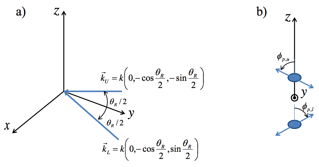
Figure 5 shows a simple sketch of the optical dipole force (ODF) laser beam set-up. As discussed below, the frequency as well as the beam polarizations were chosen to null the AC Stark shift from an individual beam and to produce a state-dependent force that is equal in magnitude but opposite in sign for the and qubit states ( ). This reduced the system sensitivity to laser intensity fluctuations. For example, if , then the interaction induced by the optical dipole force will include terms linear in the ’s. These terms can be canceled with spin-echo techniques, but this requires that laser intensity fluctuations are small. Likewise, by adjusting the laser polarization to null the AC Stark shift from a single beam, we mitigated qubit decoherence due to laser intensity fluctuations. For the benchmarking measurements described here we did not actively stabilize (i.e., noise eat) the laser beam intensity.
The off-resonant laser beam frequency was detuned from the cycling transition by GHz. This gives detunings of GHz and GHz, respectively, from the and transitions (Fig. 4). Laser beam waists were m in the vertical (z-direction) and mm in the horizontal direction. Here we define the waist as the distance from the center of the beam over which the electric field intensity decreases by (i.e. ). With the small incident angle each beam makes with respect to the plane of the crystal, this provided a uniform electric field with intensity variation across ion crystal arrays with .
The ODF laser beams were linearly polarized at nonzero angles with respect to the -axis. Let
| (7) |
denote the electric fields of the upper and lower ODF beams. If is the angle of the laser beam electric-field polarization with respect to vertical polarization , then the AC Stark shift of the qubit states when illuminated by a single beam can be written
| (8) |
where () is the Stark shift of the () state for a -polarized beam ( parallel to the -axis) and () is the Stark shift of the () state for a -polarized beam ( perpendicular to the -axis). (Here we neglect the small polarization () that exists when .) The Stark shift of the qubit transition is
| (9) |
If and have opposite signs, there is an angle which makes . For a laser detuning of GHz, at .
With for each ODF laser beam, we exploit the freedom to choose their polarization in order to obtain a state-dependent force. Specifically, we choose to have a polarization given by and to have a polarization given by . In this case the interference term in the expression for the electric field intensity produces a polarization gradient which results in spatially dependent AC Stark shifts
| (10) |
for the qubit levels. Here is the wave vector difference between the two ODF laser beams, is the ODF beat note, and . The spatially dependent AC Stark shift produces a state-dependent force where
| (11) |
In general We operate at GHz where for we also obtain
For a given , , and we use straightforward atomic physics along with well known values for the energy levels and matrix elements of to calculate as a function of the electric field intensity at the center of the laser beams. For and W/cm2 , N.
Stronger forces can be generated after experimental modification to our apparatus to permit . At this angle larger detunings are required to satisfy Eq. 6 in Methods. With our definition , the interaction strength between two ions and is . Consider for example ions, kHz, powers of mW/beam () and . The spin-motion entanglement constraint is satisfied by a detuning of kHz. In this case we obtain , where is the typical nearest neighbor separation.
III Wavefront alignment
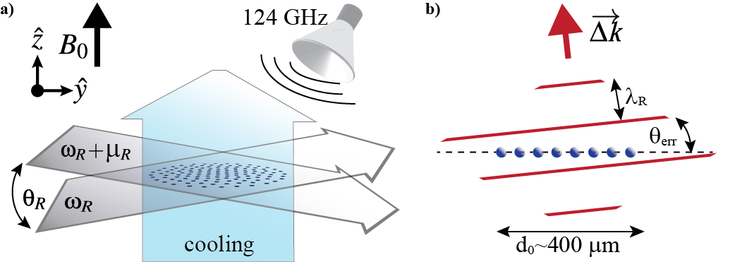
The ODF laser beams produce a one dimensional (1D) optical lattice characterized by the effective wave vector and beat note . In Sec. II we assumed that , or equivalently that the wavefronts of the lattice were aligned perpendicular to the -axis (magnetic field axis). If the wavefronts are not normal to the -axis as sketched in Fig. 6, then the time dependence of the ODF seen by an ion in the rotating frame depends on the position of the ion. This complicates the effective spin-spin interactions generated by the ODF but can be adequately mitigated by careful alignment.
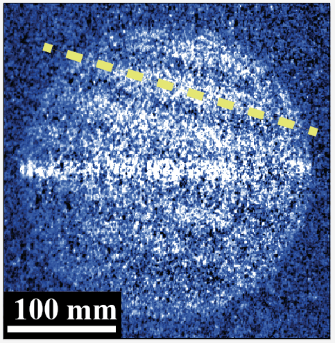
Alignment of the ODF laser beams is obtained by a technique that makes top-view images (images of the ion resonance fluorescence scattered along the magnetic field) from a single plane of ions sensitive to ODF wave front misalignment. For this measurement we set (stationary 1D lattice) and detune the frequency of the ODF laser beams approximately GHz below the Doppler cooling transition. This small detuning generates sufficiently large AC Stark shifts on the cooling transition to measurably change the ion scatter rate from the Doppler cooling laser. With the Doppler cooling laser turned on and the ODF beams turned off, we observe a spatially uniform, time-averaged image of a rotating planar crystal. With the ODF beams on, ions located in regions of high electric field intensity at the anti-nodes of the optical lattice are Stark-shifted out of resonance with the Doppler cooling laser. This is the cause of the dark bands in the top-view image shown in Fig. 7. We adjust the ODF laser beams based on this real-time imaging to optimize their alignment. Improved alignment is indicated by a fringe pattern of longer wavelength. With this technique we have aligned the ODF wave fronts with the planar array to better than .
The image in Fig. 7 is typical of what we obtain with integration duration. This indicates the 1D lattice was stable during the integration period and shows the phase stability of our 1D lattice of better than .
We note that direct fluorescence imaging of the 1D lattice, for example by tuning the ODF laser resonant with the Doppler cooling transition, is not viable. Even at low powers, resonantly scattered photons across the large horizontal waist of the ODF beams apply a large torque, causing the rotation frequency and radius of the array to rapidly change, typically driving the ions into orbits of very large radius.
We have also used phase coherent Doppler velocimetry to improve the ODF wavefront alignment Biercuk et al. (2011). But the top-view imaging technique discussed here and shown in Fig. 7 provides more information on the angle and direction of misalignment, which greatly improves the ODF-crystal alignment process.
IV Modeling mean field spin precession
For any spin , , which implies constant under application of . The Hamiltonian describing the mean field response of spin to the application is obtained by expanding to first order in :
| (12) |
Defining , can be written
| (13) |
The mean field Heisenberg equations of motion for spin is obtained from the commutator of and . However, because and is a constant, it is clear that Eq. 13 describes spin precession about the z-axis at frequency . Our observable is the spin precession (in excess of ordinary Larmor precession) averaged over all the spins .
We use the spin-echo sequence in Fig. 8 to measure a precession proportional to the expectation value of the spin projection along . The spin-echo sequence minimizes contributions to spin precession that are not . Specifically, the spin echo cancels a constant spin precession independent of (e.g., due to slow uncontrolled magnetic field fluctuations), but precession coherently adds in the two arms of the sequence.
The first pulse sets . The interaction is then applied by turning on the ODF laser beams for a period . During this interval is a constant and mean field theory predicts an average spin precession angle of . The -pulse changes and the spin precession angle to . At the end of the second interaction of duration , the total precession angle of the spins is . The final -pulse is about an axis shifted by from the first -pulse. This pulse converts precession out of the initial plane into excursions above or below the equatorial plane of the Bloch sphere, which we measure.
The evolution operator of the measurement sequence is obtained in a straight forward manner from the individual evolution operators from each segment of the sequence,
| (14) |
Here , and . The mean field evolution is given by
| (15) |
where in the first arm of the spin-echo sequence and in the second arm. At the end of the sequence we detect the state probability. Explicit computation gives
| (16) |
V Optical dipole force laser intensity calibration
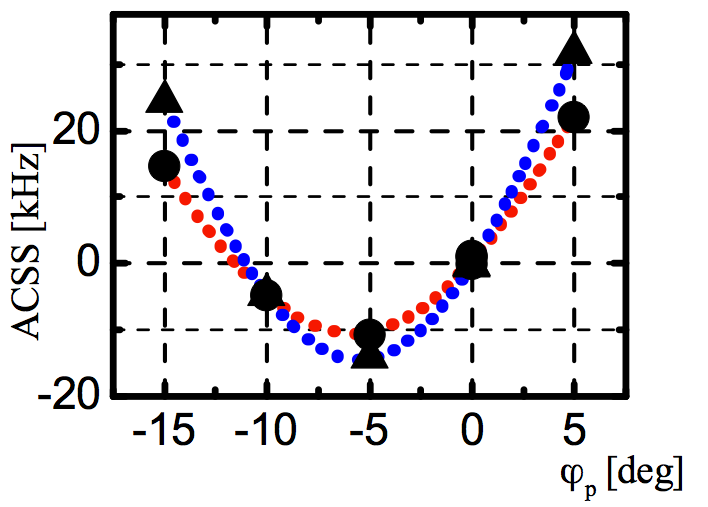
The spin-spin couplings () measured here depend on the square of the ODF electric field intensity . Therefore, careful calibration of the electric field intensity was important in benchmarking the strength of the interactions with mean-field predictions. We separately determined for each beam by measuring the AC Stark shift of the qubit transition as a function of the laser beam polarization angle , as shown in Fig. 9. The qubit transition frequency was measured by fitting for the center frequency of a Rabi-resonance profile. The polarization angle was varied by rotating a /2 plate. The Stark shift measurements were fit to Eq. 9, which provided values for and (Stark shifts for -polarization and -polarization). Values for and were then used with atomic physics calculations to determine , the electric field intensity of the ODF laser beams, with a fractional uncertainty of . Frequent intensity calibration measurements were taken during a benchmarking run. Slow drifts to the laser intensity between calibrations added another uncertainty, which we add in quadrature to the fitted uncertainty.
VI Spontaneous emission
Decoherence due to spontaneous emission has been well studied in this system Uys et al. (2010). The qubit levels are closed under spontaneous light scattering; that is, spontaneous light scattering does not optically pump the ion to a different ground state level outside of the two qubit levels. We measure spin precession to benchmark the Ising interaction couplings. Equivalently we measure the evolution of off-diagonal coherences between the and levels. Spontaneous-emission-induced decay of these coherences is accurately modeled by Eq. (8) of Ref. Uys et al. (2010). We add this time dependence to the unitary evolution discussed in Sec. IV. This results in the expression
| (17) |
where is the probability of detecting a spin in at the end of the spin-echo sequence. The only difference with Eq. 16 is the factor due to the decay of the off-diagonal elements of the density matrix. Here accounts for decoherence due to spontaneous emission. From Uys et al. (2010), has contributions from both Raman scattering and elastic Rayleigh scattering. A straightforward atomic physics calculation relates to the ODF laser beam intensity . In fits of Eq. 17 to the spin-precession measurements, we fix at the value determined by the laser intensity calibrations. For GHz, , and W/cm2, we calculate s-1.
With our present set-up we can achieve for detunings kHz. For these detunings it will be possible to simulate quantum effects beyond mean field theory such as spin squeezing and spin-depolarization due to many-body interactions. For example we calculate that with mW/beam and an ODF beatnote detuning of kHz , kHz and . The potential spin squeezing due to this interaction is dB, limited by spontaneous emission. For many simulations it will be desirable to achieve where is a nearest-neighbor coupling strength. ( for small detunings .) The most straight forward strategy to achieve this condition in our set-up appears to be to increase the angle between the Raman beams. The ratio scales as . Therefore decoherence due to spontaneous emission can be dramatically reduced with an order of magnitude increase in We note that a large increase in will require implementation of a sub-Doppler cooling scheme to remain in the Lamb-Dicke regime (see Sec. VII).
Different ODF laser detunings can likely help reduce the impact of spontaneous emission (with the complication that ), but very large laser detunings obtained by tuning the ODF laser beam frequencies outside the manifold appear unlikely to help. This is because both the interaction strength and spontaneous emission scale as for our qubit, which is not a clock transition. For trapped-ion experiments in low magnetic field, the impact of spontaneous emission is typically minimized by tuning the ODF laser beam frequencies between the and manifolds. Because the 9Be+ -state fine structure ( GHz) is comparable to the Zeeman splittings for our magnetic field ( T), this approach does not significantly help. However, it can help with heavier mass ions (e.g., Mg+). Reference Baltrusch et al. (2011) discusses a number of strategies that can minimize the impact of spontaneous emission when the -state fine structure is large compared to the Zeeman interaction energy.
VII Lamb-Dicke confinement
Throughout this manuscript we implicitly assume that the applied state-dependent force, , is constant across the spatial extent of an ion’s wave function. Specifically, for a planar array located at , we assume the force on any ion is given by
| (18) |
The extent to which this is true is quantified by the parameter
| (19) |
where is the root mean square (rms) axial extent of the wave function of ion and , where m for . We note that is a Lamb-Dicke confinement parameter for a individual ion (ind), not to be confused with the usual Lamb-Dicke parameter that is defined in terms of the ground-state wave function. In the limit that the Coulomb interaction energy between ions is a small perturbation to the axial potential of the trap, we can think of each ion as a single ion confined in the external trap potential, and approximate , where is the mass of an individual ion. Recently we have completed careful axial temperature measurements for single-plane ion crystals Sawyer et al. (2012). We find mK for the axial COM mode and mK for the higher order transverse modes. For kHz and conservatively assuming mK, we calculate , nm, and .
For the benchmarking measurements described here we typically set the rotation frequency of the ion array about kHz below the rotation frequency of the plane transition, determined experimentally from side-view images Mitchell et al. (1998). In this case, the spectrum of the transverse (axial) modes is broad, and we underestimate in the above analysis. An improved estimate of is obtained by summing the contributions from all of the transverse modes
| (20) |
where is the mean thermal occupation of mode . We assume here that every mode is characterized by the same temperature T. For and kHz, the rotation frequency of the plane transition is kHz. For kHz, the spectrum of the axial modes ranges from kHz down to kHz. With Eq. 20 we calculate nm in the center of the array, decreasing to nm at the array edge, corresponding to for near the array center and for near the array boundary.
The wavefront alignment discussed in a previous section can be viewed as achieving a type of Lamb-Dicke confinement. Let denote the angle of misalignment between the planar array and the ODF 1D lattice (Fig. 6). Relative to the ODF lattice wavefronts, the rotation of the array produces a time-dependent shift in the axial position of an ion that can be written as . Here R is the distance of the ion from the center of the array, and is determined by the azimuthal position of the ion in the array. The force on this ion is then
| (21) |
For Eq. 21 to approximate Eq. 18, we desire , where is the array radius. For m (typical for ) and (see Wavefront alignment section), we calculate .
VIII Ion lattice configuration at equilibrium and transverse normal modes
The ion equilibrium positions at zero temperature are calculated by minimizing the Euler-Lagrange action for the Penning trap potentials and the constraint that the ions lie in a plane (at ). The solution is a triangular lattice with a lattice constant that increases as one moves radially outward, that has a smooth unfaceted edge and exhibits a degradation in orientational order near the crystal perimeter. The transverse (along ) phonon modes (, ) are obtained by Taylor expansion of the potential about the ion equilibrium positions . In-plane modes (along ) can also be calculated, by solving a quadratic eigenvalue problem (due to inclusion of the centrifugal and Coriolis forces). The details of the transverse mode calculation is discussed in this section. The problem has also been solved for longitudinal and transverse modes in 1D (e.g., James (1998); Marquet et al. (2003)).
In general, the Lagrangian for a collection of ions with charge and mass in an electromagnetic field is
| (22) |
where is the coordinate of ion . In a Penning trap, the field consists of a uniform magnetic field in the -direction () and a harmonic trapping (anti-trapping) electric potential in the -direction (-direction) with frequency . Lastly, an additional external time-dependent electric quadrupole potential (the “rotating wall”, amplitude at the ions) is applied to control the ion’s rotation frequency in the trap Bollinger et al. (2000). Thus, the scalar potential for ion is
| (25) |
where the ion-ion separation is and . Since is uniform, the vector potential energy is
| (26) |
The position of the ions at equilibrium is calculated as follows. We move to a rotating frame where the ions’ coordinates are stationary by using the coordinate transformation , a counterclockwise rotation. The ions’ equilibrium positions can be found by solving the transformed Euler-Lagrange equations . To seed the numerical solution, we supply an initial guess for the 2D crystal: a regular, triangular lattice. Consistent convergence requires ion numbers corresponding to closed shells (e.g., has six closed shells). We find ion equilibrium positions that deviate from a perfect triangular lattice near the crystal periphery and which have an overall ellipticity due to .
Given , the crystal’s transverse eigenmodes can be calculated by Taylor expansion of the potential about the equilibrium positions . The Lagrangian is
| (27) |
where is the axial displacement of -th ion and is the symmetric stiffness matrix evaluated for the equilibrium configuration as
| (28) |
By minimizing the action with respect to the rotating frame axial coordinates , we obtain equations of motion
| (29) |
Following standard normal mode analysis, the solution is obtained by calculating the eigenmodes of the matrix . The result is eigenvalues (with corresponding frequencies ).
IX Limits to the validity of mean field theory
Here we calculate the domain over which a mean field theory (MF) treatment of is valid. In the special case of uniform Ising coupling (e.g., ), we have
| (30) |
where we have neglected a constant offset and is the -component of the total composite spin of the system. The interaction strength is independent of ion-ion separation and is given by
| (31) |
We start each experiment with spins all prepared in the state. Here we use the composite spin picture where this state is labeled . (Formally labels a state that is an eigenstate of and with eigenvalues and , where is the total system spin.) The first pulse of the spin-precession measurement sequence rotates the composite Bloch vector by an angle . After the rotation by the state can be written as
| (32) |
where the coefficients are significantly non-zero for a small range centered on , where . For a coherent spin state, .
We want to establish that a interaction looks like precession , at least over short durations. A precession by an angle about the -axis is obtained with the operation ,
| (33) |
We measure expectation values of the total system spin . It is sufficient therefore to consider how these expectation values transform under the rotation ,
| (34) |
For simplicity, only matrix elements of the total spin in the -direction are considered. Identical expressions are also obtained for .
| (35) |
The double sum is eliminated by making use of the property that has only non-zero matrix elements between states with . can be defined to be if or . Similarly
| (36) |
This is to be compared with the same matrix element under the interaction,
| (37) |
Equation 37 approximates a rotation about the -axis (that is, approximates Eq. 36) if for all for which is significantly non-zero. This is satisfied for short periods satisfying . For the initial coherent spin state, , which puts a limit
| (38) |
on the period for which the interaction can be approximated as a precession . The precession frequency predicted by the analysis, , is in agreement with the precession frequency predicted by the MF analysis.
Equation 38 provides a limit on the period for which the MF analysis is valid. We confirm this limit through explicit calculation of the spin precession benchmarking sequence for the interaction with , and spins. The exact calculation is possible because the system remains in the symmetric subspace (dimension of Hilbert space is ). Figure 10(a) shows the results of the calculation for five spins. Reasonable agreement between the MF precession formula (Eq. 17 with ) and the exact calculation is obtained for , but not for and , as expected from Eq. 38. Figures 10(b) and 10(c) compare the exact calculation with the MF formula for and spins. Excellent agreement between the MF formula and the exact calculation is obtained for and . Some differences are observed at . These differences decrease as increases.
a)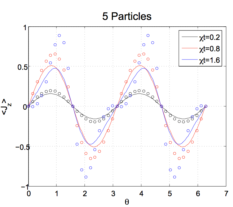
b)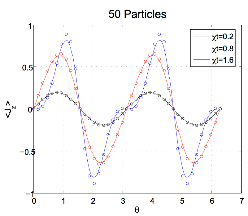
c)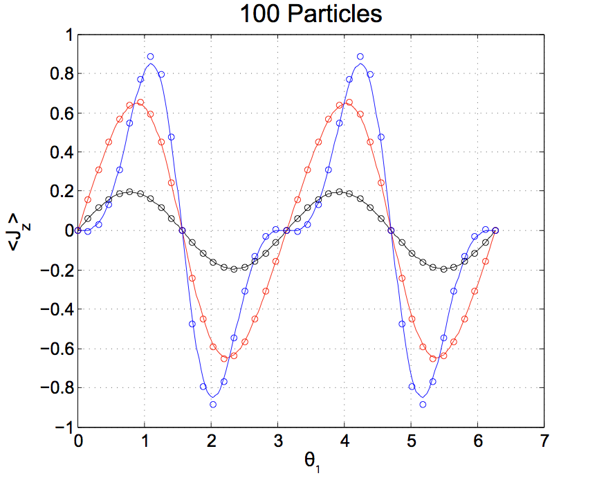
References
- Anderson (1987) P. W. Anderson, Science 235, 1196 (1987).
- Moessner et al. (2000) R. Moessner, S. L. Sondhi, and P. Chandra, Physical Review Letters 84, 4457 (2000).
- Sandvik (2010) A. W. Sandvik, Physical Review Letters 104, 137204 (2010).
- Feynman (1982) R. Feynman, Int. J. Theor. Phys. 21, 467 (1982).
- Buluta and Nori (2009) I. Buluta and F. Nori, Science 326, 108 (2009).
- Trotzky et al. (2008) S. Trotzky, P. Cheinet, S. Fölling, M. Feld, U. Schnorrberger, A. M. Rey, A. Polkovnikov, E. A. Demler, M. D. Lukin, and I. Bloch, Science 319, 295 (2008).
- Lin et al. (2009) Y.-J. Lin, R. L. Compton, K. Jiménez-García, J. V. Porto, and I. B. Spielman, Nature 462, 628 (2009).
- Jo et al. (2009) G.-B. Jo, Y.-R. Lee, J.-H. Choi, C. A. Christensen, T. H. Kim, J. H. Thywissen, D. E. Pritchard, and W. Ketterle, Science 325, 1521 (2009).
- Friedenauer et al. (2008) A. Friedenauer, H. Schmitz, J. T. Glueckert, D. Porras, and T. Schaetz, Nature Physics 4, 757 (2008).
- Kim et al. (2010) K. Kim, M.-S. Chang, S. Korenblit, R. Islam, E. E. Edwards, J. K. Freericks, G.-D. Lin, L.-M. Duan, and C. Monroe, Nature 465, 590 (2010).
- Simon et al. (2011) J. Simon, W. S. Bakr, R. Ma, M. E. Tai, P. M. Preiss, and M. Greiner, Nature 472, 307 (2011).
- Ma et al. (2011) X.-s. Ma, B. Dakic, W. Naylor, A. Zeilinger, and P. Walther, Nature Physics 7, 399 (2011).
- Islam et al. (2011) R. Islam, E. E. Edwards, K. Kim, S. Korenblit, C. Noh, H. Carmichael, G.-D. Lin, L.-M. Duan, C. C. J. Wang, J. K. Freericks, and C. Monroe, Nature communications 2, 377 (2011).
- Lanyon et al. (2011) B. P. Lanyon, C. Hempel, D. Nigg, M. Muller, R. Gerritsma, F. Zahringer, P. Schindler, J. T. Barreiro, M. Rambach, G. Kirchmair, M. Hennrich, P. Zoller, R. Blatt, and C. F. Roos, Science 334, 57 (2011).
- Sachdev (2001) S. Sachdev, Quantum Phase Transitions, Vol. 0 (Cambridge University Press, 2001) p. 353.
- Kohno et al. (2007) M. Kohno, O. a. Starykh, and L. Balents, Nature Physics 3, 790 (2007).
- Varney et al. (2011) C. Varney, K. Sun, V. Galitski, and M. Rigol, Physical Review Letters 107, 077201 (2011).
- Levi (2007) B. G. Levi, Physics Today 60, 16 (2007).
- Helton et al. (2007) J. S. Helton, K. Matan, M. P. Shores, E. a. Nytko, B. M. Bartlett, Y. Yoshida, Y. Takano, A. Suslov, Y. Qiu, J.-H. Chung, D. G. Nocera, and Y. S. Lee, Physical Review Letters 98, 107204 (2007).
- Balents (2010) L. Balents, Nature 464, 199 (2010).
- Mitchell et al. (1998) T. Mitchell, J. J. Bollinger, D. Dubin, X. Huang, W. M. Itano, and R. Baughman, Science (New York, N.Y.) 282, 1290 (1998).
- Lewenstein et al. (2007) M. Lewenstein, A. Sanpera, V. Ahufinger, B. Damski, A. Sen(De), and U. Sen, Advances in Physics 56, 243 (2007).
- Bloch and Zwerger (2008) I. Bloch and W. Zwerger, Reviews of Modern Physics 80, 885 (2008).
- Rosenband et al. (2008) T. Rosenband, D. B. Hume, P. O. Schmidt, C. W. Chou, A. Brusch, L. Lorini, W. H. Oskay, R. E. Drullinger, T. M. Fortier, J. E. Stalnaker, S. a. Diddams, W. C. Swann, N. R. Newbury, W. M. Itano, D. J. Wineland, and J. C. Bergquist, Science (New York, N.Y.) 319, 1808 (2008).
- Schmied et al. (2009) R. Schmied, J. H. Wesenberg, and D. Leibfried, Physical Review Letters 102, 233002 (2009).
- Biercuk et al. (2009a) M. J. Biercuk, H. Uys, A. P. VanDevender, N. Shiga, W. M. Itano, and J. J. Bollinger, Quantum Information and Computation 9, 920 (2009a).
- Leibfried et al. (2003) D. Leibfried, B. DeMarco, V. Meyer, D. Lucas, M. Barrett, J. W. Britton, W. M. Itano, B. M. Jelenkovic, C. Langer, T. Rosenband, and D. J. Wineland, Nature 422, 412 (2003).
- Porras and Cirac (2006) D. Porras and J. Cirac, Physical Review Letters 96, 250501 (2006).
- Kim et al. (2009) K. Kim, M.-S. Chang, R. Islam, S. Korenblit, L.-M. Duan, and C. Monroe, Physical Review Letters 103, 120502 (2009).
- Sawyer et al. (2012) B. C. Sawyer, J. W. Britton, A. C. Keith, C. C. J. Wang, J. K. Freericks, H. Uys, M. J. Biercuk, and J. J. Bollinger, Physical Review Letters (2012), arXiv:arXiv:1201.4415v1 .
- Brewer et al. (1988) L. Brewer, J. Prestage, J. J. Bollinger, W. M. Itano, D. Larson, and D. J. Wineland, Physical Review A 38, 859 (1988).
- Dubin and O Neil (1999) D. H. E. Dubin and T. M. O Neil, Reviews of Modern Physics 71, 87 (1999).
- Porras and Cirac (2004) D. Porras and J. I. Cirac, Physical Review Letters 92, 1 (2004).
- Buluta et al. (2008) I. Buluta, M. Kitaoka, S. Georgescu, and S. Hasegawa, Physical Review A 77, 1 (2008).
- Taylor and Calarco (2008) J. Taylor and T. Calarco, Physical Review A 78 (2008), 10.1103/PhysRevA.78.062331.
- Zou et al. (2010) P. Zou, J. Xu, W. Song, and S.-L. Zhu, Physics Letters A 374, 1425 (2010).
- Baltrusch et al. (2011) J. Baltrusch, A. Negretti, J. Taylor, and T. Calarco, Physical Review A 83, 042319 (2011).
- Biercuk et al. (2009b) M. J. Biercuk, H. Uys, A. P. VanDevender, N. Shiga, W. M. Itano, and J. J. Bollinger, Nature 458, 996 (2009b).
- Biercuk et al. (2009c) M. J. Biercuk, H. Uys, A. P. VanDevender, N. Shiga, W. M. Itano, and J. J. Bollinger, Physical Review A 79, 062324 (2009c).
- Uys et al. (2009) H. Uys, M. J. Biercuk, and J. J. Bollinger, Physical Review Letters 103, 40501 (2009).
- Uys et al. (2010) H. Uys, M. J. Biercuk, A. P. VanDevender, C. Ospelkaus, D. Meiser, R. Ozeri, and J. J. Bollinger, Physical Review Letters 105, 200401 (2010).
- Itano and Wineland (1981) W. M. Itano and D. J. Wineland, Physical Review A 24, 1364 (1981).
- Mitchell et al. (2001) T. B. Mitchell, J. J. Bollinger, W. M. Itano, and D. H. E. Dubin, Physical Review Letters 87, 183001 (2001).
- Itano and Leibfried (1998) W. M. Itano and D. Leibfried, Journal Of Research Of The National Institute Of Standards And Technology 103 (1998).
- Biercuk et al. (2011) M. J. Biercuk, H. Uys, J. W. Britton, A. P. VanDevender, and J. J. Bollinger, Optics Express 19, 10304 (2011).
- James (1998) D. James, Applied Physics B: Lasers and Optics 66, 181 (1998).
- Marquet et al. (2003) C. Marquet, F. Schmidt-Kaler, and D. James, Applied Physics B: Lasers and Optics 76, 199 (2003).
- Bollinger et al. (2000) J. J. Bollinger, T. B. Mitchell, X.-P. Huang, W. M. Itano, J. N. Tan, B. M. Jelenkovic, and D. J. Wineland, Physics of Plasmas 7, 7 (2000).