Non-Paraxial Wave Analysis of 3D Airy Beams
Yan Kaganovsky,∗ and Ehud Heyman
School of Electrical Engineering, Tel Aviv University,
Tel-Aviv 69978, Israel
∗yankagan@gmail.com
Abstract
The 3D Airy beam (AiB) is thoroughly explored from a wave-theory point of view. We utilize the exact spectral integral for the AiB to derive local ray-based solutions that do not suffer from the limitations of the conventional parabolic equation (PE) solution, and are valid far beyond the paraxial zone and for longer ranges. The ray topology near the main lobe of the AiB delineates a hyperbolic umilic diffraction catastrophe, consisting of a cusped double-layered caustic, but this caustic is deformed in the far range where the field loses its beam shape. The field in the vicinity of this caustic is described uniformly by a hyperbolic umilic canonical integral which is structured explicitly on the local geometry of the caustic as obtained from the initial field distribution. In order to accommodate the finite-energy AiB we also modify the canonical integral by adding a complex loss parameter. The canonical integral is calculated using a series expansion and the results are used to identify the validity zone of the conventional PE solution. The analysis is performed within the framework of the non-dispersive AiB where the aperture field is scaled with frequency such that the ray skeleton is frequency-independent. This scaling enables an extension of the theory to the ultra wide band (UWB) regime and ensures that the pulsed field propagates along the curved beam trajectory without dispersion, as will be demonstrated in a subsequent publication.
1 Introduction
Airy beams (AiB) are exact solutions of the time-harmonic parabolic wave equation (PE) in free space, that are generated by an Airy function initial condition in an extended aperture. The AiB’s have attracted a considerable attention mainly because of their intriguing features, the most distinctive one is the propagation along curved trajectories [1, 2, 3, 4]. Other intriguing properties are the weak diffraction [2] and self-healing (i.e., regeneration of the solutions if the beam is partially obstructed) [5]. Many interesting applications that utilize these properties have been suggested, e.g. [6, 7, 8, 9, 10].
In a previous paper [11], we provided a cogent wave-based description to the 2D-AiB’s that clearly explains all these features. Using uniform asymptotic evaluation of Kirchhoff’s radiation integral [12] and uniform geometrical optics (UGO) [13, 14], it has been shown that the AiB is not generated by the main lobe of the Airy function in the aperture, but it is in fact a caustic of rays that emerge sideways from the side lobes of the extended aperture distribution. This implies that the AiB cannot be regarded as a “beam field” in the sense that the evolution of the main lobe along the curved propagation trajectory is not described by a local wave dynamics. It has also been established that ray theory in conjunction with the UGO provides an accurate solution for the AiB, which fully agrees with the conventional PE solution of [1, 2] when the latter is valid. The UGO solution is accurate even at large observation ranges where the PE solution fails due to the curving beam axis. It has been noted that these ray-based tools can be used to construct other curving beam solutions in uniform and non-uniform media by back-projecting the rays from the caustic to the aperture and synthesizing the aperture distribution that focuses onto that caustic [11]. This concept has been applied recently in [15].
Using the ray description of [11] we have also constructed in [16] a class of non-dispersive Airy pulsed beams (AiPB). These solutions are obtained by synthesizing the aperture field distribution such that the ray skeleton is the same for all frequencies. This scaling of the aperture distribution, unlike previous suggestions [17], ensures that all frequency components focus on the same curved caustic, thus giving rise to a pulse that propagates along the curved trajectory with no dispersion. A closed-form time-domain expression for the AiPB has also been derived in [16] using the spectral theory of transients (STT) [18, 19, 20].
The main goal of this paper is to clarify the wave mechanism of the 3D-AiB by deriving uniform ray-based solutions that reveal the local features of the field. Furthermore, these solutions rely on the exact ray and caustic topology of the AiB and therefore do not suffer from the limitations of the conventional PE solution. We note that due to the curving of the beam trajectory, the PE solution is valid only for short propagation distances and in particular it does not predict the termination of the AiB at a certain range, as will be discussed here. In order to meet this goal we first analyze the ray topology of the 3D-AiB (Sec. 3) and then use this analysis to derive uniform solutions that are structured explicitly upon the local geometry of the caustic (Secs. 4-5). As will be explained below, we emphasize here local uniform solutions rather than globally uniform solutions since the former yields explicit solutions that explain all the parameters and features of the field. The analysis is performed within the framework of the 3D non-dispersive AiB, defined in Sec. 2 such that the ray skeleton is frequency-independent. The non-dispersive formulation not only simplifies the ray analysis by making it more transparent, but it also enables the construction of the non-dispersive AiPB as noted above. This subject will be explored in a subsequent publication [21], where the results of the present work will be used to synthesize 3D-AiPB and to derive closed-form time-domain solutions.
In Sec. 3 we study the exact ray and caustic topology of the 3D-AiB, concentrating on the region near the curved beam axis and deferring the discussion on the global caustic topology to Sec. 6. The analytical details are summarized separately in Appendix A. The topology near the beam axis has many intricate features and it is considerably more complicated than the approximate ray topology of the 3D PE solution in [7] or the 2D case in [11]. Specifically, we show that the main lobe of the AiB is described by a cusped double-layered caustic which is of the hyperbolic umbilic type [22, 23, 24, 25, 26] (see Figs. 4–5). We also identify the range where the isolated hyperbolic umbilic caustic that describes the AiB field near its propagation axis, evolves into the more complicated parabolic umbilic caustic considered in Sec. 6, so that the AiB loses its form. It should be noted that these caustic evolutions (unfoldings) are expected from catastrophe theory principles (see e.g., Fig. 4.4 and Fig. 7.3.(3-5) in [24], respectively), yet, in this paper we provide explicit expressions for this overall topology and also use it to construct the field solution, as described below.
The field calculations are considered next in Secs. 4–5. We start from the exact spectral diffraction integral for the AiB, and then discuss its asymptotic evaluation in terms of geometrical optics (GO). The field near the beam axis, where the ray topology is of the hyperbolic umbilic type, is considered separately in Sec. 5 within the framework of diffraction catastrophe theory [27, 28, 24], discussed below.
Catastrophe theory [27, 28, 24] classifies the caustic topologies in stable polynomial forms, referred to as elementary catastrophes. This also provides a systematic framework for calculating the field near caustics with arbitrary topologies. The general methodology is to map the original integral representation of the field, expressed either spatially or spectrally (e.g., Kirchhoff or plane-wave integrals, respectively), onto the diffraction catastrophe integral corresponding to the elementary catastrophe that describes the caustic. This integral, also referred to as canonical integral, constitutes a standard special function [29, Sec. 36.2].
The mapping of the diffraction integral into the canonical catastrophe integral may be applied globally via a systematic method first introduced in [30, Sec. 5]. This method extends to multi-dimensions the method of Chester et al. [12] (see also [31, 32]) for uniform asymptotic evaluation of 1D integrals with several nearby stationary points and singularities [31]. The global mapping approach, while very elegant and systematic, leads to implicit representations where the field is described in a generalized coordinate system that has to be calculated numerically. Alternatively, this mapping may be performed locally around any given point in configurational space, leading to explicit field representations where the generalized coordinates are the local Cartesian coordinates. In this paper we utilize the local mapping approach since our goal is to explore the wave mechanism of the 3D-AiB by deriving explicit field solutions where all the parameters are directly related to the aperture field distribution. We start in Sec. 5.A by mapping the exact AiB spectral integral in the vicinity of the curved beam axis, ending up with a hyperbolic umbilic diffraction integral for the field. Next in Sec. 5.B we extend this integral to the case of finite-energy AiB’s by adding a complex loss parameter into the phase of this integral. In Sec. 5.C we calculate this integral by extending the closed-form series expansion of [29, Sec. 36.8] to finite energy AiB’s. Finally, in Sec. 5.D we use this solution in order to check the validity of the conventional PE solution, and demonstrate that the latter suffers from a translational error due to an error in the beam axis under the PE approximation.
2 Non Dispersive Airy Beams
In a previous paper [11] we have dealt with the ray interpretation to the 2D-AiB and demonstrated that its curved propagation trajectory is a caustic of rays that emerge sideways from an extended aperture. Based on this concept we have extended the 2D-AiB to the ultra wide band (UWB) frequency domain and to the short-pulse time domain, by employing an initial field distribution that gives rise to a frequency-independent ray skeleton, thus ensuring that all frequency components propagate along the same trajectories and focus onto the same caustic [16].
Extending this concept to the 3D case, the non-dispersive AiB field in the half-space is generated by the aperture field distribution in the plane
| (1) |
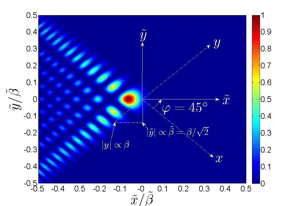
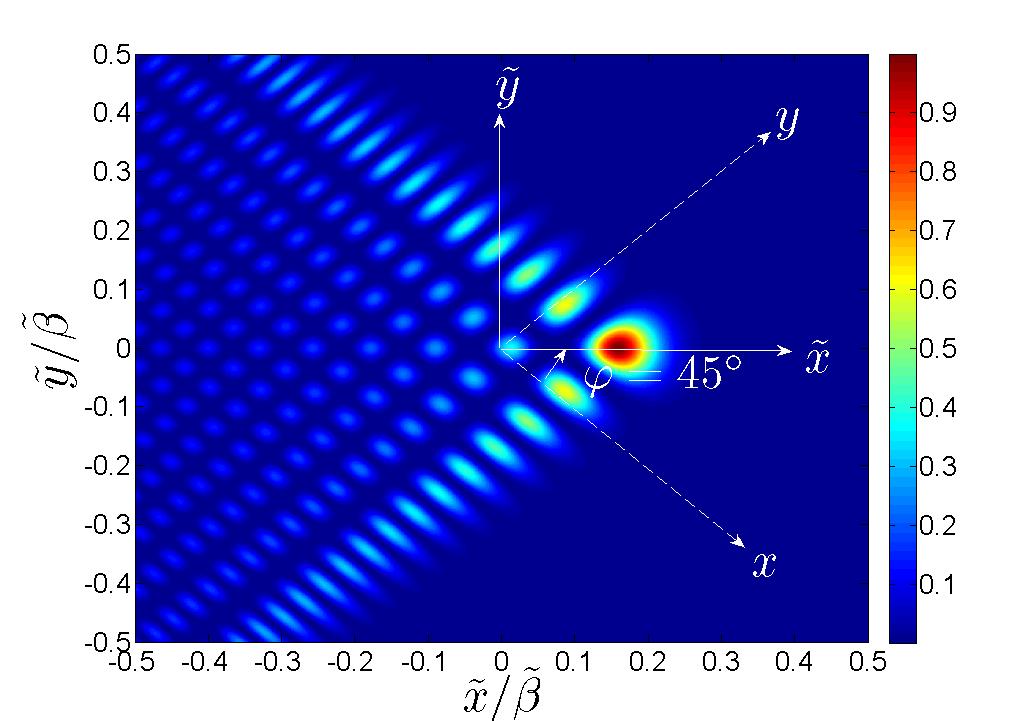
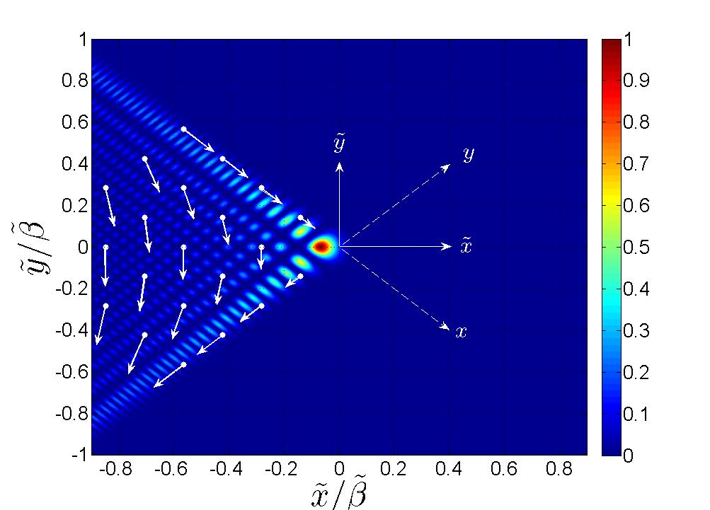
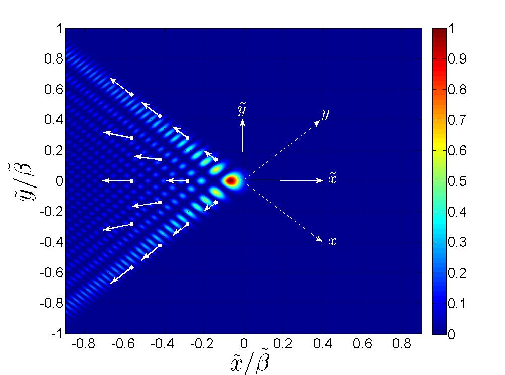
where are the transversal coordinates, Ai is the Airy function, and a harmonic time-dependence is assumed and suppressed throughout. is the wave-number and the wave-speed is assumed uniform. The exponential window in Eq. (1) is added in order to render the energy of this distribution finite. The parameters , are frequency independent scaling factors, with controlling the widths of the field distribution along the and axes, respectively, and controlling the decay rates along these axes (see Fig. 1).
It should be noted that the conventional expression for the AiB initial condition of Eq. (1) is [5, Eq. (2)]. The scaling parameters in this expression are related to those in Eq. (1) via , and . We prefer the frequency independent parameterization since it renders the ray skeleton and the propagation trajectory frequency independent (see Eq. (10) and Sec. 3).
The radiating field at due to the distribution in Eq. (1) has a closed-form solution within the parabolic wave equation (PE) which can be expressed as [5]
| (2) |
where is given by
| (3) |
The beam trajectory is defined by the vanishing of the arguments of the Airy functions in Eqs. (2)–(3), and is given by111 Actually, the peak trajectory is described by replacing the on the right hand side of Eqs. (4)–(5) by the asymptotically small parameter where is the first zero of [29, Table 9.9.1].
| (4) | |||
| (5) |
Note that the parameterization implies that the beam trajectory is frequency independent.
For later use we introduce the coordinate system such that the beam trajectory is contained in the plane (see Fig. 1). This system is obtained by rotating the system at the angle about the -axis, viz
| (6) |
where the superscript defines the transpose of a matrix and is the rotation matrix
| (7) |
For simplicity, but without loss of generality, we shall consider the symmetrical case
| (8) | |||
| (9) |
such that (see Fig. 1). The parameters in the system are defined conveniently as and , and the beam trajectory (the “beam axis”) is given by
| (10) |
The general case can be reduced to the symmetrical case by the scaling , and applying the exponential windows in the new coordinate system.
The solution in Eqs. (2)–(3) is derived within the PE (paraxial) approximation and is therefore inaccurate at large distances where the AiB propagation trajectory curves. The ray solution of Secs. 4–5, on the other hand, remains accurate even at large distances since it is structured upon the ray skeleton of the exact wave equation. The ray solution also provides a clear physical interpretation for the AiB and a tool for constructing other curving beam solutions in uniform and non-uniform media.
3 Ray System and Caustic Topology
3.A Ray System
The properties of the AiB are fully described by the ray system that emerges from the aperture plane. We therefore start with the ray-system topology. Position along a ray can be expressed as
| (11) |
where is the ray initiation point in the plane, is the distance along the ray, and defines the ray direction viz
| (12) |
with being the ray angles with respect to the ,, axes, respectively, and
| (13) |
In order to find for a given initiation point we substitute in Eq. (1) the asymptotic form of the Airy function,
| (14) |
and recast the initial field in the form
| (15) |
where
| (16) | |||
| (17) |
with the signs in Eq. (16) taken as , , , , for , respectively. In Eq. (15), for , for and for . We assumed here that is small so that the decay term is slowly varying on a wavelength scale and can be included in the amplitude rather than in the phase term . This assumption is justified in Sec. 4.B.
One finds that each point in the aperture plane, with , emits four rays, corresponding to in Eq. (15). The ray directions are obtained by local matching to the phase gradient viz
| (18) |
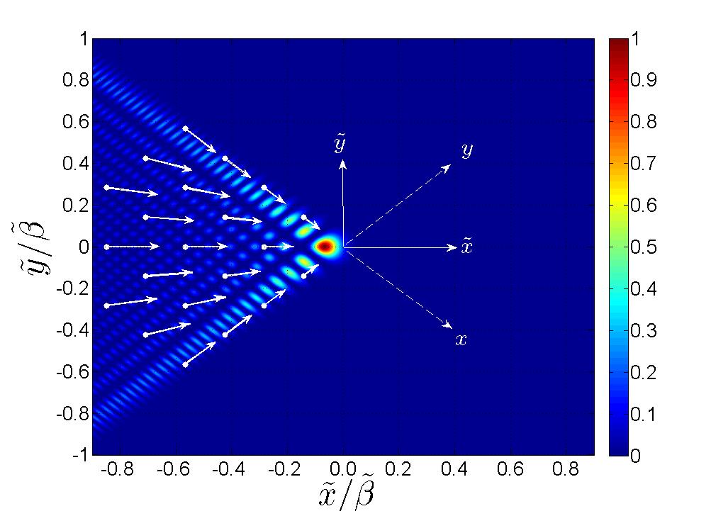
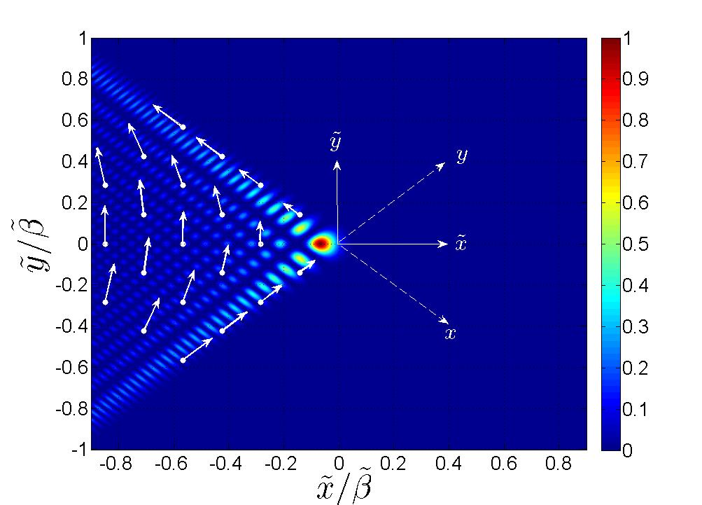
where the “” signs are taken as explained in Eq. (16). Note that the ray directions are frequency independent if is frequency independent. The directions of the four ray species projected onto the plane are depicted in Fig. 2. Finally, we note that the result in Eq. (18) has been derived asymptotically via Eq. (14), but as shown in Appendix A.1, it is also valid exactly.
The ray trajectories in Eq. (11) are parameterized in terms of the ray coordinates where the ray direction tags the initiation point via Eq. (18). The topology of the ray system is described by the Jacobian of the mapping from the coordinates to the ray coordinates , defined by
| (19) |
where and denotes the determinant. An explicit expression for is obtained by noting from Eq. (18) that the exit point coordinates are defined by the ray coordinates via . Substituting in Eq. (11) and calculating the derivatives in Eq. (19) we obtain
| (20) |
The mapping is singular when . This condition defines the envelope of the ray system, also termed caustic surface or catastrophe [24, 28]. The structure of the caustic near the beam axis is discussed next in Sec. 3.B, with further details in Appendix A. The complete caustic topology including also regions away from the beam axis is presented in Sec. 6.
3.B Caustic Topology in the Vicinity of the Beam Axis
3.B.1 Caustic topology within the PE model
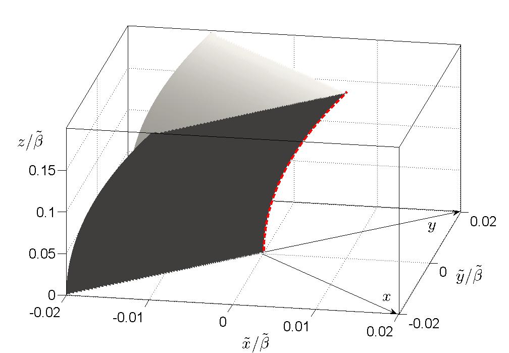
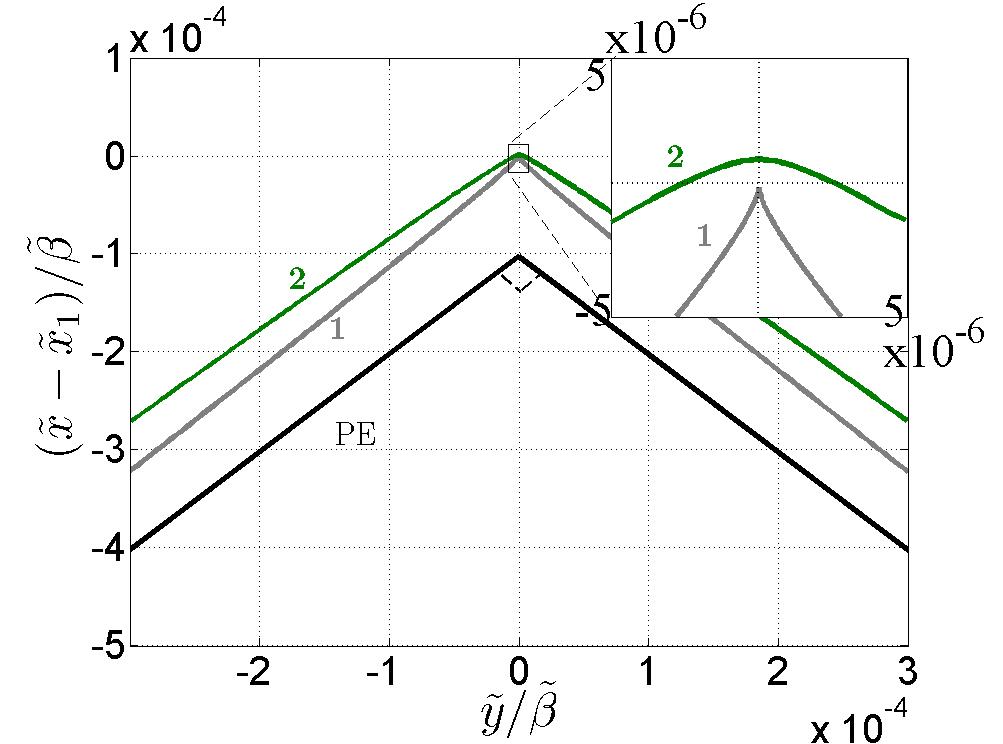
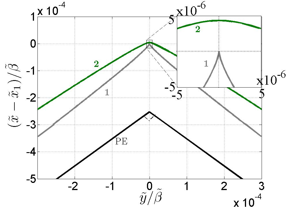
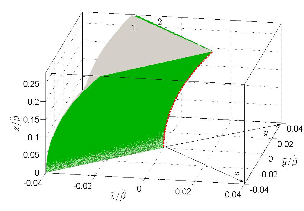
The PE approximation for the beam axis in Eq. (10) is valid only for moderate ranges before the axis curves too much. In this range one may approximate in Eq. (13) . Substituting into Eq. (20) one obtains a closed form solution for the caustic equation (see Appendix A.3). Figure 3 depicts the caustic structure within this approximation. It consists of two curved sheets joined at an edge that delineates the beam axis of Eq. (10). Fig. 4 shows a cross sectional cut of the caustic in two constant- planes, where it is seen to form a right-angled corner. Figure 4 also depicts the exact caustics to be discussed next.
3.B.2 Exact caustic topology along the beam axis
Employing exact ray theory (see Appendix A.2) reveals further details of the caustic, which are also evident from the canonical catastrophe integral to be discussed in Sec. 5. Here we discuss the structure of the caustic near the beam axis; the complete global structure beyond this zone will be discussed separately in Sec. 6.
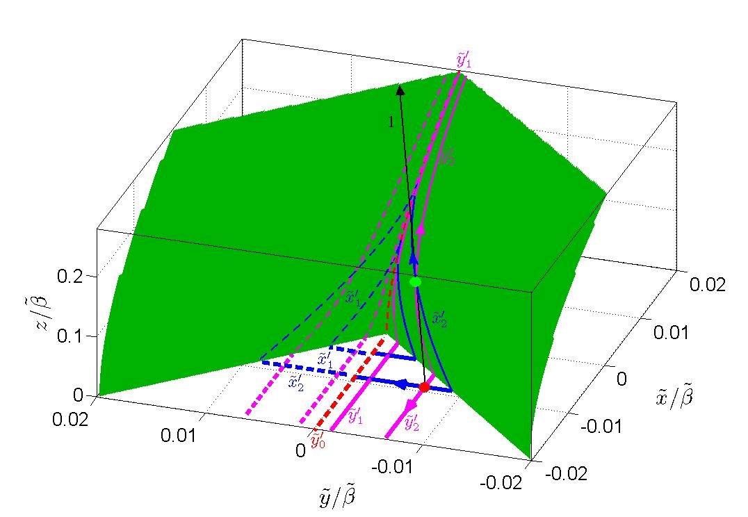
The exact caustic is shown in Fig. 5. It consists of two surfaces, referred to as “caustic 1” and “caustic 2,” each consisting of two sheets joined at an edge. Caustics 1 and 2 are very close and hardly distinguishable on the figure scale. The caustic within the PE approximation is a degenerate case in which caustics 1 and 2 coalesce. Figure 4 zooms on cross-sectional cuts of the caustics at two constant- planes, showing that caustic 1 is a cuspoid, whereas caustic 2 is smooth, and that the distance between these caustics increases with . This topology is identified as a hyperbolic umbilic diffraction catastrophe (see e.g., Fig. 4.4 in [24]) whose focal plane is located at the plane where the two surfaces coalesce along the semi-infinite lines and and form a right-angled corner at the origin.
The explosion of the PE caustic into a hyperbolic umbilic caustic at can also be expected from catastrophe stability theorems [27, 28] as follows from the fact that the right-angled corner at the cross-section of the PE caustic is not a stable form (the only stable forms in 2D are the fold and the cusp; see e.g., Table 3.1 in [24]). Therefore, the corner will not survive the perturbation due to exact propagation222 The PE model is a special case where the effect of the propagation is only a translation (see Eqs. (A.23)-(A.24)) and therefore the caustic retains its unstable shape.. Furthermore, the simplest stable singularity in 3D which contains a corner at a particular cross-section (termed focal plane) is the hyperbolic umbilic catastrophe (see also [33] where a similar argument has been used).
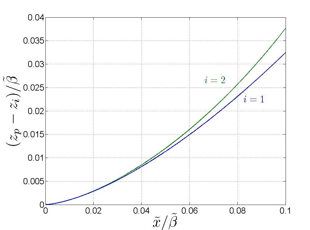
Figure 4 also shows that the deviation of the PE caustic from the exact one increases with , thus limiting the range of validity for the PE solution in Eqs. (2)–(3). In Fig. 6 we concentrate on the difference between the edges of the exact caustics 1 and 2 (Eqs. (A.16)–(A.19)) and of the PE caustic (Eq. (10)) since this edge delineates the propagation trajectory of the AiB.
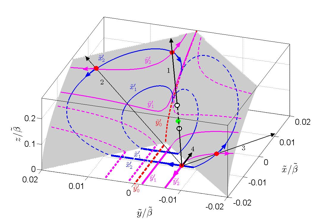
Figures 7 and 8 describe the ray formation of caustics 1 and 2, respectively, by depicting the rays emitted from points in the aperture plane and their point of tangency at the caustics. Actually, the figures show traces of the exit points in the aperture (thick lines), and the traces on the caustics of the corresponding points of tangency (thin lines with the arrows indicating the direction of the traces). To emphasize the symmetry, traces with appear as full or dashed lines, respectively. Lines of constant and of constant are plotted in magenta and blue, respectively.
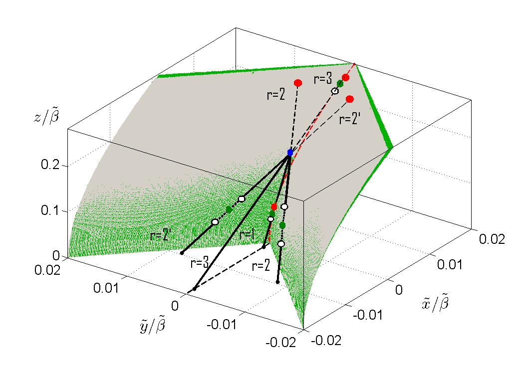
As discussed in Eq. (18) and Fig. 2, each point in the aperture emits four rays, belonging to species . As seen in these figures, caustic 1 is formed by ray species 1,2,3, whereas caustic 2 is formed by species 1 only. Specifically, referring to Fig. 7, the rays of species 2 and 3 touch only caustic 1 (red points), whereas the rays of species 1 penetrate through caustic 1 (through the white circle), then touch caustic 2 (green point; see also Fig. 8), penetrate again through caustic 1 (white circle) and finally touch caustic 1 (red point). In the limit , the rays of species 1 tend to the symmetry plane thus giving rise to the somewhat counterintuitive situation in Fig. 10 where the ray in the symmetry plane penetrates through the edge of caustic 1 and touches caustic 2, but then as it penetrates back through the cusped-edge of caustic 1 it is also tangent to the sheets that generate the cusp (see the blue solid-line trajectory in Fig. 7). This situation will be discussed again in connection with Figs. 9 and 10.
4 Exact Spectral Representation of the Field and Geometrical Optics
4.A Spectral Representation
Using the spectral representation of the Airy function [29, Eq. (9.5.1)], the initial field in Eq. (1) can be expressed as
| (21) |
where is the Fourier kernel, are the spectral variables associated with and
| (22) | |||
| (23) |
The spectral integral in Eq. (21) has been expressed in a normalized non-dispersive form [18] where appears as a linear parameter in the phase and is frequency independent. As a result have a pure frequency-independent geometrical interpretation in terms of the plane wave angle (see discussion below), and is the departure time of the plane wave from the plane. We use this normalization not only because its physical transparency but also since it may be extended to the time-domain [21].
The radiated field, obtained by adding the spectral propagator, is
| (24) | |||
| (25) |
where is the spectral wave-number in the -direction, chosen with for . Consequently the integration extends along the real axes from to such that the contour passes above and below the branch points corresponding to .
Equation (24) expresses the field as a spectrum of plane-waves propagating in the direction defined in terms of via Eq. (12). Note that in Sec. 3, were parameters that define the ray in Eqs. (11)–(12), whereas in this section, they are spectral variables that define the spectral-plane-wave direction. For simplicity we use the same notations and distinguish between them from their context. Actually, the two are related since the ray coordinates of Sec. 3 are stationary points in the spectral domain, as explained after Eq. (26) and also in Appendix A.1.
As noted after Eq. (21), the spectral integral Eq. (24) has a non-dispersive form where appears as a linear parameter in the phase and is frequency independent, describing the arrival time of the plane wave that passes through . This special form will be used in [21] to evaluate the field of the Airy pulsed beam (AiPB).
The direct numerical evaluation of the spectral integral in Eq. (24) is difficult since the integrand is very oscillatory at high frequencies. It may be evaluated asymptotically using the steepest descent method [34] which yields the geometrical optic (GO). Equation (24) will be also used in Sec. 5 in order to calculate the AiB within the framework of Catastrophe theory.
4.B Geometrical Optics
The main contributions in the integral of Eq. (24) come from the vicinity of the saddle points, defined by
| (26) |
with given in Eq. (25). We denote the solutions of Eq. (26) as where is the ray-index. For observation points far away from the caustic, the saddle points are distinct and the field can be expressed in terms of the isolated saddle point contributions [34]
| (27) |
with at . is the determinant of the Hessian matrix
| (28) |
evaluated at , and is determined by the eigenvalues and of , evaluated at , via
| (29) |
Expressions for and are given Eqs. (A.1)–(A.4) and (A.7)–(A.9), respectively. Expressions for , and are given in Eqs. (A.25)–(A.27).
As discussed in Eq. (15), is relatively small and hence we consider first the case . In this case, the saddle points corresponding to an observation points on the lit side of the caustic are real and equal to the ray parameters in Eq. (12) of the rays reaching (see proof in Appendix A.1). The ray-index should not be confused with the species-index introduced in Eq. (15): depending on , the rays described by the th saddle points can be of any species.
The result in Eqs. (27)–(29) can therefore be expressed in the GO form (see details in Appendix A.4)
| (30) | |||
| (31) |
where is the ray length in Eq. (11) and is the Jacobian in Eq. (19), both evaluated at . All squared roots are taken as positive. is the Maslov index that counts the number of times ray has touched the caustic. and in Eqs. (30)–(31) are, respectively, the initial delay and amplitude of the th ray, given by Eq. (16)–(17), with , both are taken at , the initiation point of the th ray. Note that the GO amplitude in Eq. (31) is invalid at the caustics where .
Fig. 9 depicts an illustrative example of the rays reaching a given observation point . For simplicity we consider a point in the vicinity of the beam trajectory where all rays are of species 1 (see Fig. 2(a)). A point on the lit side of the caustic is reached by four rays, tagged by the index . The Maslov index of Eq. (31) in this example is as follows: Ray has not touched the caustic hence ; Rays have penetrated through “caustic 1,” then touched “caustic 2”, and then penetrated again through “caustic 1” (see also ray 1 in Fig. 7), hence ; Ray is has penetrated through “caustic 1”, touched “caustic 2” and then touched the cusp at the edge of “caustic 1” while penetrating it (cf. Fig. 10), so . In addition to the four rays described above, the equation for the rays has three more solutions representing rays that emanate from the aperture at distant points where the field is very weak and the ray angles are very shallow with respect to the plane. These rays will not be considered therefore in the analysis.
Finally, we note that the GO field in Eq. (27) has been derived via an asymptotic analysis of the exact spectral representation, but for it reduces exactly to the asymptotic initial conditions in Eq. (15) that were derived from the asymptotic approximation of the Ai function in Eq. (14).
If then the saddle points become complex. The saddle point analysis above still applies, but the physical interpretation is less transparent. However, since typically is very small, one may expend and of Eq. (27) into Taylor series about the real saddle points for . Keeping terms to leading order in one obtains the result in Eq. (27) with Eqs. (30)–(31) except that here (cf. Eq. (17); see details in Appendix A.4).
4.C The field Near the Caustic
Near the caustic, the ray-system Jacobian vanishes and the GO amplitude in Eq. (31) explodes. From a spectral perspective, the relevant saddle points come close together and the second order asymptotic analysis in Eqs. (27)–(29) is no longer valid. One should resort, instead, to higher order asymptotics that may accommodate two or more nearby saddle points. The simplest situation occurs near the smooth parts of the caustics which are fold catastrophe where two saddle points coalesce. In these regions, the field may be described uniformly via the uniform geometrical optics (UGO) [13, 14] where the field is expressed explicitly in terms of the ray-parameters (i.e., the phase and the Jacobian), but these parameters are combined together so that the solution remains regular near and on the caustic while reducing to the conventional GO expressions further away from it. The simple UGO is not valid near the beam trajectory where the caustic topology is a hyperbolic umbilic as discussed in Sec. 3.B.2 and Figs. 4–8. The field in that region is considered next in Sec. 5.
5 The Field Near the Propagation Trajectory
Near the beam trajectory, the caustic topology is that of a hyperbolic umbilic, hence, as explained in the introduction, we refer to the general framework of catastrophe theory in order to calculate the field. In this approach, the field is represented by the canonical catastrophe integral that can be written as
| (32) |
where are generalized coordinates in the vicinity of the caustic such that is a coordinate along the caustic and are transversal coordinates, and are the spectral variables associated with . has a canonical polynomial form for each elementary catastrophe (see e.g., Eq. (42) for the hyperbolic umbilic). Near the caustic, the integral in Eq. (32) can be evaluated by standard numerical techniques such as series expansion [29, Sec. 36.8] (see also discussion in Sec. 5.C), whereas further away from the caustic, it reduces asymptotically via saddle point analysis to the GO field. The spatial and spectral coordinates in Eq. (32) are typically normalized to be dimensionless and is a normalization constant such that at .
In the theory of diffraction catastrophes [23, 30], the exact integral representation of the field, expressed either spatially (i.e., via a Kirchhoff-type integral) or spectrally, is mapped asymptotically via a method outlined in [30, Sec. 5] into the canonical integral in Eq. (32), thus leading to a globally uniform solution of the field.333Specifically, in the present case, one applies a change of variables such that the stationary points of the phase function in the exact spectral integral in Eq. (24) are mapped to those of the phase in Eq. (32), while satisfying the constraint that the phases at the respective points are equal, i.e., .
As discussed in the introduction, in the globally uniform approach, the generalized coordinates in are related implicitly to the geometrical coordinates near the caustic. Our goal, however, is to obtain an explicit mapping such that these generalized coordinates are directly related to the local Cartesian coordinates along the beam trajectory as shown in Fig. 10, and also to the parameters of the aperture field distribution. Such explicit expressions are obtained by the locally uniform approach of Sec. 5.A where we concentrate on the region near the caustic. In this approach, we transform the exact spectral integral of Eq. (24) to the local Cartesian coordinate system in Fig. 10, and then approximate the spectrum paraxially around the caustic direction. This leads directly to the spectral integral in Eq. (32) where the phase is recognized as hyperbolic umbilic. This integral describes the field in the transition layer around the caustic, but its validity range is much larger and in particular it reduces to the GO field away from the caustic. As discussed in the introduction, this direct approach also provides a convenient tool for the synthesis of other types of beams.
As was done in Sec. 3, we consider first in Sec. 5.A the case where where the rays are real. The modifications for the finite energy AiB where are done in Sec. 5.B. In Secs. 5.C–5.D we discuss the numerical evaluation of the integral.
5.A Mapping the Exact Spectral Integral to the Canonical Form
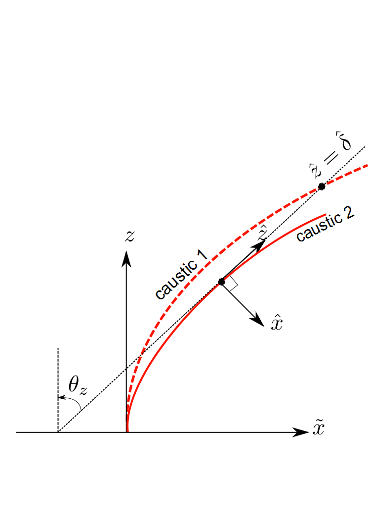
The canonical integral is constructed about a a typical reference point along the beam trajectory, which is taken to be on the edge of caustic 2 (see Fig. 10; recall from the discussion in Sec. 3 that the caustic topology near the beam axis is hyperbolic umbilic, consisting of two sheets denoted as caustic 1 and 2, each has an edge in the symmetry plane , see also Figs. 4–5). This reference point is parameterized, conveniently, by , the angle of the tangent to the edge at this point with respect to the -axis. The coordinates at this point are given by of Eq. (A.15) (see also Eqs. (A.17) and (A.19)). The Cartesian coordinates around this point, denoted as , are chosen such that is the tangent to the edge and are the normal and the bi-normal, respectively (see Fig. 10), and are given, therefore, by
| (33) |
where is the rotation matrix in Eq. (7) with .
The spectral integral in the system is obtained from the one in Eq. (24). We start by expressing the latter in the system of Eq. (6) by rotating the spectral variables such that with given in Eq. (7). Substituting into Eqs. (24)–(25) we obtain
| (34) |
where
| (35) | |||
| (36) |
with . Recall that here we assume .
The spectral variables corresponding to are related to via
| (37) |
with . Substituting Eqs. (33) and (37) into (35), expanding to a Taylor series about , and keeping terms up to third order, we obtain the following expression for
| (38) |
where
| (39) | ||||
| (40) |
in Eq. (39) is the spectral delay at for . Referring to Fig. 10, is identified as the distance along the tangent from the reference point to the cusped edge of caustic 1. From Eq. (37) in Eq. (34) is expressed as where the last term is the approximation for . For one may use and .
Concentrating only on the plane perpendicular to the edge, and normalizing the coordinates, the integral in Eq. (34) with the phase of Eq. (38) can be written in the form
| (41) |
where is given in Eq. (39) and is the canonical integral in Eq. (32) with
| (42) | |||
| (43) |
The normalized spatial and spectral coordinates in Eq. (42) are
| (44) | ||||
| (45) |
and the normalized parameters are
| (46) | |||
| (47) |
where in the second equality in we substituted from Eq. (39), while the last term applies for .
The spectral phase in Eq. (42), which is the simplest polynomial that describes the AiB in the vicinity of the caustic, is of the hyperbolic umbilic type [24, pp. 66],[28, pp. 41]. It follows that the field-scale near the caustic is governed by the factor that scales the local coordinates in Eq. (44). Note that the scaling is expected in view of the general theory of diffraction catastrophes [29, Sec. 36.6].
The caustic topology is controlled by the parameter of Eq. (46) which represents the normalized distance between caustics 1 and 2 such that it scales with frequency like and also grows with the observation range . For , caustics 1 and 2 are far apart and may be described by separated cusp and fold catastrophes, respectively. In this case, the hyperbolic umbilic integral may be reduced to the Pearcey and Airy integrals [29, Sec. 36.2(ii)] that represent, respectively, the field near these catastrophes.
Equation (41) describes the AiB field in a plane normal to the beam axis. The solution in the entire domain along the axis is obtained by tracking the local coordinate system of Eq. (33) along the beam axis. The parameters in Eqs. (39)–(40) are therefore expressed in terms of which describes points on the beam trajectory (see Eq. (A.15)). Since this local spectrum representation is constructed entirely using the ray system topology near the caustic, it follows that the ray approach can be used to construct AiB-type solutions that follow any prescribed convex trajectory by back-projecting the rays to construct the relevant aperture distribution (e.g., the 2D example in [15]).
There are several alternative forms for the hyperbolic umbilic spectral phase , all sharing the “germ”, i.e., the highest order terms of which depend only on and define the catastrophe. The phase in Eq. (42) contains the germ , but there is another form used in [29, Sec. 36.3] which is discussed in Appendix B. The rest of the phase terms, called perturbation terms (or unfolding terms), can have different forms [35, chap. 4] without changing the catastrophe type, as long as they are small. For example, the phase used in [28, pp. 41] is the same as in Eq. (42) with replaced by , but since these are perturbation terms, the two forms are equivalent. In fact, the latter can be obtained by setting the reference point of the local coordinates on the edge of caustic 1 and taking the axis along the direction of the ray that touches the cusped edge there (see point in Fig. 10). We prefer the form in Eq. (42) since in the alternative one, is not tangent to the edge of caustic 1 (see dashed line in Fig. 10) and the tracking along this edge becomes more complicated. Finally, in Sec. 5.B below we extend to the finite energy AiB case.
5.B Finite Energy AiB
Referring to Eq. (35), we now consider the case where . Repeating the procedure thereafter we obtain a polynomial approximation for which is similar to Eq. (38)
| (48) |
except that the coordinate of Eq. (33) and the coefficients , and of Eqs. (39)–(40) are now replaced by
| (49) | |||
| (50) | |||
| (51) | |||
| (52) |
and the term in Eq. (38) now becomes with
| (53) |
For , of Eq. (42) becomes
| (54) |
where
| (55) |
and the other normalized variables are given by Eqs. (45)–(46) with , , , replaced by the corresponding parameters , , , of Eqs. (49)–(52). Note that Eq. (54) reduces back to Eq. (42) for .
Expression (41) for the field becomes
| (56) |
where is the canonical integral in Eq. (32) with given in Eq. (54).
The expression in Eq. (54) has an additional perturbation term (assuming is small ), but as noted at the end of Sec. 5.A, the diffraction pattern of the field will remain hyperbolic umbilic, as can be verified both theoretically and experimentally [1, 5]. The main effect of is an overall amplitude decay which is mainly due to the term in Eq. (56).
5.C Numerical Evaluation of the Canonical Integral
The canonical integral in Eq. (32) with in Eq. (42) or (54) can be evaluated by a straightforward numerical integration. To accelerate the convergence, the integration contours for can be deformed into the complex plane so as to reach infinity along the asymptotic valleys of . Fastest convergence is obtained if the -integration starts asymptotically along the line and ends along the line . Likewise, the integration may start asymptotically along the line and ends along the line . Another approach is to use the 1D integral representation for the hyperbolic umbilic as explained in [29, Sec. 36.15(iii)].
Here we shall use the standard series expansion for the canonical double integral in [29, Eq. 36.8.3] and extend it to the case of finite energy AiB. The small parameters in the series expansion are and . For typical values of such that we may expand into a Taylor series the term appearing in the expression for in Eq. (32) with given in Eq. (54). We obtain
| (57) |
where
| (58) |
Using , in Eq. (57) and taking the derivatives outside of the integral, we rewrite Eq. (57) as
| (59) | |||
| (60) |
with given by
| (61) |
where is given in Eq. (7). Equations (59)–(61) can readily be calculated using standard numerical routines. Note that in the limit , the series representation in Eq. (59) reduces to the standard series expansion in [29, Eq. 36.8.3].
5.D Numerical Example
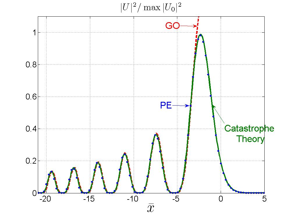
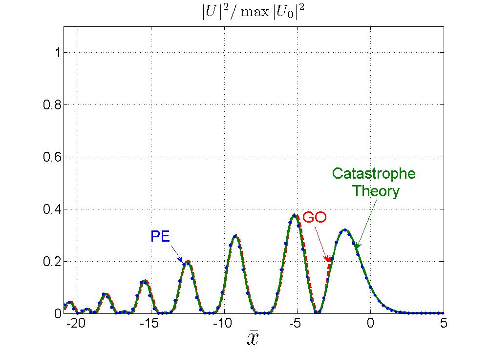
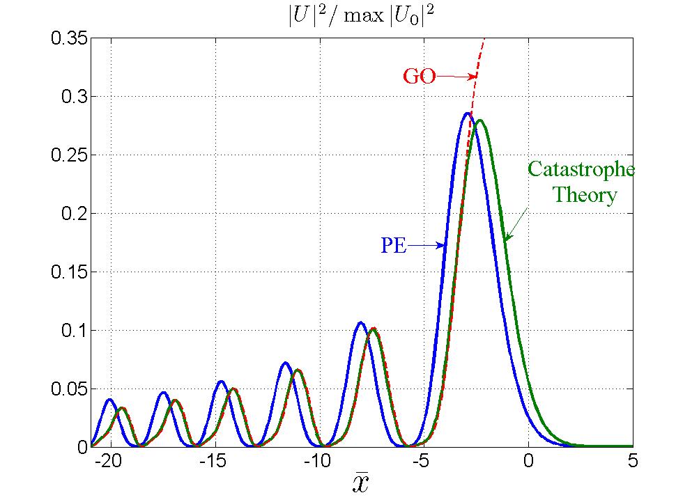
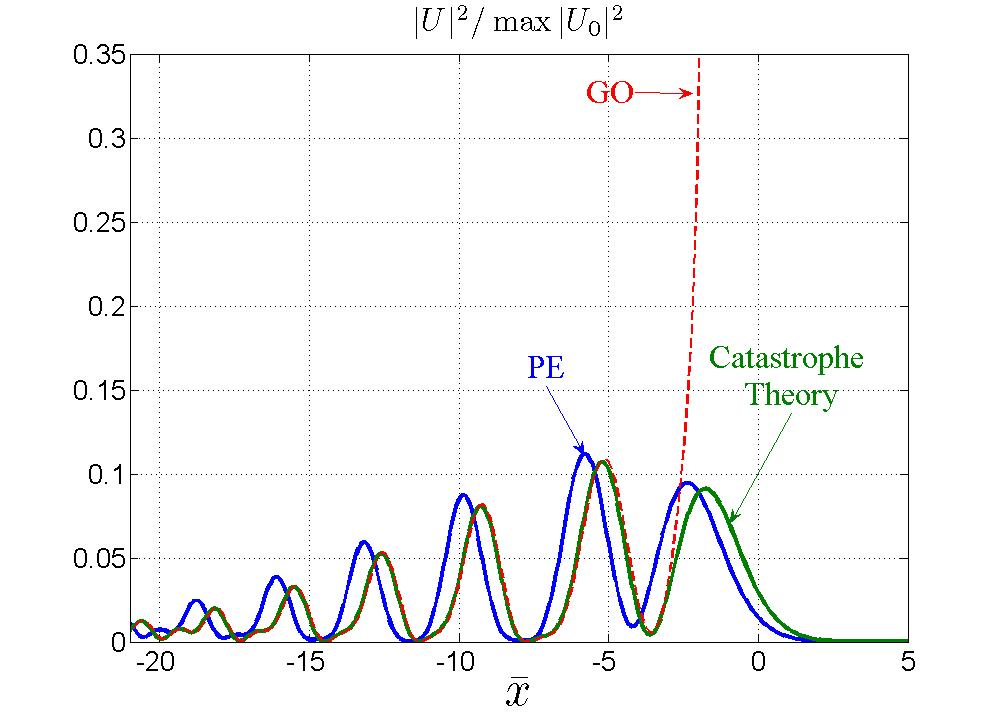
Figures 11 and 12 depict the field intensity at two different frequencies such that and , respectively. The results are shown along the normalized -axis in the and planes. The observation domain is centered at the point on the edge of caustic 2. The figures compare the field calculated via the canonical integral in Eq. (41) (green line), with the PE solution of Eqs. (2)–(3) (blue points), and the GO field of Eq. (27) (red dashed line). The canonical integral has been calculated via the series expansion in Eqs. (59)–(60), keeping only the terms and . A decay parameter has been used.
In Fig. 11 the canonical integral solution and the PE solution are in an excellent agreement on both the lit and the shadow sides of the caustic. As expected, the GO solution breaks on the caustic, but otherwise it agrees well with the other solutions. Further away on the lit side of the caustic, the GO solution starts to deviate, but in this region it is, in fact, more accurate than the other solutions since it does not rely on the local spectrum approximation or on the PE approximation.
In Fig. 12, on the other hand, on observes a significant translational error of the PE solution (notice, on the other hand, the perfect agreement between the canonical integral and the GO solutions, except on the caustic). The error of the PE solution is due to the deviation of the PE-based beam trajectory in Eq. (10) from the true ray-based trajectory, and can be parameterized by which is the normalized location of the PE caustic in the -system (recall from Fig. 10 that the -system is centered on the edge of caustic 2, see also Fig. 4). can be found using Eq. (10) in conjunction with Eqs. (33), (A.14)–(A.15) and (44). Here we consider only the small approximations of , obtaining
| (62) |
In Fig. 11 the frequency is relatively low such that (i.e., ), hence the error of the PE solution is hardly noticeable on the figure scale. In Fig. 12, on the other hand, the frequency is higher giving (i.e., ). Since is , the translational error of the PE solution is readily discerned in the figure.
In addition to the translational error of the PE solution, the exact canonical integral has some intricate features which are readily discerned in the main-lobe of Fig. 12 (notice the peak error of the PE-solution there). Recalling the discussion after Eq. (46), the field structure of the canonical integral is parameterized by which is the normalized distance between caustics 1 and 2. As noted there, this parameter grows with both frequency and observation range. For (near the aperture or small ), the distance between these caustics is small and the canonical integral reduced to the Ai function field structure in Eqs. (2)–(3), but for larger , the field structure of the canonical integral describes the separation between the two caustics and is more complicated than the PE solution. This is seen in Figs. 11 and 12 where and , respectively. In these figures, the cusped edge of caustic 1 is located at and , respectively (i.e., and ).
Finally, to help the reader we map the parameters used in these numerical examples to the conventional ones used for example in [5, 2] (see also discussion after Eq. (1)). Noting that the “Fresnel distance” used there is related to our parameter via , it follows that the range at the caustics in Figs. 11 and 12 is and , respectively.
6 Discussion on the Complete Caustic Topology
We consider the global caustic topology which includes far away parts of the caustic which were not included in the analysis of Sec. 3.B. The field in these regions is formed by contributions of rays that emanate sideways from far away points in the aperture. This global picture is presented here in connection with the discussion in Sec. 6.C regarding the limitations of the AiB. Since the caustic structure is rather complex, we discuss separately the topologies of caustic 2 and 1 in Secs. 6.A and 6.B, respectively.
6.A Global Structure of Caustic 2
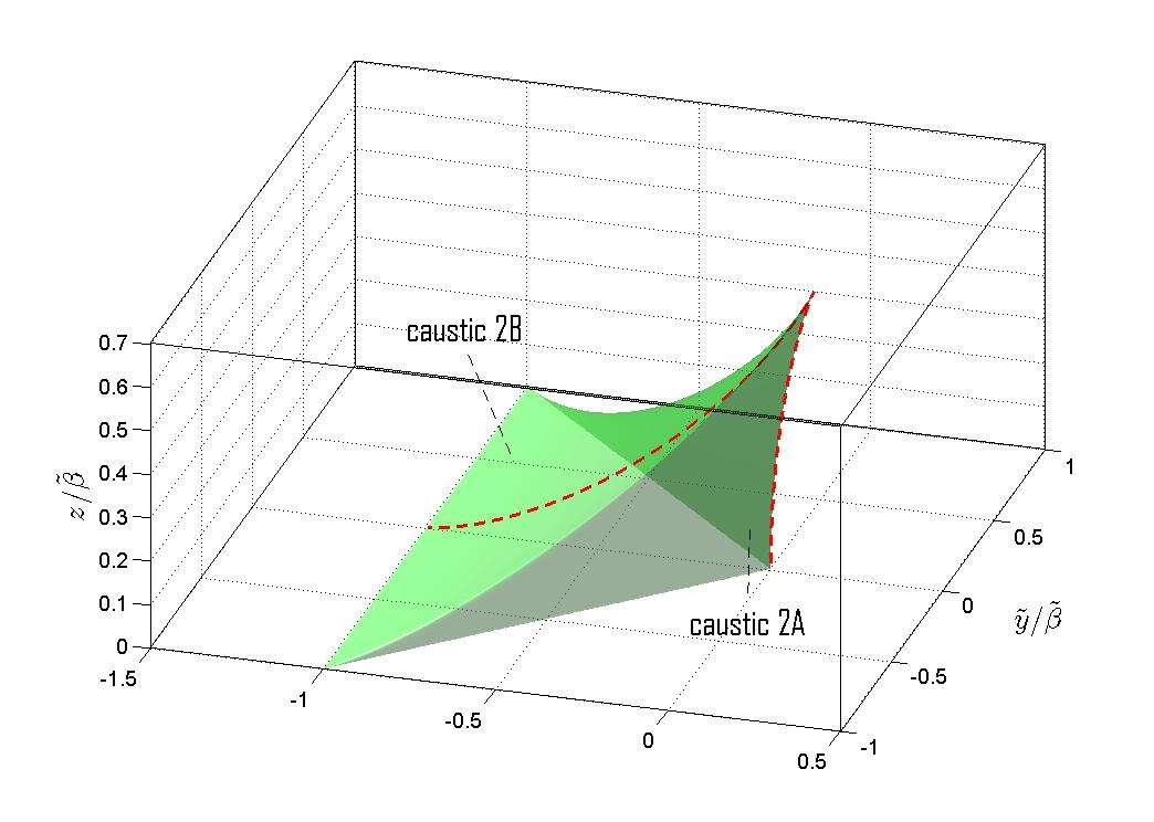
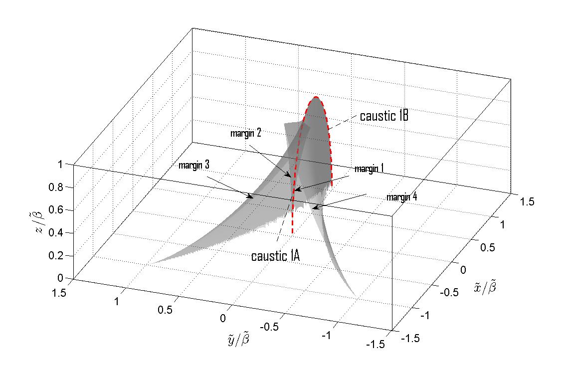
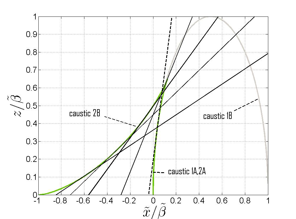
The global structure of caustic 2 is depicted in Fig. 13, as a zoom-out view of Fig. 5. In addition to the sheet shown in Fig. 5, tagged here “caustics 2A”, there is another caustic surface which is tagged “caustic 2B.” These two surfaces are connected and form a pyramid-like structure which terminates at a sharp edge at the top. Caustic 2B is formed by rays exiting the aperture at far away regions, as illustrated in Fig. 16 which shows a cross section of the caustic surface in the (the cross sectional line is also depicted in Fig. 13 by a red dashed-line).
6.B Global Structure of Caustic 1
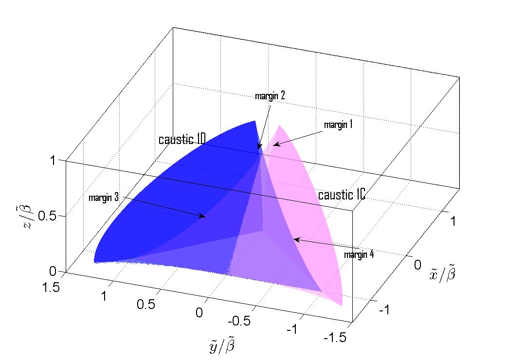
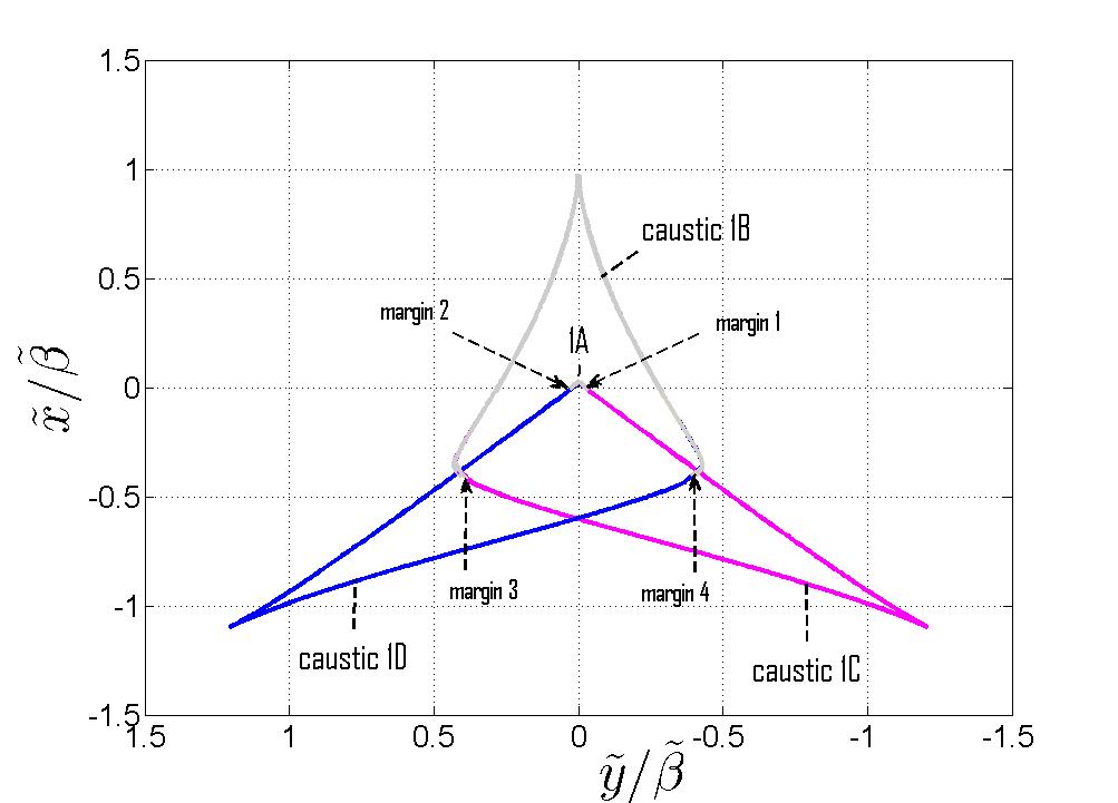
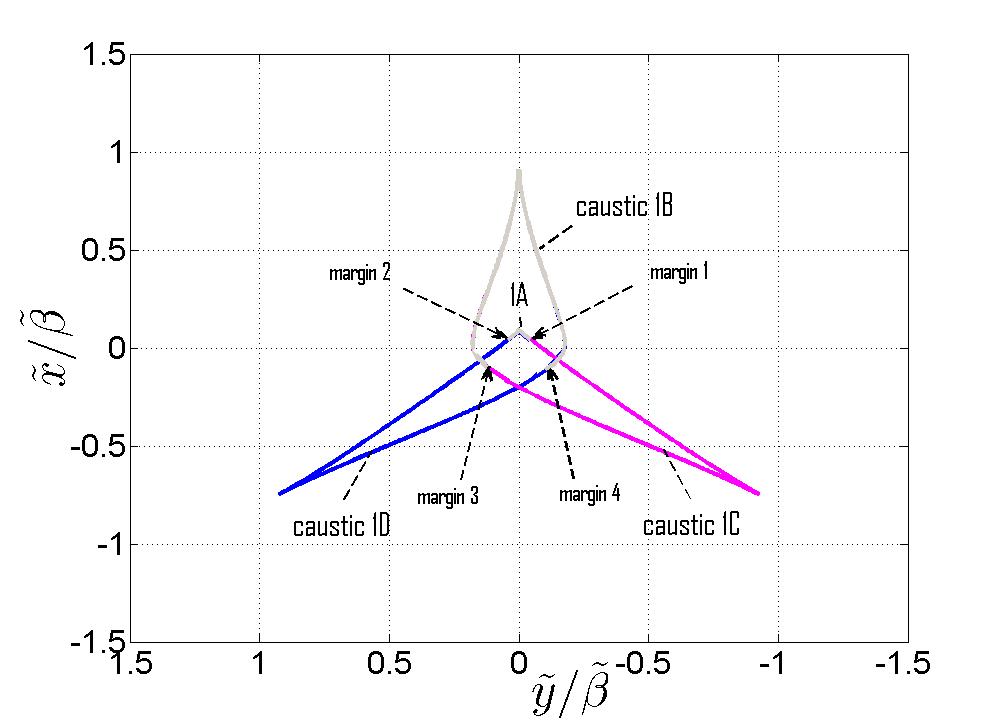
Figs. 14(a) and 14(b) depict the complete structure of caustic 1 as a zoom-out view of Fig. 5, with Fig. 14(a) showing the caustic parts formed by ray species (see Fig. 2 for the species definition), and Fig. 14(b) showing the rest of the caustic. The surfaces in Figs. 14(a) and 14(b) are connected at the margins that are delineated in the figures. The connections of these surfaces are clarified in Fig. 15 which depicts cross-sectional views of the complete caustic at two constant- planes. A cross sectional view in the symmetry plane is depicted in Fig. 16.
As can be discerned from Fig. 14(a), the part of caustic 1 that is shown in Fig. 5, tagged here as “caustics 1A”, is connected to a hat-like structure, tagged as “caustic 1B.” The latter is formed by rays of species 1 exiting the aperture from far away points, as in the case of caustic 2B of Fig. 13. Caustic 1B is a cuspoid (as may also be seen in Fig. 15) with its edge in the plane (red dashed line in Fig. 14(a)).
6.C Discussion: Limitations of the AiB Solution
As discussed in Sec. 3.B, the AiB has been identified as a hyperbolic umbilic diffraction catastrophe. However, as can be seen from Figs. 13-14(a), near the termination point of caustic 2, the hyperbolic umbilic caustic is no longer isolated, and the caustic structure evolves into the more complex parabolic umbilic catastrophe [24, Fig. 7.3]. From this global analysis it then follows that the propagation range of the AiB is limited to the termination point of caustics 2A (see also Fig. 16) where the AiB loses its beam shape. The maximal propagation range is of order and hence it can be controlled by choosing for a desired application. The range is also controlled by which controls the decay rate along the beam axis (see Eqs. (56) and (50)).
The exact ray-based solutions of Secs. 4 and 5 may be used up to the maximal propagation range discussed above. In the near zone, one may also use the PE solution in Eqs. (2)–(3), but the accuracy of this solution reduces as the distance between the exact and the PE approximated caustics grows (see Fig. 6), giving rise to the translational error of the PE field in Fig. 12.
6.D Comments on the Range Limitations of the 2D AiB
In [11] and[16] it has been shown that the 2D-AiB is supported by a smooth caustic which is a fold catastrophe [28]. Those references, however, have concentrated on the field near the beam axis. A global analysis reveals that this 2D caustic is actually a cusp whose form is very similar to the cross section of caustic 2 in Fig. 16 (caustic 1 does not exist in the 2D case). This global structure was not discussed in [11] and [16] since the rays forming the missing parts have weak contributions and late arrival times beyond the pertinent time window [16]. The analysis in Sec. 6.C regarding the limitations of the AiB can be similarly applied to the 2D case.
7 Conclusions
We presented a wave-theoretic analysis of the 3D-AiB and derived uniform solutions for the transition layer near the propagation axis. The formulation is based on exact spectral and ray representations and therefore does not suffer from the limitations of the conventional PE approximation. As in the 2D-AiB case, the 3D-AiB is described by sideways radiating rays that focus onto a caustic that delineates the beam trajectory. However, the 3D ray topology is considerably more complicated than the 2D topology, and it has many intricate features. Specifically, near the curved beam axis, the ray topology of the 3D-AiB consists of a cusped double-layered caustic identified as the hyperbolic umbilic catastrophe (Sec. 3). At a certain range away from the aperture, the hyperbolic umbilic caustic is no longer isolated and evolves into the more complex parabolic umbilic caustic, where the AiB loses its beam shape.
To clarify these issues we have investigated the ray topology of the 3D-AiB using the exact spectral representation for the AiB. We concentrated first on the region near the curved beam axis (Sec. 3), but we have also explored the global caustic topology (Sec. 6). Specifically, we have thoroughly explored all the ray paths that form the double-layered hyperbolic umbilic caustic noted above (Figs. 7–10). These contributions are essential in order to understand the time-dependent Airy pulsed beam (AiPB) that will be presented in a subsequent publication [21].
The field calculations in Secs. 4–5 were based on an asymptotic evaluation of the exact spectral integral of the AiB. In order to calibrate the final results, we derived first the lowest order geometrical optics (GO) solution (Sec. 4.B) which, however, fails near the beam axis. The field near the beam axis has been considered separately in Sec. 5 within the framework of catastrophe theory [27, 28, 24]. As discussed in the introduction (see also Sec. 5), a globally uniform field solution can be obtained via the procedure in [30, Sec. 5]. This approach, while very elegant and systematic, leads to implicit representations where the field is described in a generalized coordinate system that has to be calculated numerically. We therefore used in Sec. 5.A an alterative local approach where the spectral integral of the AiB has been approximated near the caustic using a local coordinate system, and the final result has been expressed as a canonical hyperbolic-umbilic diffraction integral [29, Sec. 36.2]. This more direct approach does not have the global uniformity of the general implicit procedure in [30], yet it has led to a solution that is expressed explicitly in the local coordinate system of the caustic, where all the field parameters are expressed in terms of the geometrical parameters of the caustic and of the aperture field distribution. This solution is valid in the transition layer near the caustic and reduces correctly to the GO field away from the caustic, but far away, one has to switch to the GO field of Sec. 4.B noted above. Using this approach we also modified the hyperbolic-umbilic integral by introducing a complex loss parameter that describes the finite energy AiB.
The final field solution in Eqs. (56) with (32) and (54)) provides an explicit solution in the transition layer near the beam axis. The width of the transition (or boundary) layer is of order (see , coordinates in Eq. (44)) where is the wave-number and is a frequency-independent parameter describing the beam geometry (see Eq. (10)). The caustic topology is controlled by the dimensionless parameter of Eq. (46) appearing in of Eq. (54). This parameter represents the normalized distance between the two layers of the hyperbolic umbilic caustic, scaled with the normalized frequency like . As grows with the observation range , the structure of the boundary layer field described by the canonical integral becomes more complex while for , the two layers are separable and the field can be described by separate cusp and fold catastrophes, as discussed after Eq. (46).
The canonical hyperbolic umbilic integral can be evaluated efficiently via contour deformation in the complex plane. Here, however, we calculated it using the series expansion of [29, Sec. 36.8] which has been modified to accommodate the finite energy AiB (Sec. 5.C). We used it to calculate the field near the beam axis under several parameter regimes (Sec. 5.D). The accuracy of the canonical integral has been demonstrated by noting in Fig. 11 that away from the beam axis it reduces to the GO field (the GO field near the hyperbolic umbilic caustic is a sum of four rays). Far away from the transition layer, however, the field is described more accurately by the GO solution of Sec. 4.B, since it is structured upon the exact ray skeleton and not on the local ray skeleton near the beam axis used here for the construction of the transition function (note that the solutions obtained via the globally uniform approach in [30, Sec. 5] reduce correctly to the GO field even very far from the transition layer, yet, as noted earlier, these solutions are implicit functions of the space coordinates). Comparing the canonical integral to the conventional PE solution one observes in Fig. 12 a significant translational error of the latter which is due to the error of the PE approximated beam trajectory. This error is parameterized by the dimensionless parameter of Eq. (62) which describes the distance between the exact and the PE caustics. grows with (see Figs. 4 and 6) and scales with the normalized frequency like . As discerned from Figs. 11–12, the error is small for , but it becomes significant for .
In summary, it has been demonstrated that the local canonical integral in conjunction with GO provides an accurate and convenient solution to the AiB, as an alternative to the conventional PE solution. This solution is structured upon the exact ray skeleton and therefore has a wider validity range than the PE solution. Furthermore, this solution provides a convenient design tool for synthesizing other types of beams propagating along any prescribed convex trajectory in uniform or non uniform medium. An application of this idea in 2D configurations has been presented in [15].
The analysis in this work has been performed within the framework of the non-dispersive AiB where the aperture field is scaled with frequency such that the ray skeleton is frequency-independent. We use the non-dispersive formulation because it simplifies the ray analysis by making it more transparent geometrically. Moreover, this formulation also extends the AiB solution to the ultra wide band (UWB) frequency regime by ensuring that the pulsed field propagates along the curved beam trajectory without dispersion. This non-dispersive formulation will be used in a subsequent publication [21] to introduce a new class of 3D Airy pulsed beams (AiPB).
A Appendix A: Derivation of the GO Field from the Spectral Representation
In Sec. 3 we introduced the ray representation of the AiB based on the approximate initial field distribution in Eq. (15). In this appendix we derive the ray representation based on the exact spectral representation of the initial field distribution in Eq. (24), and show that the results are the same as those of Sec. 3.
As discussed in Eq. (15), is relatively small and hence we consider first the ray and caustic equations for (Secs. A.1–A.3) and then we consider the GO field for the case (Sec. A.4).
A.1 The Ray Equation
We start by deriving the ray equation in Eq. (11) from the saddle point condition of the exact spectral representation in Eq. (24).
Substituting the spectral delay function of Eq. (25) with into the saddle points condition in Eq. (26) we obtain
| (A.1) | |||
| (A.2) |
where is defined in Eq. (13). For , Eqs. (A.1)–(A.2) reduce to
| (A.3) | |||
| (A.4) |
where are the coordinates in the plan. The right hand side in Eqs. (A.3)–(A.4) is obtained by using Eq. (22) for and it is identical to Eq. (18) for the ray exit angles. Substituting the left hand side of Eqs. (A.3)–(A.4) back into Eq. (A.1)–(A.2) and rearranging, we obtain
| (A.5) | |||
| (A.6) |
which are, in fact the expressions for the ray trajectories in Eq. (11) with . It follows that the ray skeleton derived in Sec. 3 using the approximation in Eq. (14) is the same as the one derived here from the exact spectral representation.
A.2 Ray and Caustic Topology - Exact Analysis
There are two alternative routs to derive the expression for the caustic of Sec. 3. The first is to calculate of Eq. (19) using the ray trajectories in Eq. (11), and then to solve for its zeros. The second relies on the spectral formulation of Sec.4.A. Here we start with the latter since it also complies with the formalism of catastrophe theory which is discussed in Sec. 5.
To calculate the caustic surface we note that the elements of the Hessian matrix in Eq. (28) are given by
| (A.7) | |||
| (A.8) | |||
| (A.9) |
and hence, the determinant is given by
| (A.10) | |||
| (A.11) | |||
| (A.12) |
At the caustic, two or more rays (saddle points) coalesce, implying that there. This equation should be solved in conjunction with Eqs. (A.1)–(A.4) since the caustic is composed of rays. From Eq. (A.10) a ray with parameters is tangent to the caustic at two points
| (A.13) |
The coordinates of these points are found by substituting Eq. (A.13) back into Eqs. (A.1)–(A.2).
As shown in Sec. 3 and Fig. 5, the exact caustic topology near the beam axis is composed of two sheets, denotes as caustic 1 and caustic 2. We have also shown in Figs. 7–8 that a ray of species 1 touches caustic 2 first and then touches caustic 1, never touching the caustic again. Thus the “” sign in Eq. (A.13) corresponds to a point on caustic 1 and 2, respectively.
The edges of the caustics in the symmetry plane (see Figs. 5 and 4) are found by setting in Eqs. (A.13) and (A.1)–(A.2). The ) coordinates can be expressed in the following parametric form
| (A.14) | |||
| (A.15) |
where , being the ray-angle with respect to the axis (see Eq. (12)). Alternatively, in Eqs. (A.14)–(A.15) can be expressed as function of
| (A.16) | |||
| (A.17) |
where all square roots taken with a positive real part. At moderate ranges such that these expressions may be approximated by
| (A.18) | |||
| (A.19) |
where we used . The lowest order approximation in Eqs. (A.18)–(A.19) is the PE solution of Eq. (10), hence one finds for a given that (see also Fig. 6).
Finally we note that the same results could have been obtained via the ray-system analysis. The Jacobian in Eq. (20) can be expressed explicitly as
| (A.20) |
where are given in Eqs. (A.11)–(A.12). Comparing Eqs. (A.10) and (A.20), it follows that the zeros of correspond to the zeros of in Eq. (A.13). define the ray lengths to the caustic.
A.3 The Caustic within the Parabolic Equation Approximation
In the paraxial regime one can approximate in Eq. (13) . Substituting in the ray equations (A.1)–(A.2) with (A.3)–(A.4), yields
| (A.21) | |||
| (A.22) |
The solutions of Eq. (A.10) yields two surfaces , given by
| (A.23) | |||
| (A.24) |
which are shown in Fig. 3. These surfaces intersect at the edge which is the beam axis in Eq. (10).
A.4 Details of the Derivation of the GO Field in Eqs. (27)–(31)
The phase term in Eq. (30) is obtained by substituting the ray directions in Eqs. (A.3)–(A.4) (see also Eq. (18)) and the ray equation in Eq. (12) into of Eq. (25).
Next, in order to derive the amplitude term in Eq. (31), we note from Eq. (A.10) and Eq. (A.20) that the determinant of the Hessian and the Jacobian can be cast in the form
| (A.25) |
where and correspond to of Eq. (A.13); are the ray lengths to caustic 1 and 2, respectively.
From Eq. (A.25), the eigenvalues of the Hessian matrix defined in Eq. (29) are given by
| (A.26) |
Thus if the ray has not touched caustic 1 yet, while if it has touched it. Similarly, if the ray has not yet touched or has touched caustic 2, respectively. We also note, by analyzing Eq. (A.13) for using from Eqs. (A.11)–(A.12), that the ray species has ; species have and ; and species has . Combining these results we find that of Eq. (29) can be written as
| (A.27) |
where is specified after Eq. (17) and is the Maslov index defined after Eq. (31) that counts the number of times that the th ray has touched a caustic.
A.5 Finite Energy AiB ()
For the saddle points are complex and are given by Eqs. (A.1)–(A.4) with and in Eqs. (A.3)–(A.4) replaced by and , respectively. Since is small, the solution for the complex saddle points is very close to the real saddle points obtained for . Therefore, we expand in Eq. (A.1)-(A.2) to first order about
| (A.29) |
where , , , all taken at , and are given by
| (A.30) |
Substituting into Eqs. (A.1)–(A.2) and solving for the saddle points yields
| (A.31) |
Substituting Eq. (A.31), and (A.29)–(A.30) into of Eq. (25), using Eqs. (11) and (A.3)–(A.4) and neglecting terms and lower, we obtain
| (A.32) |
is the expression in Eq. (30). The term in Eq. (A.32) appears inside the exponent in Eq. (17) where it is interpreted as a factor in the initial amplitude rather then a complex time delay. In the expression for the Hessian we neglect so Eq. (A.28) is without change.
B Appendix B: Additional Canonical Form for the Hyperbolic Umbilic Catastrophe
In order to prevent possible confusion we note that the Hyperbolic Umbilic catastrophe has another canonical form in addition to the one in Eq. (42), which has the following form [29, Sec. 36.3, Eq. (3)],[36, pp. 37]
| (B.1) |
This form is obtained from Eq. (42) by using the following transformations
| (B.2) | |||
| (B.3) | |||
| (B.4) |
where and are defined in Eqs. (44)–(46), are defined in Eq. (45), and is given in Eq. (7). Note that some terms which do not depend on have been omitted since they do not affect the catastrophe type.
References
- [1] G. Siviloglou, J. Broky, A. Dogariu, and D. Christodoulides, “Observation of accelerating Airy beams,” Phys. Rev. Lett. 99, 213901–1–213901–4 (2007).
- [2] G. Siviloglou and D. Christodoulides, “Accelerating finite energy Airy beams,” Opt. Lett. 32, 979–981 (2007).
- [3] M. Bandres and J. Gutiérrez-Vega, “Airy-Gauss beams and their transformation by paraxial optical systems,” Opt. Express 15, 16719–16728 (2007).
- [4] G. Siviloglou, J. Broky, A. Dogariu, and D. Christodoulides, “Ballistic dynamics of Airy beams,” Opt. Lett. 33, 207–209 (2008).
- [5] J. Broky, G. Siviloglou, A. Dogariu, and D. Christodoulides, “Self-healing properties of optical Airy beams,” Optics Express 16, 12880–12891 (2008).
- [6] J. Baumgartl, M. Mazilu, and K. Dholakia, “Optically mediated particle clearing using Airy wavepackets,” Nat. Photonics 2, 675–678 (2008).
- [7] S. Vo, K. Fuerschbach, K. Thompson, M. Alonso, and J. Rolland, “Airy beams: a geometric optics perspective,” JOSA A 27, 2574–2582 (2010).
- [8] Y. Gu and G. Gbur, “Scintillation of Airy beam arrays in atmospheric turbulence,” Opt. Lett. 35, 3456–3458 (2010).
- [9] P. Polynkin, M. Kolesik, J. V. Moloney, G. A. Siviloglou, and D. N. Christodoulides, “Curved plasma channel generation using ultraintense Airy beams,” Science 324, 229–232 (2009).
- [10] T. Ellenbogen, N. Voloch-Bloch, A. Ganany-Padowicz, and A. Arie, “Nonlinear generation and manipulation of Airy beams,” Nature Photonics 3, 395–398 (2009).
- [11] Y. Kaganovsky and E. Heyman, “Wave analysis of Airy beams,” Opt. Express 18, 8440–8452 (2010).
- [12] C. Chester, B. Friedman, and F. Ursell, “An extension of the method of steepest descents,” in “Proc. Cambridge Philos. Soc,” , vol. 53 (Cambridge Univ Press, 1957).
- [13] D. Ludwig, “Wave Propagation Near a Smooth Caustic,” Bull. Amer. Math. Soc 71, 776–779 (1965).
- [14] Y. Kravtsov, “A modification of the geometrical optics method,” Izv. VUZ Radiofiz. Engl. transl., Radiophys. Quantum Electron. 7, 664–673 (1964).
- [15] E. Greenfield, M. Segev, W. Walasik, and O. Raz, “Accelerating light beams along arbitrary convex trajectories,” Phys. Rev. Lett. 106, 213902 (2011).
- [16] Y. Kaganovsky and E. Heyman, “Airy pulsed beams,” J. Opt. Soc. Am. A 28, 1243–1255 (2011).
- [17] P. Saari, “Laterally accelerating Airy pulses,” Opt. Express 16, 10303–10308 (2008).
- [18] E. Heyman, and L. B. Felsen, “Weakly dispersive spectral theory of transients (STT), Part I: Formulation and interpretation,” IEEE Trans. Antennas Propagat. 35, 80–86 (1987).
- [19] E. Heyman, and L. B. Felsen, “Weakly dispersive spectral theory of transients (STT), Part II: Evaluation of the spectral integral,” IEEE Trans. Antennas Propagat. 35, 574–580 (1987).
- [20] E. Heyman, “Weakly dispersive spectral theory of transients (STT), Part III: Applications,” IEEE Trans. Antennas Propagat. 35, 1258–1266 (1987).
- [21] Y. Kaganovsky and E. Heyman, “Wave analysis of 3D Airy Pulsed beams,” in preparation for JOSA A.
- [22] H. Trinkaus and F. Drepper, “On the analysis of diffraction catastrophes,” Journal of Physics A: Mathematical and General 10, L11 (1977).
- [23] M. Berry and C. Upstill, “Catastrophe optics: Morphologies of caustics and their diffraction patterns,” Progress in optics 18, 257–346 (1980).
- [24] J. Nye, Natural focusing and fine structure of light: Caustics and wave dislocations, (Institute of Physics Pub., 1999)
- [25] J. Nye, “Dislocation lines in the hyperbolic umbilic diffraction catastrophe,” Proceedings of the Royal Society A: Mathematical, Physical and Engineering Science 462, 2299 (2006).
- [26] M. Berry and C. Howls, “Axial and focal-plane diffraction catastrophe integrals,” Journal of Physics A: Mathematical and Theoretical 43, 375206 (2010).
- [27] T. Poston and I. Stewart, Catastrophe theory and its applications, vol. 2 (Dover Pubns, 1996).
- [28] Y. A. Kravtsov and Y. I. Orlov, Caustics, Catastrophes and Wave Fields (Springer-Verlag, 1993).
- [29] Digital Library of Mathematical Functions (National Institute of Standards and Technology, http://dlmf.nist.gov, 2011).
- [30] M. Berry, “Waves and Thom’s theorem,” Advances in Physics 25, 1–26 (1976).
- [31] N. Bleistein, “Uniform asymptotic expansions of integrals with many nearby stationary points and algebraic singularities,” J. math. Mech 17, 533–559 (1967).
- [32] J. Duistermaat, “Oscillatory integrals, lagrange immersions and unfolding of singularities,” Communications on Pure and Applied Mathematics 27, 207–281 (1974).
- [33] M. Berry, “Cusped rainbows and incoherence effects in the rippling-mirror model for particle scattering from surfaces,” Journal of Physics A: Mathematical and General 8, 566 (1975).
- [34] L. B. Felsen and N. Marcuvitz, Radiation and Scattering of Waves, IEEE Press Series on Electromagnetic Waves (The Institute of Electrical and Electronics Engineers, New York, 1994).
- [35] R. Gilmore, Catastrophe theory for scientists and engineers (Dover Pubns, 1993).
- [36] Y. A. Kravtzov and Y. I. Orlov, Geometrical Optics of Inhomogeneous Media, vol. 6 of Springer Ser. Wave Phenomena (Springer-Verlang, Berlin Heidelberg, 1990).
