A geometric approach to the precession of compact binaries
Abstract
We discuss a geometrical method to define a preferred reference frame for precessing binary systems and the gravitational waves they emit. This minimal-rotation frame is aligned with the angular-momentum axis and fixes the rotation about that axis up to a constant angle, resulting in an essentially invariant frame. Gravitational waveforms decomposed in this frame are similarly invariant under rotations of the inertial frame and exhibit relatively smoothly varying phase. By contrast, earlier prescriptions for radiation-aligned frames induce extraneous features in the gravitational-wave phase which depend on the orientation of the inertial frame, leading to fluctuations in the frequency that may compound to many gravitational-wave cycles. We explore a simplified description of post-Newtonian approximations for precessing systems using the minimal-rotation frame, and describe the construction of analytical/numerical hybrid waveforms for such systems.
pacs:
04.30.-w, 04.80.Nn, 04.25.D-, 04.25.dgI Introduction
One of the central goals of modern numerical relativity is the accurate simulation of compact binary systems, in particular the computation of the gravitational waveforms emitted by these systems. These waveforms provide crucial input into the construction of accurate template banks necessary for detection and parameter estimation based on matched filtering Finn (1992); Finn and Chernoff (1993) in gravitational-wave detectors such as LIGO, Virgo, LCGT Barish and Weiss (1999); Sigg and the LIGO Scientific Collaboration (2008); Acernese et al. (2008); Kuroda and the LCGT Collaboration (2010), and possible space-based detectors such as LISA Prince et al. (2006); Bender et al. (1998); Jennrich (2009). More generally, detailed and accurate knowledge of waveforms provides a dictionary to relate measured waveforms to the specific details of the astrophysical sources that give rise to those waveforms, allowing gravitational-wave experiments to fulfill their proper role as tools for extremely high-precision astrophysics.
For such a bank of gravitational waveforms to be useful, however, it must not be restricted to an astrophysically unrealistic subset of the space of source parameters. Numerical-relativity simulations must eventually treat binary systems with a broad range of mass ratios, spin magnitudes, and spin orientations. Many of the fundamental challenges on the first two points have now been overcome.111See reviews Centrella et al. (2010); McWilliams (2011), as well as Lousto and Zlochower (2011); Lovelace et al. (2011a, b) for simulations that push the limits of large mass ratios and spins. However, precessing binaries remain a formidable challenge. The parameter space of precessing binaries is vastly larger than for non-precessing binaries, and its exploration is just getting underway. Furthermore, the absence of precession allows simplifying assumptions about the properties of the gravitational waveforms, greatly easing post-Newtonian comparisons and simplifying gravitational-wave data-analysis strategies.
When binary systems of black holes (or neutron stars or other compact objects) have spin angular momenta that are misaligned (with one another or with the orbital angular momentum of the pair), the plane of orbital motion inclines and precesses over time. In post-Newtonian theory, this phenomenon can be interpreted as arising from spin-orbit couplings. In fully nonlinear general relativity, these dynamical effects cannot easily be understood in gauge-unambiguous language. However, the effects of this precession can be seen unambiguously in the waveform, as modulations that trade energy content between the various spherical-harmonic modes Apostolatos et al. (1994); Kidder (1995); Gualtieri et al. (2008).
These modulations present difficulties for cataloging the gravitational waveforms. In non-precessing simulations, the standard practice has been to decompose each spherical harmonic component of the waveform into a time-varying amplitude and phase. Both of these elements, in non-precessing cases, can be accurately approximated before or after merger as simple polynomials or exponentially damped polynomials, greatly simplifying their description. In precessing systems, this is no longer the case.
Aside from the complexity of fitting the precessing waveforms, there is also the concern that a precessing system does not have a preferred frame of inertial coordinates. An overall rotation of the inertial coordinates would transform the various waveform modes, modulating them in different ways. This means that comparisons between waveforms must account for a rotation between the inertial frames in which they are measured. In non-precessing cases, this difficulty is avoided by the existence of a preferred, fixed axis (the axis along which the radiation is preferentially beamed). This axis is intuitively associated with the normal to the orbital plane.
Schmidt et al. Schmidt et al. (2011) pointed out that this preferred axis, while no longer fixed in precessing cases, nonetheless still exists and can be used to rotate the inertial spatial coordinates over time, demodulating the waveform. They suggested a method for finding that axis, as did O’Shaughnessy et al. O’Shaughnessy et al. (2011) more recently. Essentially, the idea is to find a rotation operator at each instant in time to maximize the component of the angular momentum in the radiation.222More specifically, the method of Schmidt et al. calls for a rotation that maximizes the power in the modes. However, we show in Sec. II that this can be regarded—in some sense—as a restriction of the method of O’Shaughnessy et al. The axis of the original frame, rotated by this operator, is taken to be the preferred axis. We refer to this axis as the radiation axis.
We expect this insight to be important for understanding and cataloging generic gravitational waveforms. Definition of the radiation axis is the first step toward frames adapted to precessing binaries, in which the gravitational waveforms have simple structure. However, fixing the axis does not fix the frame, because of the ambiguity in rotations about the axis. From a more formal perspective, the (directed) axis being tracked lives in a two-dimensional space: the space of unit vectors in , which is topologically the two sphere . However the space of available rotations, the group manifold of , is topologically , which is three dimensional. In general, no mathematically preferred method exists to infer a unique path in from a path in ; additional conditions must be imposed.
Therefore, the second step toward adapted frames is to fix this rotation about the radiation axis. References Schmidt et al. (2011) and O’Shaughnessy et al. (2011) address the first step by providing suitable definitions of the radiation axis, but deal with the second step only implicitly through the choice of parameterization of the rotation matrices. A rotation around the radiation axis changes the phase of each gravitational-radiation mode by an integer multiple of the rotation angle. An unsuitable choice of this angle will induce unphysical variations in the gravitational-wave phases in the adapted frame, even for vanishingly small precession, as demonstrated in Sec. IV.
The present paper addresses the question of how to fix the rotation about the radiation axis. Our construction is geometric, and the resulting minimal-rotation frame is invariant under rotations of the inertial coordinates in which the precessing waveforms are extracted, except for the remaining freedom of a constant overall rotation. Therefore, the approach proposed here results in an essentially unique adapted frame and in gravitational waveforms that are similarly unique. In contrast, the implementations of Refs. Schmidt et al. (2011) and O’Shaughnessy et al. (2011) choose the final rotation angle in a coordinate-dependent manner: working in terms of Euler angles and always setting the third Euler angle to —by construction, this is the rotation about the axis of the adapted frame.
The key to fixing this remaining freedom by geometric means lies in an analogy with the non-precessing binary. In the non-precessing case, there are again many coordinate frames that preserve the condition that the radiation is primarily quadrupolar with . One could arbitrarily rotate about the axis and preserve this condition. In practice this does not pose a problem, because it is taken as physically obvious that one would not analyze the waveform in a coordinate frame that is rotating about the axis relative to an inertial frame. A fixed overall rotation about the axis is allowed, leading to the well-known overall freedom in the waveform phase. However a time-dependent rotation about the axis, which could cause arbitrary frequency modulation in the waveform, is rejected as unnatural.
Any frame that tracks the radiation axis of a precessing binary, on the other hand, is necessarily changing. As far as possible, we would like to carry over the non-rotating condition from the non-precessing system. In this case, we can describe the rotation of the frame by the instantaneous rotation vector . Relative to an inertial frame, the time derivative of any vector stationary in the rotating frame is given by
| (1) |
If we denote the radiation axis by a unit vector , we see that . Taking the cross product of both sides of this equation with and using the standard triple-product formula, we have
| (2) |
Using the fact that is unit, we can rearrange this as
| (3) |
Of course, the component of along is completely undetermined by this equation; we need some other condition to fix it. Now, when , as in the non-precessing case, we recover the natural non-rotating frame when . This is the same condition imposed by Buonanno, Chen, and Vallisneri Buonanno et al. (2003) in the context of post-Newtonian template waveforms (discussed further in Sec. V.1 below). We stress the importance of this condition more broadly—and particularly in the context of numerical relativity.
Here, we augment the methods of Schmidt et al. and O’Shaughnessy et al. with the condition that the instantaneous rotation of the frame satisfy
| (4) |
Hereafter, we refer to this as the condition of minimal rotation, as this implies that has the smallest possible magnitude, out of the infinitely many rotation vectors consistent with the known motion of the radiation axis. It is significant that this condition on is geometrically meaningful, because is—at any instant—independent of the orientation of the frame in which it is found. As we will demonstrate below, the waveform decomposed in such a frame is independent of an overall rotation, up to a constant phase.
Given a rotation that takes the axis into the radiation axis (), we can use Eq. (4) to find a condition on that holds only if it is a minimal rotation. Alternatively, given any rotation that takes the axis into the radiation axis, we can easily construct another rotation that does the same while also satisfying the minimal-rotation condition. These relations are the key results of this paper.
The remainder of this paper is structured as follows: In Sec. II we summarize the algorithms for finding the radiation axis presented by Schmidt et al. Schmidt et al. (2011) and by O’Shaughnessy et al. O’Shaughnessy et al. (2011). We show that the first method is essentially a restriction of the second, but point out that with slight improvements to the numerical techniques both can be used find the correct radiation axis to very high accuracy—at least for simple toy models in which the correct axis is known. In Sec. III we translate the minimal-rotation condition, Eq. (4), into a condition on the rotation operator itself, and construct a method for imposing this condition while leaving the radiation axis fixed. In Sec. IV, we compare the original algorithms to this coordinate-independent method. First, we show that the motion of the coordinate axes is essentially invariant for our implementation, while the axis motion for the original methods depends sensitively on the orientation of the inertial coordinate frame. We then demonstrate that this dependence shows up in phase the waveform modes using a simple post-Newtonian model. In Sec. V, we exhibit applications of the minimal-rotation frame, which demonstrate that the usual machinery used for non-precessing waveforms can be directly carried over to precessing systems in this frame. In particular, we discuss a framework for calculating post-Newtonian waveforms taking advantage of this simple frame, first proposed by Buonanno, Chen, and Vallisneri Buonanno et al. (2003). We then describe how to compare waveforms and construct hybrids. Finally, in Sec. VI, we close with discussion of the benefits of this method and potential applications in analytic constructions. Two appendices detail our conventions, list some crucial formulas for rotations, and repeat our main results in the language of quaternions.
II Locating the radiation axis
The gravitational waves radiated from a compact binary are typically decomposed in a spin-weighted spherical harmonic expansion of the field on a sphere. For a binary with orbital angular momentum along the axis, the dominant modes in this expansion are the modes. When is not along the axis, however, the various modes will mix, and other modes of the component can dominate. For precessing binaries, this misalignment of the angular momentum and the axis of an inertial frame is inevitable, complicating comparisons between simulations produced with even slightly different initial conditions. Moreover, the amplitude and phase of the modes themselves will become rapidly varying functions of time, complicating analysis of the waveforms. Both of these complications can be eliminated by decomposing the waveform in a non-inertial frame that somehow tracks the motion of the binary. Two methods to do this have been presented in the literature. We now review these, showing that they can be expressed in very similar ways, noting that both can be implemented numerically to achieve very high accuracy, and highlighting the crucial degeneracy present in both.
II.1 The two methods
The first algorithm, presented in Schmidt et al. Schmidt et al. (2011), finds a frame in which the amplitudes of the modes of the gravitational-wave field are maximized. Reference Schmidt et al. (2011) uses the Newman-Penrose Weyl scalar , though the principle is the same for any radiation field—for example, the metric perturbation . We will use the generic symbol to establish the method. We regard as the quantity measured in an inertial frame, and the function under a specified rotation.333To be precise, we define to be the function satisfying , for any angles related by , where each is a rotation operator parameterized by the Euler angles as described in Appendix A. These conventions affect details of later results—for example, the form of Eq. (5) and its independence of (as opposed to ). Each of these can be decomposed in spin-weighted spherical harmonics [Eq. (48)], with weights of the modes denoted and . The relation between and is given by Eq. (49).
The basic idea is to find a rotation to maximize the quantity444For general systems in general orientations, relations like the usual need not hold. As a result, both terms in the sum over are required, to avoid mixing of the modes.
| (5) |
where the are given in terms of the Euler angles by Eq. (44). By considering the relationship between the coordinate systems, Eq. (47), we can see that the radiation axis is given by .
O’Shaughnessy et al. O’Shaughnessy et al. (2011) introduced another method, which finds an axis associated with the quadrupolar part of the radiation field. They begin by defining
| (6) |
where is the usual angular-momentum operator Goldberg et al. (1967), and for simplicity of presentation we set . The radiation axis is then defined as the dominant principal axis of this matrix—the eigenvector with the eigenvalue of largest magnitude. This problem can be solved directly with standard algebraic techniques.
We find it useful to think of this method in a second way. Basic results from linear algebra show us that there exists a rotation operator such that the matrix is diagonal, and that the final column of this diagonalized matrix is the dominant principal axis. To put it another way, then, this method can be regarded as finding a rotation operator that maximizes the - component of the rotated matrix, in which case the radiation axis is just .
The similarity between the two methods becomes clear when we expand this rotated matrix and take the - component:
| (7) |
O’Shaughnessy et al. suggest the possibility of limiting the range of the sum to just . If we further limit the sum to , we have times the quantity given in Eq. (5), and the method of O’Shaughnessy et al. (2011) reduces to that of Schmidt et al. (2011).
Important differences remain between the implementations possible with the two methods, however. When O’Shaughnessy et al. sum over all relevant modes, they are rotating the components of the waveform, which are geometrically meaningful. Thus, the full matrix as they define it is a tensor and therefore obeys standard rotation rules. If we limit the sum over modes, we have a quantity that does not behave properly under rotations. This difference means that can be solved for algebraically in the method of O’Shaughnessy et al., while the method of Schmidt et al. requires a more active maximization procedure.
Nonetheless, we note that the method of Schmidt et al., if implemented carefully, can be made quite accurate and efficient. Because the right-hand side of Eq. (5) (and even its derivatives) can be easily expressed as a known analytic function of the angles , , , the problem is perfectly suited to numerical optimization. We find that it is very easy to implement, with the code converging to the correct radiation axis within roughly , typically using fewer than 10 function evaluations. This method is also quite robust, requiring no initial guess for the radiation axis. The speed and accuracy of this code, then, are essentially the same as the speed and accuracy of code implementing the method of O’Shaughnessy et al.
II.2 Degeneracies
In the discussion above, we glossed over a pair of degeneracies present in both of these methods. The first is trivial: the radiation axis produced by either method is really a directionless axis, rather than the directed axis we have assumed. Roughly speaking, this means that may be either parallel or anti-parallel to the orbital angular momentum. This degeneracy may be resolved by any convenient means, such as comparison with the coordinate angular velocity. In the following, we assume that is chosen to lie parallel to the angular momentum or—at least—points in a consistent direction from moment to moment.
The second degeneracy, however, exhibits a significant flaw in the methods as presented: both are invariant under rotations about the radiation axis, and therefore do not fix the rotation uniquely. We can see this explicitly by looking at the behavior of the modes under such a rotation:
| (8) |
where is the angle of the rotation. Using this in either Eq. (5) or Eq. (6), we see that the phase factor cancels out, leaving no change to the expressions. We need to impose another condition to make these problems well posed. Both Schmidt et al. and O’Shaughnessy et al. break the degeneracy by simply setting the final Euler angle of the rotation to 0. In our conventions, this means setting at all times. But this choice means that the rotation depends on the inertial frame with respect to which the Euler angles are defined. For general precessing systems, it will affect the phase of the final waveform in highly nontrivial ways, as we demonstrate in Sec. IV.2.
Nonetheless, the choice of does make the particular problem of finding the radiation axis well posed. In the next section we take that radiation axis, and use the freedom in to construct a geometrically meaningful frame. This requires abandoning locality in time: while the methods of Refs. Schmidt et al. (2011) and O’Shaughnessy et al. (2011) can be applied for each separately, our method will result in an ordinary differential equation for the rotation matrix.
III Minimizing rotation
The techniques just described give us one particular rotation that aligns the inertial frame with the radiation axis. But the previously noted freedom in means that we can first perform a rotation by an angle about the axis without affecting the radiation axis. We now construct a rotation
| (9) |
and solve for such that the minimal-rotation condition, Eq. (4), is satisfied. The new rotation will simultaneously satisfy the minimal-rotation condition and align the inertial axis with the radiation axis. To find , we express Eq. (4) in terms of the rotation operator alone, making use of generators in the Lie algebra , and various relations noted in Appendix A. We then apply this to the case where is decomposed as in Eq. (9), allowing us to solve for the minimal rotation.
III.1 The minimal-rotation condition in terms of the rotation operator
We begin by defining the equivalents of the instantaneous rotation axis and the radiation axis using the isomorphism which maps 3-vectors into , given in a Cartesian basis by Eq. (34). We write and . Now, the dot product can also be defined for elements of [as times the trace of the product matrix; see Eq. (36)], allowing us to rewrite the minimal-rotation condition as
| (10) |
Here, is unknown, and is time dependent. Therefore, we now translate these into expressions in terms of the rotation operator and the basis element .
The formula for is simple. Recall from Sec. II that . In terms of generators, this is . The formula for can be found by considering Eq. (1), applied to any vector that is stationary in the rotating frame. If we define , we can write in the inertial frame. In , this is written . Then Eq. (1) becomes
| (11) | ||||
| (12) |
where the second line comes from expanding the derivative using Eq. (38). If equality is to hold for arbitrary , we must have
| (13) |
Now, using these expressions for and in Eq. (10) and rearranging a little, we get another form of the minimal-rotation condition:
| (14) |
This is precisely the minimal-rotation condition of Eq. (4) in operator form. We can simplify this expression slightly. Noting that the dot product is invariant under rotations, we apply the inverse rotation to each part of the product, obtaining
| (15) |
III.2 Solving for the initial rotation
To find satisfying the minimal-rotation condition, we now insert Eq. (9) into Eq. (15). Assuming that is known, and using , this will give us a condition on . First, we calculate
| (16) |
Note that conjugation by does not affect the component along . Therefore, plugging this result into Eq. (15) and rearranging, we obtain
| (17) |
Because is known, we can simply evaluate the right-hand side, integrate to find , and insert this back into Eq. (9) to find a minimal-rotation operator that takes the axis into the radiation axis.
We emphasize that the derivations of Eqs. (15) and (17) did not assume any features of and other than the fact that they rotate the axis of the inertial frame into the radiation axis. In particular, we did not assume that the final Euler angle was zero—or indeed use any expression in terms of the Euler angles. Also, though inspired by the Euler angles, the definition is independent of coordinates on .555Note the distinction between the choice of basis for and the choice of coordinates for . Here, the basis produces the canonical basis of generators for by eigenvector problems. In particular, represents the unique generator having eigenvector with eigenvalue 0, and eigenvector with eigenvalue . Also, the exponential function is defined geometrically (see Eq. (33) or Ref. Duistermaat and Kolk (1999)), which shows that is independent of coordinates on . Similarly, the arbitrary choice of axis will not affect the form of these equations; we can choose any unit vector as the axis, and as long as the rotation operators take that vector into the radiation axis, the expressions will not change. Therefore, Eq. (17) is a geometrically general equation: it should hold regardless of any coordinates we might choose for , and should take the same form regardless of the inertial frame we use to find the radiation axis. One result of this is the fact that frames satisfying the minimal-rotation condition are unique up to a constant overall rotation about the radiation axis, corresponding to the integration constant obtained from integrating Eq. (17). We discuss this freedom further in Sec. V.2.
Nonetheless, for the purposes of implementation, an explicit formula involving the Euler angles will be useful. When , a straightforward calculation using Eqs. (39) and (40) gives us666Near the coordinate singularities at and , the value of will contain substantial numerical noise. Differentiating , as in this equation, simply magnifies that noise. For some configurations, we find improved numerical results when integrating this equation by parts and implementing it as .
| (18) |
Schmidt et al. Schmidt et al. (2011) pointed out that the orbital frequency in the rotating frame given by should be roughly (in our notation), where is the magnitude of the orbital frequency measured in the non-rotating frame. Thus our adjustment to their technique can be thought of as removing that second term, so that the orbital frequency in the rotating frame given by should be roughly . We will return to this observation in Sec. V.1 to discuss a simplification of the post-Newtonian representation of precessing systems.
IV The effects of enforcing the minimal-rotation condition
No preferred inertial frame exists for general precessing systems. Indeed, no preferred axis exists for choosing an inertial frame. When the total angular momentum points in a constant direction, this can be a useful choice of axis, but will change direction for inspiralling precessing systems. We might therefore expect data from different numerical simulations, for example, to be presented in different inertial frames. A key concern, then, is the behavior of the rotated frame under fixed rotations of the inertial frame. We now demonstrate that a frame aligned with the radiation axis using behaves poorly under such rotations, whereas such a frame with the minimal-rotation condition imposed is essentially invariant. First, we observe the motion of the rotated axes in the two cases. Then, we inspect the behavior of the phase of the waveform decomposed in the rotating frames.
IV.1 Rotation history in different inertial frames
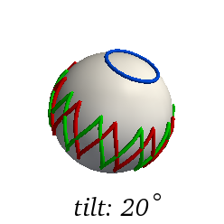
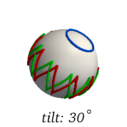
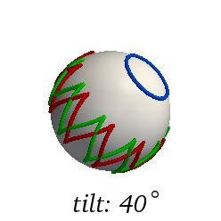
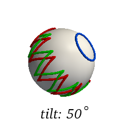
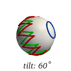
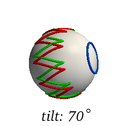
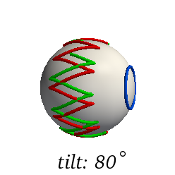
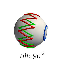
For any rotation , we visualize its “rotation history” by plotting the paths of the tips of the rotated basis vectors, , , and , on the unit sphere. We demonstrate the rotation histories for a toy model in which the radiation axis precesses about a fixed axis , where is inclined to by an angle of . In the first panel of Fig. 1, we show the rotation history for this system when is along the axis and the final Euler angle is simply set to . The blue circle traces the path of the radiation axis—which coincides with the basis vector—while the red and green curves trace the paths of the and axes, respectively.
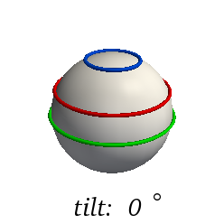
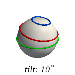
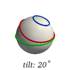
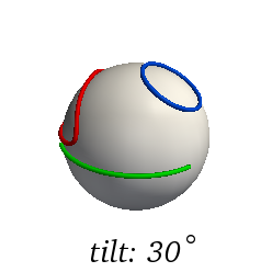
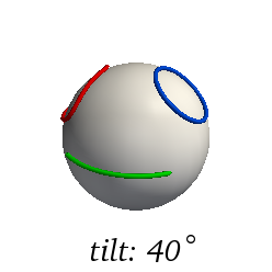
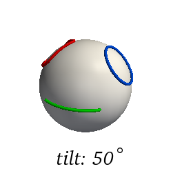
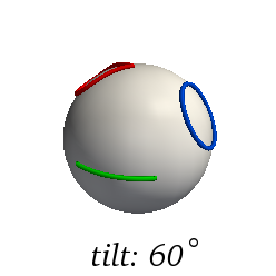
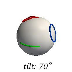
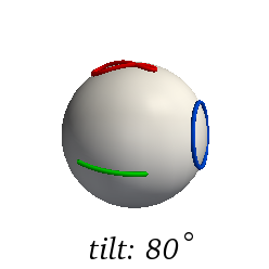
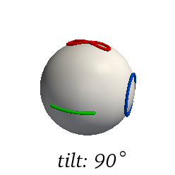
If, instead of being aligned with the axis of the inertial frame, the axis is tipped, we obtain different rotation histories. Later panels of Fig. 1 show the histories when is tilted by the given amount. In each panel, the blue curve remains the same, being simply shifted on the sphere by the given tilt. However, the paths of the other two axes of the adapted frame change drastically as the inclination of is changed, even undergoing topological transitions as this inclination passes the precession inclination and its complement. The tracked frame thus has a time-dependent rotation about the radiation axis, which will show up as a time-dependent modulation of the waveform phase. This modulation is determined by the choice of inertial frame, and therefore the phase of a waveform measured in a frame obtained with is not invariant in any useful sense. This phase modulation will be examined directly in Sec. IV.2.
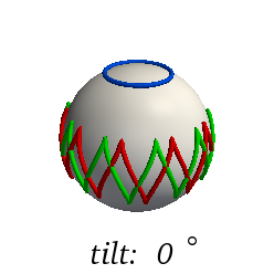
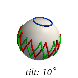
We can repeat this comparison of rotation histories when the third Euler angle is set by the minimal-rotation condition, Eq. (18). The results are shown in Fig. 2. In this case, the rotation histories have the same shapes, but are simply tilted with respect to each other. That similarity shows that frames constructed with the minimal-rotation condition are essentially777There is still an overall freedom in a fixed rotation about the initial radiation axis. This corresponds to the standard ambiguity in orientation, which must be fixed by other methods, discussed in Sec. V.2. invariant under fixed rotations of the inertial frame. As we will now see, the waveform measured in such a frame is similarly invariant.
IV.2 Waveforms in different inertial frames
The methods set forth in Refs. Schmidt et al. (2011) and O’Shaughnessy et al. (2011) fix the axis of the rotated frame in an invariant way, but rely on coordinate-degrees of freedom to fix rotations about that axis. Such a rotation translates directly into the phase of the waveform measured in the rotated frame. Since the minimal-rotation condition is imposed with a rotation about this radiation axis, only the phase of the waveform is affected. Therefore, we ignore the waveform amplitude, as it is invariant as soon as the radiation axis is fixed. We examine the waveform phase with two examples—a simple analytical example first, followed by a more realistic model.
Imagine a system with very small precession, where the radiation axis moves with constant speed along a vanishingly narrow cone centered about the axis. Because the cone is so narrow, we might hope that the phase of the waveform measured in the inertial frame will be close to the phase measured in the rotated frame. Assuming the radiation axis is in the - plane at time , the rotation found by the methods of Refs. Schmidt et al. (2011) and O’Shaughnessy et al. (2011) will be , for constants and . We can relate the modes of the waveform measured in the rotated frame to the modes measured in the inertial frame using Eq. (49b). If we approximate , then the Wigner matrices are nonzero only for , and we have
| (19a) | |||
| That is, the waveform acquires an additional linearly increasing phase in the rotated frame. If the complex phase of this mode is , the change in going from a non-precessing system to a system precessing with a very small opening angle is | |||
| (19b) | |||
Note that the additional phase only depends on the number of times the system has precessed, not the size of the precession angle. If, on the other hand, we impose the minimal-rotation condition, Eq. (18) gives us , which cancels the additional phase, so that . In this sense, the minimal-rotation frame is much more natural.
More importantly, however, a frame with minimal rotation behaves nicely under fixed rotations of the inertial frame. For example, we take the same system as above, but tilt the inertial frame slightly so that the precession cone lies close to, but does not contain the axis. In this case, the rotation will be , where are the usual spherical coordinates of the axis, which we can calculate by simple trigonometry. Using this result to transform the modes, we find
| (20a) | |||
| where is the same constant as above and is a constant that depends on the particular values of the precession and the tilt angles.888In fact, this form of the equation applies for all small precession angles and tilts. If is the tilt angle, then , so corresponds to the case where the precession cone is centered on the axis, and Eq. (20) reduces to Eq. (19). Similarly, corresponds to a small tilt, for which the axis is still within the precession cone. In this case, the additional phase is roughly linear, with a superposed oscillation. corresponds to the case where the radiation axis passes through the axis, which is the coordinate singularity of the Euler angles, meaning that the waveform phase in the frame is actually undefined. Finally, corresponds to a tilt that is larger than the precession angle, so that the axis is not enclosed in the precession cone. In this case, the change to the waveform phase is bounded, but oscillatory: | |||
| (20b) | |||
Thus, a slight change in the inertial frame causes a drastic change in the behavior of the waveform modes, which is associated with the topological change seen in Fig. 1 when the tilt exceeds . In the minimal-rotation frame, on the other hand, the phase change in Eq. (20a) is counteracted by the adjustment to , and we still have .

These features also show up in systems with significant precession. We now turn to a post-Newtonian model of such a binary. The system we choose has equal-mass black holes, with spins initially parallel to each other and orthogonal to the orbital angular momentum, which initially coincides with the axis. The precession cone has an opening angle of roughly initially, gradually widening to about . Using the post-Newtonian waveform, we can the find the radiation axis with the methods described in Sec. II, then decompose the modes of the waveform either in a frame with or in a frame with minimal rotation.
Again, we see the two features identified above. First, the waveform decomposed in the minimal-rotation frame appears to be smoother than the waveform decomposed in the frame. In particular, while the amplitudes are identical in the two frames, the phase of the mode in the frame is constantly increasing relative to the phase in the minimal-rotation frame, and jumps each time the radiation axis passes near the axis (each time is large). We plot the frequency of the mode measured in the two frames in Fig. 3, where the phase jumps show up as spikes.

Second, the waveform phase in the minimal-rotation frame is invariant (up to a constant) under overall rotations of the inertial frame in which the waveform is measured—which is not the case for the frame. We illustrate this by tilting the post-Newtonian system by a rotation about the axis, and redoing the decomposition in the two frames. The frequencies for this rotated system are also plotted (as dotted lines) in Fig. 3, where we see that the curves for the minimal-rotation frame lie on top of each other, while the curve changes but still exhibits spikes.
Figure 4 plots the phase-differences of the (2,2) mode between the two post-Newtonian evolutions differing by a rotation by ,
| (21) |
The minimal-rotation frame is invariant under this rotation, and indeed the phases are identical to within the numerical error (as measured by convergence of the integration of Eq. (18)). The coordinate-dependent choice , however, results in phase differences of multiple gravitational-wave cycles.
While we designed this example to be a rigorous test of the frame-alignment techniques, the later stages of inspiral and merger provide an even more stringent test, as precession frequency scales with orbital velocity. The minimal-rotation condition provides an easily implemented solution to the problems presented by the frame.
V Further applications of the minimal-rotation frame
The minimal-rotation frame aligned with the radiation axis allows us to describe gravitational waveforms from precessing binaries very nicely. The amplitude and phase are smoothly varying functions, and are invariant (up to an overall phase offset) under rotations of the inertial frame. The significance of this construction is broader than one might immediately imagine. We now discuss some of the most important uses of gravitational waveforms, and show that the minimal-rotation frame can make the necessary manipulations much simpler.
V.1 Post-Newtonian waveforms
Buonanno, Chen, and Vallisneri Buonanno et al. (2003) proposed the construction of template waveforms for precessing binaries, expressing the metric perturbation using the minimal-rotation frame (which they simply called the “precessing frame”). Their motivation was to separate the response of a detector into two parts: one describing the intrinsic qualities of the waveform; the other describing the position and orientation of the detector.
This description differs from the more usual approach Apostolatos et al. (1994); Kidder (1995); Arun et al. (2009); Campanelli et al. (2009) of tracking the binary’s orbital parameters in a frame related to the inertial frame by a rotation taking the axis into the Newtonian angular momentum , with the final Euler angle set to . This results in a nontrivial relationship between the orbital frequency in the inertial frame, , and the orbital frequency in the instantaneous orbital plane, :
| (22) |
In such a framework, this equation must be integrated as part of the post-Newtonian system, along with the equations for the angular momentum, spins, and the usual flux and orbital energy, resulting in the motion of the binary as a function of time. This motion is then inserted into expressions for the gravitational waveform in the inertial frame. Because of the complicated motion, these expressions are necessarily even more elaborate than the standard expressions for motion in the orbital plane Arun et al. (2009).
We can substantially simplify the analytical prescription by evolving the orbital elements in the inertial frame, but writing the waveform in terms of spin-weighted spherical harmonics in the rotating frame aligned with the angular momentum Apostolatos et al. (1994). This is particularly easy if the frame satisfies the minimal-rotation condition, Eq. (4). In this case, the instantaneous rotation vector is
| (23) |
Assuming that is given by the angles and , then as in Sec. III.2 we can define the rotating frame by the operator
| (24) |
In such a frame, Eq. (22) becomes
| (25) |
This means that the pN orbital elements can be integrated in the usual way. That is, the orbital phase obtained by integrating the angular frequency is just the phase in the rotating frame. This can then be inserted into the standard expressions Blanchet et al. (2008); Will and Wiseman (1996); Ajith et al. (2011); Arun et al. (2009) for the waveform modes,999This prescription is sufficient at the level of knowledge of post-Newtonian waveforms given in the references. However, by treating the waveform as if it were determined only by instantaneous positions and velocities, it neglects contributions which may be relevant at higher orders. For example, the standard expressions for the waveform amplitudes assume accelerations are orthogonal to the orbital angular velocity, which is not the case for precessing systems. Nonetheless, these contributions can be calculated and projected into the rotating frame. As these are higher-order spinning terms, we ignore them at this level. which gives the waveform in the rotating frame. Together with the rotation operator given by Eq. (24), this describes the waveform completely. In particular, it can readily be transformed to the inertial frame using Eq. (49).
V.2 Comparing waveforms and constructing hybrids
Having obtained some model waveform, one of the first things we typically do is compare the result to some other waveform. For example, we might run a numerical simulation at two different resolutions or using two different numerical codes, and compare the output waveforms to get an estimate for their accuracy. Or we might construct an analytical model, and compare it to a numerical model of the same system. And of course, numerical simulations can only describe the last portion of the inspiral of a binary system, so we frequently combine analytical and numerical waveforms into “hybrid” waveforms. In each of these cases, the first step is to ensure that the two waveforms are expressed in the same coordinate system, which is generally referred to as alignment.
With various simplifying assumptions, alignment boils down to setting the time offset and the relative orientation of the frames in which the waveforms are measured. For a non-precessing binary, as discussed in Sec. I, this further reduces to setting the time offset and a single rotation around the axis. That is, one waveform is adjusted as
| (26) |
for time offset and phase offset . The criteria used to choose those offsets typically ensure that the phase and frequency of are the same in both waveforms at a particular instant, for example.101010Many other possible criteria exist for choosing these offsets (see, e.g., Ref. Boyle (2011)) but the effect on the waveform should always be given by Eq. (26). Therefore we ignore the particular criteria in use.
Precession complicates this simple picture, because we can no longer rotate the second system by just one angle . In general, the inertial frames will be related by some rotation , which rotates the second frame into the first. We would need to solve for this rotation, which might involve rotating the entire component of the waveform to minimize some measure of the difference between the waveforms, for example. This is cumbersome, and would inherently depend on the inertial frame in which the waveforms are measured.
Alternatively, we can measure the two waveforms in minimal-rotation frames aligned with their respective radiation axes. In that case, Sec. IV.2 showed that, again, the only freedom to choose coordinates for the waveforms lies in the time offset and a single phase offset rotating the system about the radiation axis by . This, of course, would not be the case if the frame failed to satisfy the minimal-rotation condition.
These waveforms will also come with rotations and , which describe the orientation of their frames relative to some inertial frames. Again, these inertial frames need not be the same. However, if our criteria for setting the time and phase offsets make the waveforms equal at some fiducial time , we can now directly solve for their relationship:
| (27) |
This value of is then a constant, to be used at all times. More generally, we define a new rotation operator
| (28) |
This operator is more directly comparable to the first rotation operator, in the sense that .
Now, waveform comparisons for non-precessing systems typically measure differences between amplitudes and phases of the aligned waveforms. In precessing systems decomposed in the aligned frame, it makes sense to show the same quantities. However, it is now also important to examine how the frames are aligned as functions of time. The first interesting quantity to compare might be the angle between the two radiation axes, and . A simple formula that expresses this angle is
| (29) |
We also need to understand the relative rotation about the radiation axis, which is particularly important because it translates directly into the phase of the waveform. There is no unique way to define this phase, whenever the two radiation axes are misaligned. In analogy with the above, we might use . However, this can be dominated by the tilt of the radiation axes, so we attempt to remove that part of the rotation. That is, we define the rotation that takes into “directly” by rotating through an angle about the axis . This can be conveniently calculated by the axis-angle formulation or quaternions, as described in Appendix. B. Then, the following fulfills our needs:
| (30) |
These two angles are enough to characterize the misalignment of two frames.
We can also use the aligned frame to construct hybrid waveforms joining analytical and numerical waveforms in the simple manner used for non-precessing systems Boyle et al. (2009). When hybridizing, we use information from only the first waveform before some time , and information from only the second waveform after some time , with some transition in between. This is typically accomplished using a transition function that equals 1 before , 0 after , and transitions smoothly in between. Then, for any quantity , such as the amplitude or phase of a particular mode, we define that quantity in the hybrid as
| (31) |
The same method does not apply trivially when applied to the rotation operators and , but we can suggest a simple method. Various techniques have been developed by researchers in computer graphics to allow interpolation of rotation operators—typically with such unfortunate names as slerp Shoemake (1985), nlerp, and even log-quaternion lerp Grassia (1998). Regardless of the details, any of these can be used to define the interpolant , which equals when and when . We can then define the hybrid rotation operator as
| (32) |
completing the formulation of the hybrid.
VI Discussion
A new element has now been added to the description of a gravitational waveform. The complete description consists of three elements:
-
1.
specification of the inertial frame in which the waveform may be measured,
-
2.
the operator that rotates the inertial frame into the frame in which the modes of the waveform are decomposed, and
-
3.
the modes of the waveform as measured in this rotated frame.
The new element is item 2; previously, the waveform would simply be decomposed in the inertial frame. References Schmidt et al. (2011) and O’Shaughnessy et al. (2011) introduced criteria for choosing such that the amplitudes of the waveform modes become simpler. Our contribution has been the introduction of an additional criterion which simultaneously makes the choice of essentially unique and makes the phases of the waveform modes simpler. Crucially, we developed the simple formula in Eq. (18) for imposing our criterion.
This change to the description of waveforms has many benefits for precessing systems. First, the amplitude and phase of the modes will be more nearly approximated by smooth functions. This means that less storage space will be needed to describe the data from numerical simulations, which is an increasingly important problem in gravitational-wave modeling Ajith et al. (2011). Smooth functions are also crucial to several of the assumptions underlying extrapolation of numerical waveforms to infinite extraction radius, for example Boyle and Mroué (2009). In general, we expect that strong spin-spin couplings will imprint the waveform modes with some non-smoothness, but this method does at least remove the inessential coordinate-dependent features, as illustrated vividly in Figs. 3 and 4.
Second, analysis of the waveforms becomes simpler. The machinery of waveform manipulation for non-precessing systems is well developed. Analytical constructions, methods for comparing waveforms to demonstrate convergence or to measure differences from analytical systems, and hybridization techniques are all broadly understood and applied. The basic approaches, however, are not designed for precessing systems analyzed in an inertial frame; many of the simplifying assumptions break down. The strength of this reformulation to include the rotation operator is that it simplifies the waveform modes, so that we can again use techniques designed for the non-precessing case.
Acknowledgements.
We thank Saul Teukolsky, Larry Kidder, Geoffrey Lovelace, and Serguei Ossokine for helpful discussions, and Richard O’Shaughnessy for pointing out Ref. Buonanno et al. (2003). This project was supported in part by a grant from the Sherman Fairchild Foundation; by NSF Grants No. PHY-0969111 and No. PHY-1005426; and by NASA Grant No. NNX09AF96G. H.P. gratefully acknowledges support from the NSERC of Canada, from the Canada Research Chairs Program, and from the Canadian Institute for Advanced Research.Appendix A Conventions and essential formulas
We begin by briefly reviewing the formalism of rotations of about the origin. Such rotations form a group, described by orthogonal matrices with determinant . The group is denoted , and the group operation is composition of rotations. also forms a manifold satisfying certain consistency properties—it is a Lie group Duistermaat and Kolk (1999). The tangent space to that manifold at the point corresponding to the group’s identity element is called the Lie algebra , consisting of all antisymmetric matrices. This Lie algebra is familiar as the generators of rotations: any gives rise to a rotation via
| (33) |
We also have an isomorphism between (with the matrix commutator as product) and the standard 3-vectors (with the cross product). This map is most easily represented in a standard Cartesian frame, where the vector is mapped as
| (34) |
In particular, we will use the isomorphism relation
| (35) |
for any . We will also use the Cartesian basis for , corresponding to the basis for . We can decompose any element of in this basis by translating the dot product into :
| (36) |
which satisfies . This can be useful as in Eq. (15), for example, where the component along must be taken.
In this context, several formulas will be very useful. For any rotation and vector ,
| (37) |
For any differentiable curve ,
| (38) |
If is a curve such that , then whenever we can calculate
| (39) |
where is the magnitude of the nonzero eigenvalues of , which also equals the vector norm . For any such that , only the first term remains. Finally, for with ,
| (40) |
where is similarly the magnitude of the nonzero eigenvalues of . Obviously, when , only the first term remains.
Euler angles form one convenient set of coordinates for . We define the Euler angles using the -- convention,111111Note that the -- convention is more standard in classical mechanics—as in Ref. Goldstein et al. (2001), for example. The -- convention, however, is more standard when using spherical harmonics, as we do here. where the first rotation is through an angle about the axis, the second through about the (new) axis, and the third through about the (new) axis. Note that this is equivalent to rotations in the opposite order about the fixed set of axes --—which is an especially useful form for calculations. In particular, we can express the rotation operator as
| (41) |
Note that, in this convention, the singularities of the Euler angle coordinates occur when or .
The Wigner matrices form a representation of the rotation group. That is, we know that a composition of rotations in given by
| (42) |
implies the relation
| (43) |
We can find an explicit formula for the as in Ref. Wigner (1959) which, in our conventions, gives
| (44) |
Goldberg et al. Goldberg et al. (1967) showed that the spin-weighted spherical harmonics Newman and Penrose (1966) are simply special cases of this expression. Adopting conventions to agree with Ref. Ajith et al. (2011), we have
| (45) |
Combining Eqs. (43) and (45), we can immediately obtain the transformation law for the spherical harmonics under rotation of the coordinates Boyle (2008):
| (46) |
for angles satisfying
| (47) |
Note that the rotation is uniquely fixed by this condition in a way that it would not be by simply requiring the point defined by to rotate into the point defined by . The fact that such a condition on the coordinates would not uniquely define is the central problem addressed by this paper.
We decompose a function of spin weight as
| (48) |
We then define the rotated function satisfying , where the angles are again related by Eq. (47). We can decompose into spin-weighted spherical harmonics in , and use Eq. (46) to find the relations between the components:
| (49a) | |||
| or equivalently | |||
| (49b) | |||
These relations are special cases of more general transformations derived by Gualtieri et al. Gualtieri et al. (2008).
Appendix B Main results in quaternion form
Another useful parameterization of the rotation group is given by the set of unit quaternions, which are useful as an efficient numerical method for representing rotations. Here, we repeat the main results of this paper (the minimal-rotation condition and a method for imposing it) in the form of quaternions. We also express the Wigner matrices as functions of a quaternion, instead of Euler angles.
Quaternions may be thought of in many ways, but the form we find convenient here is that of a scalar plus a vector. The notation we use will be , where is the scalar part, is the vector part, and are the Cartesian components of the vector. The conjugate of the quaternion is . The distinctive feature of quaternions is their unusual multiplication rule:
| (50) |
Note that this product is associative (unlike the vector cross product) but is neither commutative nor anti-commutative for general quaternions. The unit quaternions satisfy , and can be thought of as points on the unit 3-sphere. The set of all unit quaternions forms a group locally isomorphic to , where rotation of a vector by the unit quaternion can be expressed by
| (51) |
In fact, the quaternions provide a double cover of , as can be seen above by the fact that and produce the same rotation, but this does not cause any practical problems. The relationship with the axis-angle formulation of rotations is particularly clean: for a rotation through an angle about an axis , the quaternion is given by . In any case, we may think of a general rotation as being precisely equivalent to some unit quaternion. For further details, we refer to standard texts (e.g., Ref. Doran and Lasenby (2003)).
A calculation very similar to the derivation of Eq. (13) shows us that the instantaneous rotation vector associated to the unit quaternion is given by
| (52) |
If rotates the axis into the radiation axis, , then the minimal-rotation condition given by Eq. (4) can be rewritten as
| (53) |
where the subscript on the left-hand side takes the scalar part of the expression. This equation is equivalent to the condition on the rotation operator itself given in Eq. (15).
As before, we may impose this condition by applying an initial rotation about the axis. Thus, if is any quaternion rotation that takes the axis into the radiation axis, we define the rotation , where is a rotation through an angle about the axis. Then satisfies the minimal-rotation condition if
| (54) |
Again, given the result of some axis-alignment method, we can evaluate the right-hand side, integrate, and construct the total rotation.
Finally, if the result is to be used to rotate modes of a waveform, we need to express the Wigner matrices in quaternion form. This is done most simply by relating the Euler angles to various components of the quaternion, and substituting the results in Eq. (44). We find
| (55) |
This expression can be used in Eq. (49a); for Eq. (49b), should replace in this expression.
References
- Finn (1992) L. S. Finn, Phys. Rev. D 46, 5236 (1992).
- Finn and Chernoff (1993) L. S. Finn and D. F. Chernoff, Phys. Rev. D 47, 2198 (1993).
- Barish and Weiss (1999) B. C. Barish and R. Weiss, Phys. Today 52, 44 (1999).
- Sigg and the LIGO Scientific Collaboration (2008) D. Sigg and the LIGO Scientific Collaboration, Class. Quant. Grav. 25, 114041 (2008).
- Acernese et al. (2008) F. Acernese et al., Class. Quant. Grav. 25, 184001 (2008).
- Kuroda and the LCGT Collaboration (2010) K. Kuroda and the LCGT Collaboration, Class. Quant. Grav. 27, 084004 (2010).
- Prince et al. (2006) T. A. Prince, P. Binetruy, J. Centrella, L. S. Finn, C. Hogan, G. Nelemans, E. S. Phinney, B. Schutz, and LISA International Science Team, in American Astronomical Society Meeting Abstracts, Bulletin of the American Astronomical Society, Vol. 38 (2006) p. 990.
- Bender et al. (1998) P. L. Bender et al., LISA. Laser Interferometer Space Antenna for the detection and observation of gravitational waves, Tech. Rep. (Max-Planck-Institut für Quantenoptik, München, Germany, 1998).
- Jennrich (2009) O. Jennrich, Class. Quant. Grav. 26, 153001 (2009).
- Centrella et al. (2010) J. Centrella, J. G. Baker, B. J. Kelly, and J. R. van Meter, Rev. Mod. Phys. 82, 3069 (2010).
- McWilliams (2011) S. T. McWilliams, Class. Quant. Grav. 28, 134001 (2011).
- Lousto and Zlochower (2011) C. O. Lousto and Y. Zlochower, Phys. Rev. Lett. 106, 041101 (2011).
- Lovelace et al. (2011a) G. Lovelace, M. A. Scheel, and B. Szilágyi, Phys. Rev. D 83, 024010 (2011a).
- Lovelace et al. (2011b) G. Lovelace, M. Boyle, M. A. Scheel, and B. Szilágyi, “Accurate gravitational waveforms for binary-black-hole mergers with nearly extremal spins,” (2011b), arXiv:1110.2229 [gr-qc] .
- Apostolatos et al. (1994) T. A. Apostolatos, C. Cutler, G. J. Sussman, and K. S. Thorne, Phys. Rev. D 49, 6274 (1994).
- Kidder (1995) L. E. Kidder, Phys. Rev. D 52, 821 (1995).
- Gualtieri et al. (2008) L. Gualtieri, E. Berti, V. Cardoso, and U. Sperhake, Phys. Rev. D 78, 044024 (2008).
- Schmidt et al. (2011) P. Schmidt, M. Hannam, S. Husa, and P. Ajith, Phys. Rev. D 84, 024046 (2011).
- O’Shaughnessy et al. (2011) R. O’Shaughnessy, B. Vaishnav, J. Healy, Z. Meeks, and D. Shoemaker, “Efficient asymptotic frame selection for binary black hole spacetimes using asymptotic radiation,” (2011), arXiv:1109.5224 [gr-qc] .
- Buonanno et al. (2003) A. Buonanno, Y. Chen, and M. Vallisneri, Phys. Rev. D 67, 104025 (2003).
- Goldberg et al. (1967) J. N. Goldberg, A. J. Macfarlane, E. T. Newman, F. Rohrlich, and E. C. G. Sudarshan, J. Math. Phys. 8, 2155 (1967).
- Duistermaat and Kolk (1999) J. J. Duistermaat and J. A. C. Kolk, Lie Groups (Springer-Verlag, New York, NY, 1999).
- Arun et al. (2009) K. G. Arun, A. Buonanno, G. Faye, and E. Ochsner, Phys. Rev. D 79, 104023 (2009).
- Campanelli et al. (2009) M. Campanelli, C. O. Lousto, H. Nakano, and Y. Zlochower, Phys. Rev. D 79, 084010 (2009).
- Blanchet et al. (2008) L. Blanchet, G. Faye, B. R. Iyer, and S. Sinha, Class. Quant. Grav. 25, 165003 (2008).
- Will and Wiseman (1996) C. M. Will and A. G. Wiseman, Phys. Rev. D 54, 4813 (1996).
- Ajith et al. (2011) P. Ajith, M. Boyle, D. A. Brown, S. Fairhurst, M. Hannam, I. Hinder, S. Husa, B. Krishnan, R. A. Mercer, F. Ohme, C. D. Ott, J. S. Read, L. Santamaría, and J. T. Whelan, “Data formats for numerical relativity waves,” (2011), 0709.0093v3 [gr-qc] .
- Boyle (2011) M. Boyle, Phys. Rev. D 84, 064013 (2011).
- Boyle et al. (2009) M. Boyle, D. A. Brown, and L. Pekowsky, Class. Quant. Grav. 26, 114006 (2009).
- Shoemake (1985) K. Shoemake, ACM SIGGRAPH Computer Graphics 19, 245 (1985).
- Grassia (1998) F. S. Grassia, Journal of Graphics Tools 3, 29 (1998).
- Boyle and Mroué (2009) M. Boyle and A. H. Mroué, Phys. Rev. D 80, 124045 (2009).
- Goldstein et al. (2001) H. Goldstein, C. P. Poole, and J. L. Safko, Classical Mechanics, 3rd ed. (Addison Wesley, Reading, MA, 2001).
- Wigner (1959) E. P. Wigner, Group theory and its application to the quantum mechanics of atomic spectra (Academic Press, Inc., New York, NY, 1959).
- Newman and Penrose (1966) E. T. Newman and R. Penrose, J. Math. Phys. 7, 863 (1966).
- Boyle (2008) M. Boyle, Accurate gravitational waveforms from binary black-hole systems, Ph.D. thesis, California Institute of Technology (2008).
- Doran and Lasenby (2003) C. Doran and A. Lasenby, Geometric Algebra for Physicists (Cambridge University Press, New York, NY, 2003).