Holographic power-law traps for the efficient production of Bose-Einstein condensates
Abstract
We use a phase-only spatial light modulator to generate light distributions in which the intensity decays as a power law from a central maximum, with order ranging from (parabolic) to . We suggest that a sequence of these can be used as a time-dependent optical dipole trap for all-optical production of Bose-Einstein condensates in two stages: efficient evaporative cooling in a trap with adjustable strength and depth, followed by an adiabatic transformation of the trap order to cross the BEC transition in a reversible way. Realistic experimental parameters are used to verify the capability of this approach in producing larger Bose-Einstein condensates than by evaporative cooling alone.
pacs:
37.10.Jk, 67.85.Hj, 42.40.JvI Introduction
In recent years, several techniques have been developed with the aim of producing arbitrary, time-dependent optical potentials for ultracold atoms. A fast-scanning acousto-optic deflector can “paint” optical potentials with various geometries Henderson et al. (2009); Zimmermann et al. (2011); Schnelle et al. (2008). Alternatively, the diffraction of a laser beam by a spatial light modulator (SLM) can produce both discrete McGloin et al. (2003); Bergamini et al. (2004); Boyer et al. (2006); He et al. (2009); Kruse et al. (2010) and continuous Rhodes et al. (2006); Fatemi et al. (2007); Pasienski and DeMarco (2008); Bruce et al. (2011) holographic traps. Arbitrary trapping potentials are particularly appealing in view of quantum information processing Beugnon et al. (2007); Porto et al. (2003) and quantum simulation with neutral atoms Lewenstein et al. (2007), the study of superfluid flow in engineered waveguides Ramanathan et al. (2011), and for matter-wave interferometry.
To date, whenever light patterns produced with these techniques are used to trap a quantum gas, the experimental sequence requires an additional trap (optical or magnetic), in which laser-cooled atoms are evaporatively cooled to quantum degeneracy before being transferred into the optical potential of choice. This procedure would be significantly simplified if the laser-cooled atoms were trapped directly in a holographic trap and brought to degeneracy via a dynamic transformation of the potential. The required apparatus is also very compact: all that is needed to achieve quantum degeneracy and any subsequent manipulation of the quantum gas in the holographic trap are two crossed laser beams each modulated by an SLM. In this paper we present power-law holographic traps suitable for this purpose, and we devise a sequence comprising a first stage of evaporative cooling, followed by a second stage in which the BEC transition is crossed reversibly by means of a change in trap order, similar to the one described in Pinkse et al. (1997).
The paper is organised as follows: in Sec. II we discuss the method by which one can program an SLM to generate power-law intensity distributions, and show the actual light patterns produced by the physical device. To our knowledge, this is the first time that a linear (order 1) power-law optical trap, analogous to a quadrupolar magnetic trapping potential, is suggested. We demonstrate the feasibility of using a sequence of such light patterns as a time-dependent trapping potential, by verifying that the light level does not fluctuate as the SLM is refreshed. In Sec. III we lay out the adiabaticity conditions, with respect to the atomic motion in the trap, which any sequence must satisfy. Sec. IV details a fast and efficient evaporative cooling by trap deformation, while in Sec. V we analyse the adiabatic transformation of the trap in the vicinity of the BEC transition. We find that a large gain in phase-space density can be achieved during this last stage, with no significant atom loss. This contributes to the overall efficiency of the scheme in terms of the fraction of atoms left at degeneracy.
II Generating Holographic Traps
Using an iterative Fourier transform algorithm and an SLM, we can create arbitrary light patterns, including power-law intensity distributions of order :
| (1) |
Atoms in this light field will, via the AC-Stark effect, experience a conservative trapping potential for :
| (2) |
where is the trap radius and the trap depth Grimm et al. (2000). Here we assume light detuned by from the atomic transition frequency . is the natural linewidth of the atomic transition and is the speed of light.
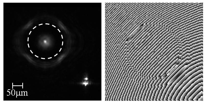
A phase-only SLM consists of an array of liquid-crystal pixels which can be individually oriented. These can be used to manipulate the profile of a laser beam in the far-field by imparting a controlled, spatially-varying retardation on the light. The far-field pattern can also be realized by focusing the phase-modulated laser beam using a lens.
For a given target intensity distribution in the focal plane of the lens, we use the Mixed-Region Amplitude-Freedom (MRAF) algorithm Pasienski and DeMarco (2008) to calculate the optimal phase pattern in the SLM plane. This algorithm performs an optimization procedure on a guess phase pattern, by iteratively transforming the light field between the SLM plane and the focal plane of the lens (i.e. the output plane) by means of Fast Fourier Transforms (FFTs). After each FFT, the desired intensity of the light field is enforced on both planes. In particular, the MRAF algorithm divides the output plane into two regions: a signal region in which we restrict the intensity to match our target pattern, and a noise region in which the intensity is unconstrained. This separation allows for increased accuracy in the signal region. Phase freedom in the output plane is permitted, while the intensity profile in the input plane is that of the laser beam illuminating the SLM. The algorithm allows accurate and fast (a few hundred iterations) calculations of phase patterns to generate almost any arbitrary light pattern in the signal region of the output plane. An example of a phase pattern that generates a power-law intensity distribution of order is shown in Fig. 1.
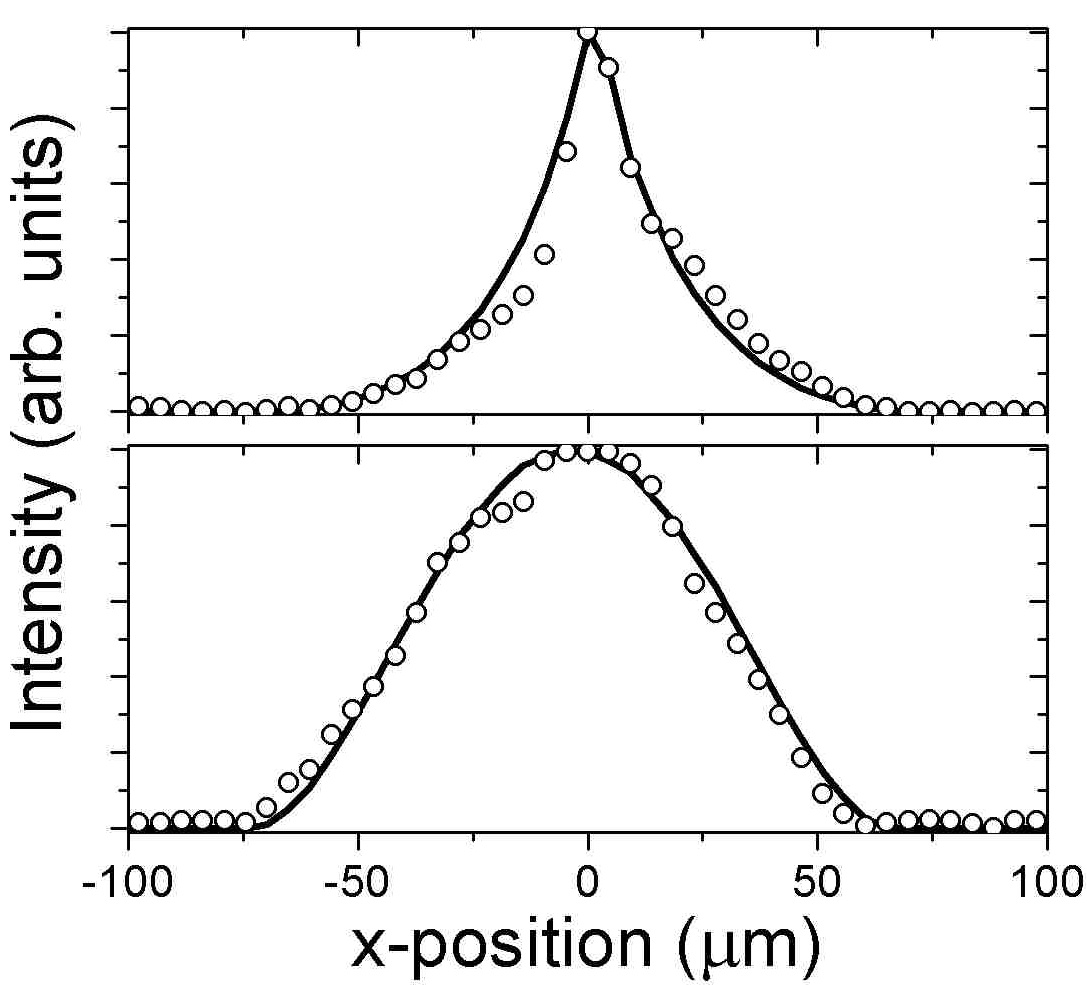
The optimal retardation pattern calculated using the above method is then applied to an SLM (BNS P-256), which contains m nematic liquid crystal pixels. The SLM is illuminated with nm light generated by a diode laser, and the diffracted beam, focused by an mm achromatic doublet lens, is detected by a CCD camera. The MRAF-optimised phase pattern does not always produce an accurate intensity pattern when applied to a physical device, due to imperfect device response and aberrations in the optical system Pasienski and DeMarco (2008); Bruce et al. (2011). However for the case of simple power-law intensity distributions, we have found that the output is smooth and accurate. In particular we have generated power laws with ranging between and . Fig. 1 shows the light pattern in the output plane as detected by the CCD camera, while Fig. 2 shows the intensity profiles of (parabolic) and distributions. At fixed order, we have also varied the radius between m and m. The size of the signal region is chosen so that the uncontrolled intensity in the noise region is well separated from the power-law pattern. This minimises the effect of the noise region on atoms loaded in the power-law trap.
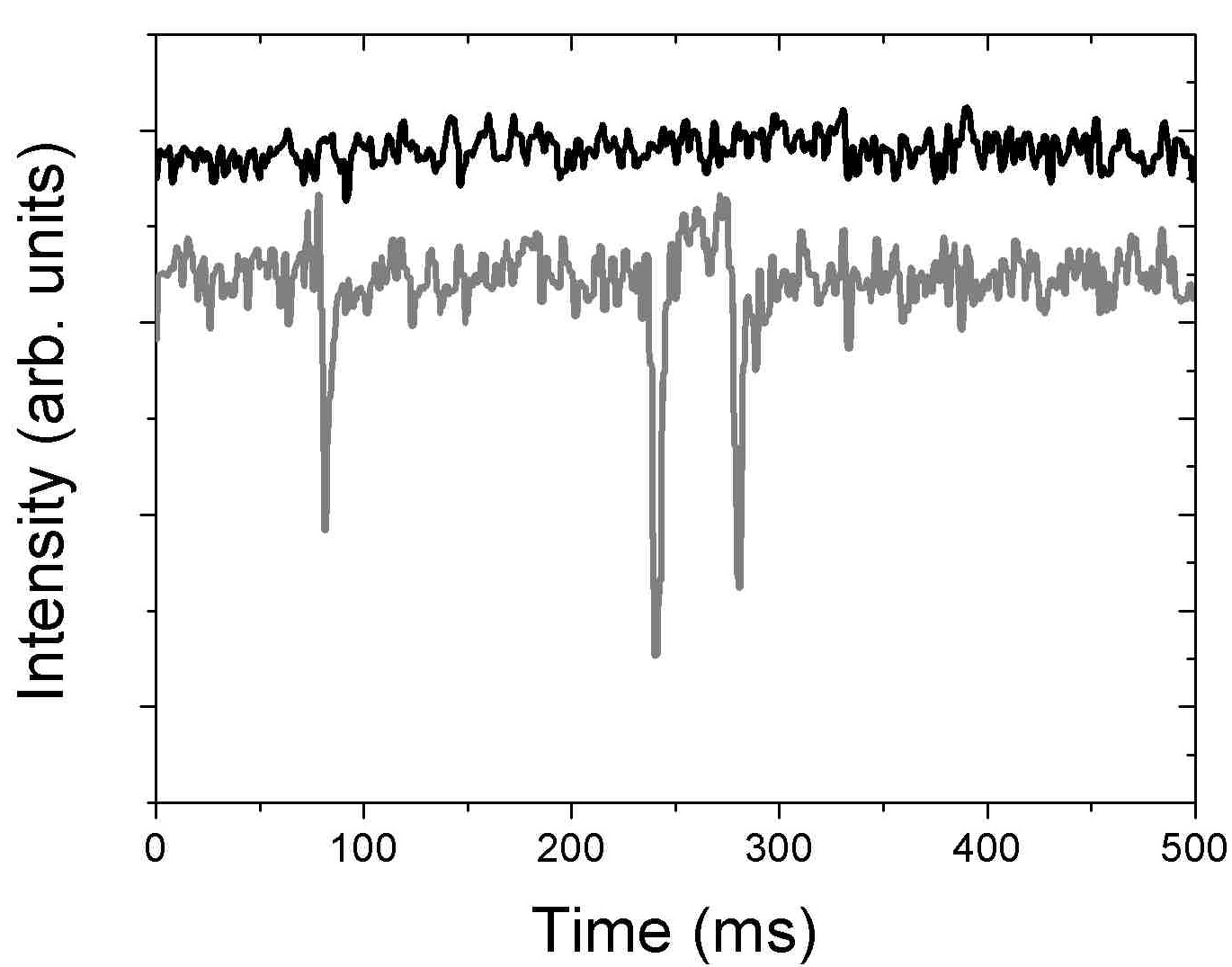
By applying a sequence of phase patterns to the SLM, dynamic optical traps can be generated. It has been noted previously Boyer et al. (2004) that dynamic light patterns generated by ferroelectric liquid crystal SLMs can be subject to substantial intensity flicker due to the changes in the state of individual pixels. We find that this problem also exists in our nematic liquid crystal SLM, but can be solved by careful implementation of the MRAF algorithm. To achieve dynamic power-law optical traps, we apply a sequence of phase patterns producing power laws withr going from to in steps of at Hz. In the lower trace in Fig. 3, intensity flicker occurs when the order changes from to and also to and from order . This is because the initial guess phase used as the input to the MRAF algorithm for orders and happens to be different from the one used for all the other orders. Since the MRAF-optimised phase pattern strongly depends on the initial guess, a significant change is incurred in moving from one of these orders to any of the others. In particular of the SLM pixels change the phase shift they impart to the light, by on average. To overcome this, the retardation patterns are recalculated using the same guess phase for all orders. This results in a sequence in which of pixels change their phase shift at each step, but only by on average. As shown in the upper trace of Fig. 3, we can no longer measure any flicker between consecutive patterns.
To ensure that the two-dimensional intensity patterns generated by the SLM are suitable for three-dimensional optical trapping of cold atoms, we verified that the beam maintains its power-law profile for a propagation of at least m away from the focal plane of the lens. This distance is greater than the width of all the power-law distributions we realised, hence two perpendicular power-law beams, each tailored by an SLM, can provide three-dimensional confinement as discussed later in this paper. Alternatively, a light sheet can be used to add confinement along the axis of the SLM beam.
III Adiabaticity Conditions
In the previous section, we showed that the size and order of a power-law trap can be dynamically varied by refreshing the phase pattern on the SLM. Moreover, the trap depth can be controlled by varying the optical power illuminating the SLM. This gives full flexibility in designing sequences. How fast a sequence can then be implemented is limited by the requirement that changes in the trapping potential must be slow compared to the thermalisation time, which is determined by the elastic collision rate. Additionally, changes must be slow with respect to the motion of the atoms in the trap. In the case of a harmonic trap characterised by a frequency , any compression or expansion of the trap must satisfy Ketterle et al. (1999).
Similarly, in our generic power-law trap such an adiabaticity condition can be formulated for each of the three parameters (radius, depth and order), given that they can be varied independently. The condition therefore is that the relative change of a parameter per unit time be much less than the characteristic oscillation frequency of an atom in the trap. For the traps considered in this work, this is of the order of where is the atomic mass Landau and Lifshitz (1993). Hence the adiabaticity conditions can be written as:
| (3) |
where . The SLM can vary and in small but discrete steps, and it takes ms to change from one pattern to the next, as estimated by the duration of the flicker shown in Fig. 3. For the transformations considered below, , m, and the characteristic oscillation frequencies are several KHz. These parameters ensure that Eq. (3) is satisfied for . The trap depth on the other hand can be varied continuously, hence can be taken as the total change over a sequence, and as the total duration of that sequence. We expect the evaporative cooling sequence and the adiabatic transformation described below to last about one second, for which Eq. (3) is satisfied.
IV Evaporative cooling sequence
In the remainder of the paper, we assume that two power law-shaped laser beams are crossed to form a three-dimensional trap. We assume for simplicity that this trap is spherically symmetric (which can be realized by modifying the aspect ratio of the light distributions shown in Sec. II), but our results are also valid in the case of asymmetric traps as long as the trap order is the same in all directions.
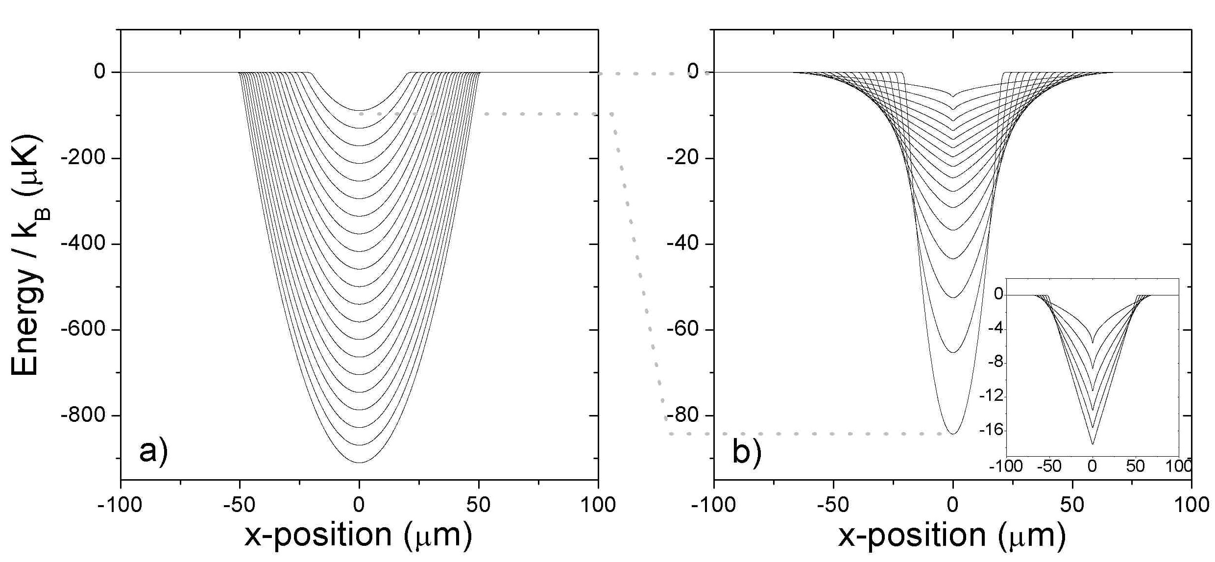
As for any all-optical scheme, our approach is suitable for all internal states, atomic mixtures and molecules. In the following we use 87Rb as an example. Laser-cooled atoms from a magneto-optical trap can be captured into a broad (radius m), K deep parabolic () optical trap. This is the deepest trap shown in Fig. 4a. Following Eqs. (1) and (2), an optical power of W in each beam is needed for such a trap at a wavelength of nm.
From experiments in which similar conditions have been realized in practice Jacob et al. (2011), we take as our starting point atoms with a temperature K, resulting in a phase-space density and an elastic collision rate s-1. This elastic collision rate is sufficiently high that a first stage of adiabatic compression is not necessary. However this could be included (by reducing the trap radius and increasing the depth at constant power) if the starting conditions required it, hence evaporation can be optimized for a broad range of experimental parameters. We note moreover that the chosen initial atom number is conservative, and that increasing the trap size results in more atoms being captured Jacob et al. (2011), ultimately leading to a larger condensate.
A possible evaporation sequence is shown in Fig. 4a. The trap depth is gradually lowered to force evaporation, while the trap radius is adjusted to maintain optimal conditions. In particular, we choose to keep the elastic collision rate constant, as opposed to selecting a sequence of runaway evaporation. Given our starting conditions, this ensures that the atomic number density does not increase to the point where three-body recombination losses become significant. The trap order is kept at 2 because smaller values would result in decreased efficiency of the evaporation process Ketterle and van Druten (1996). The efficiency is defined as:
| (4) |
which is equivalent to , where is the effective volume occupied by the atoms. This relation can be used to express the dependence of on and , which is then substituted in the condition for the elastic collision rate constant. Next we express and in terms of the trap depth and radius respectively: and , assuming the truncation parameter is kept fixed throughout evaporation. The condition for constant finally becomes:
| (5) |
which is used to plot the intermediate steps of the evaporation sequence in Fig. 4a. For this we assume and (i.e. evaporation near stagnation), as typical for evaporation in optical traps O’Hara et al. (2001); Kinoshita et al. (2005); Clément et al. (2009); Jacob et al. (2011). Similarly to these experiments, we expect evaporation to work on timescales of seconds. Hence the SLM needs to be refreshed at a rate less than Hz to produce the intermediate steps. Given that this is much smaller than the characteristic trap frequency, we do not expect significant parametric heating Savard et al. (1997) from residual intensity flicker at the refresh rate.
At the end of the evaporation sequence, the final trap radius and depth are m and K respectively, at which point and atoms remain in the trap. The adiabatic transformation described in the next section is then used to bring the sample to degeneracy.
V Adiabatic Transformations
As shown in Pinkse et al. (1997), the phase-space density of a collisional gas can be increased adiabatically and reversibly, without loss of atoms, by reducing the trap order. This is different from compressing or expanding a trap while keeping the same order, in which case the temperature and the number density change so as to keep the phase-space density constant. In the following, we consider an adiabatic transformation in which the trap order goes from to , starting from the parabolic trap at the end of the evaporation sequence (i.e. the smallest trap in Fig. 4a). We define our transformation such that at the atoms reach the critical temperature for Bose-Einstein condensation, i.e. and .
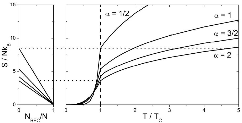
For such a transformation to be reversible, it must be slow compared to the thermalization time. We estimate that the elastic collision rate during our sequence does not drop significantly from the value of s-1 during evaporation, so a sequence lasting about one second (as suggested in Sec. III) satisfies this requirement. We can therefore impose that the entropy is constant during the transformation, with defined by Pinkse et al. (1997):
| (6) |
where is the fugacity with the chemical potential, and . Below , and therefore . Above , we find by numerically solving 111Eq. (7) is obtained from Eq. (4) in Pinkse et al. (1997) at and above .:
| (7) |
This results in the plots of entropy per particle versus shown in Fig. 5 for several trap orders. For the conservation of entropy, the value at the critical temperature for (see upper dotted line in Fig. 5) must also be the entropy per particle at the beginning of the adiabatic transformation, i.e. for . This corresponds to and in the parabolic trap, as achieved at the end of the evaporation. From the conservation of entropy and Eq. (7) we can then determine and for the intermediate steps of the adiabatic sequence.
To calculate the trap depth and size required for this sequence, we start by imposing to avoid further evaporation during the transformation. Secondly, the end point of the sequence is determined by imposing a peak density cm-3, which gives a moderate rate of atom loss due to three-body recombination of s-1 Marte et al. (2002). We then use the critical condition (with the thermal de Broglie wavelength ) to calculate nK in the trap. To find the trap size , we consider the expression for in a generic power-law trap Dalfovo et al. (1999):
| (8) |
and we solve it for to find m. Having fixed the trap parameters at the start and the end of the sequence, we assume for simplicity a linear interpolation for . We use Eq. (8), in conjunction with from entropy conservation, to determine and individually, as shown in Fig. 6. The resulting trap profiles are shown in Fig. 4b.
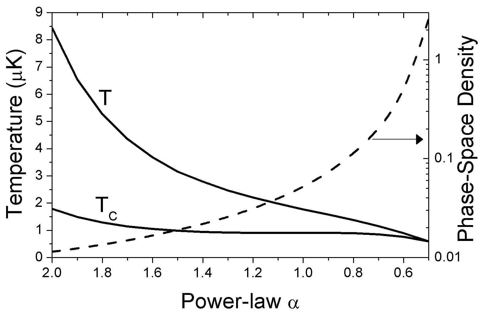
The optical power needed for the final trap () is mW per beam, which is of the power at the start of evaporation. Such a large dynamic range can be achieved by varying the power illuminating the SLM, e.g. with a motorized rotating waveplate followed by a Glan-Taylor polarizer, and by changing the power emitted by the laser Jacob et al. (2011). Towards the end of the adiabatic transformation, the trap is so shallow that the effect of gravity cannot be neglected. It is possible to compensate for it either with a magnetic field gradient, or by designing “tilted” intensity patterns.
We see from Fig. 6 that the adiabatic transformation achieves a significant gain in phase-space density. Intuitively, the gas undergoes an expansion and its temperature decreases. However the change in trap order causes an increase in peak density which is especially pronounced at the end of the sequence. We estimate that only of atoms are lost due to three-body recombination for a sequence that lasts s, which justifies our assumption of constant atom number throughout the adiabatic transformation. In conclusion, about of the laser-cooled atoms loaded into the initial optical trap remain when the sequence terminates at the BEC transition, which is higher than in any other all-optical technique implemented so far.
If evaporation is continued to the BEC transition at the same efficiency assumed in Sec. IV, atoms remain in the trap - which is only of the initial atom number. In this case however the adiabatic change of trap order (see lower dotted line in Fig. 5) provides a new method to cross the BEC transition in a reversible way, similarly to the dimple technique Stamper-Kurn et al. (1998). From the conservation of entropy, we find that varying from to leads to . A condensate fraction is found using Pinkse et al. (1997), as shown in the left side of Fig. 5, hence at the end of the adiabatic transformation. Our sequence could then be combined with in-situ imaging Andrews et al. (1996) to provide a reversible method to investigate the BEC transition.
VI Conclusions
We have used an SLM to holographically generate power-law intensity patterns of different orders and sizes, and we have shown how a sequence of these can be used as a dynamic optical trap for fast and efficient production of Bose-Einstein condensates. Starting from realistic assumptions, we have calculated the trap parameters throughout the sequence. We have also presented the adiabaticity criteria for a generic transformation that goes beyond the standard case of the compression and expansion in a harmonic trap. A future step will be the study of evaporative cooling and adiabatic transformations in more complex trap geometries.
Acknowledgements.
The authors would like to thank Steve Lister, James Mayoh and Tiffany Harte for useful discussions. This work was supported by the UK EPSRC, and GS acknowledges support from a SUPA Advanced Fellowship.References
- Henderson et al. (2009) K. Henderson, C. Ryu, C. MacCormick, and M. G. Boshier, New Journal of Physics 11, 043030 (2009).
- Zimmermann et al. (2011) B. Zimmermann, T. Müller, J. Meineke, T. Esslinger, and H. Moritz, New Journal of Physics 13, 043007 (2011).
- Schnelle et al. (2008) S. K. Schnelle, E. D. van Ooijen, M. J. Davis, N. R. Heckenberg, and H. Rubinsztein-Dunlop, Opt. Express 16, 1405 (2008).
- McGloin et al. (2003) D. McGloin, G. Spalding, H. Melville, W. Sibbett, and K. Dholakia, Opt. Express 11, 158 (2003).
- Bergamini et al. (2004) S. Bergamini, B. Darquié, M. Jones, L. Jacubowiez, A. Browaeys, and P. Grangier, J. Opt. Soc. Am. B 21, 1889 (2004).
- Boyer et al. (2006) V. Boyer, R. M. Godun, G. Smirne, D. Cassettari, C. M. Chandrashekar, A. B. Deb, Z. J. Laczik, and C. J. Foot, Phys. Rev. A 73, 031402 (2006).
- He et al. (2009) X. He, P. Xu, J. Wang, and M. Zhan, Opt. Express 17, 21007 (2009).
- Kruse et al. (2010) J. Kruse, C. Gierl, M. Schlosser, and G. Birkl, Phys. Rev. A 81, 060308 (2010).
- Rhodes et al. (2006) D. P. Rhodes, D. M. Gherardi, J. Livesey, D. McGloin, H. Melville, T. Freegarde, and K. Dholakia, J. Mod. Opt. 53, 547 (2006).
- Fatemi et al. (2007) F. K. Fatemi, M. Bashkansky, and Z. Dutton, Opt. Express 15, 3589 (2007).
- Pasienski and DeMarco (2008) M. Pasienski and B. DeMarco, Opt. Exp. 16, 2176 (2008).
- Bruce et al. (2011) G. D. Bruce, J. Mayoh, G. Smirne, L. Torralbo-Campo, and D. Cassettari, Physica Scripta T143, 014008 (2011).
- Beugnon et al. (2007) J. Beugnon, C. Tuchendler, H. Marion, A. Gaëtan, Y. Miroshnychenko, Y. R. P. Sortais, A. M. Lance, M. P. A. Jones, G. Messin, A. Browaeys, and P. Grangier, Nature Physics 3, 696 (2007).
- Porto et al. (2003) J. V. Porto, S. Rolston, B. L. Tolra, C. J. Williams, and W. D. Phillips, Phil. Trans. R. Soc. Lond. A 361, 1417 (2003).
- Lewenstein et al. (2007) M. Lewenstein, A. Sanpera, V. Ahufinger, B. Damski, A. Sen(De), and U. Sen, Adv. Phys. 56, 243 (2007).
- Ramanathan et al. (2011) A. Ramanathan, K. C. Wright, S. R. Muniz, M. Zelan, W. T. Hill, C. J. Lobb, K. Helmerson, W. D. Phillips, and G. K. Campbell, Phys. Rev. Lett. 106, 130401 (2011).
- Pinkse et al. (1997) P. W. H. Pinkse, A. Mosk, M. Weidemüller, M. W. Reynolds, T. W. Hijmans, and J. T. M. Walraven, Phys. Rev. Lett. 78, 990 (1997).
- Grimm et al. (2000) R. Grimm, M. Weidemüller, and Y. B. Ovchinnikov, in Advances In Atomic, Molecular, and Optical Physics, Vol. 42, edited by B. Bederson and H. Walther (Academic Press, 2000) pp. 95 – 170.
- Boyer et al. (2004) V. Boyer, C. M. Chandrashekar, Z. J. Laczik, and C. J. Foot, J. Mod. Opt. 51, 2235 (2004).
- Ketterle et al. (1999) W. Ketterle, D. S. Durfee, and D. M. Stamper-Kurn, in Bose–Einstein Condensation in Atomic Gases, Proceedings of the International School of Physics “Enrico Fermi”, Course CXL, edited by M. Inguscio, S. Stringari, and C. E. Wieman (IOS Press, Amsterdam, 1999) pp. 67–176.
- Landau and Lifshitz (1993) L. D. Landau and E. M. Lifshitz, Mechanics (Butterworth-Heinemann, 1993).
- Jacob et al. (2011) D. Jacob, E. Mimoun, L. D. Sarlo, M. Weitz, J. Dalibard, and F. Gerbier, New Journal of Physics 13, 065022 (2011).
- Ketterle and van Druten (1996) W. Ketterle and N. J. van Druten, in Advances in Atomic, Molecular, and Optical Physics, Vol. 37, edited by B. Bederson and H. Walther (Academic Press, 1996) pp. 181–236.
- O’Hara et al. (2001) K. M. O’Hara, M. E. Gehm, S. R. Granade, and J. E. Thomas, Phys. Rev. A 64, 051403 (2001).
- Kinoshita et al. (2005) T. Kinoshita, T. Wenger, and D. S. Weiss, Phys. Rev. A 71, 011602(R) (2005).
- Clément et al. (2009) J.-F. Clément, J.-P. Brantut, M. R. de Saint-Vincent, R. A. Nyman, A. Aspect, T. Bourdel, and P. Bouyer, Phys. Rev. A 79, 061406(R) (2009).
- Savard et al. (1997) T. A. Savard, K. M. O’Hara, and J. E. Thomas, Phys. Rev. A 56, R1095 (1997).
- Note (1) Eq. (7) is obtained from Eq. (4) in Pinkse et al. (1997) at and above .
- Marte et al. (2002) A. Marte, T. Volz, J. Schuster, S. Dürr, G. Rempe, E. van Kempen, and B. J. Verhaar, Phys. Rev. Lett. 89, 283202 (2002).
- Dalfovo et al. (1999) F. Dalfovo, S. Giorgini, L. P. Pitaevskii, and S. Stringari, Rev. Mod. Phys. 71, 463 (1999).
- Stamper-Kurn et al. (1998) D. M. Stamper-Kurn, H.-J. Miesner, A. P. Chikkatur, S. Inouye, J. Stenger, and W. Ketterle, Phys. Rev. Lett. 81, 2194 (1998).
- Andrews et al. (1996) M. R. Andrews, M.-O. Mewes, N. J. van Druten, D. S. Durfee, D. M. Kurn, and W. Ketterle, Science 273, 84 (1996).