Dipole coupling of a double quantum dot to a microwave resonator
Quantum coherence in solid-state systems has been demonstrated in superconducting circuits Nakamura1999 and in semiconductor quantum dots Hayashi2003 . This has paved the way to investigate solid-state systems for quantum information processing with the potential benefit of scalability compared to other systems based on atoms, ions and photons natureinsight2008 . Coherent coupling of superconducting circuits to microwave photons, circuit quantum electrodynamics (QED) Wallraff2004 , has opened up new research directions Schoelkopf2008 and enabled long distance coupling of qubits Majer2007 . Here we demonstrate how the electromagnetic field of a superconducting microwave resonator can be coupled to a semiconductor double quantum dot. The charge stability diagram of the double dot, typically measured by direct current (DC) transport techniques kouwenhoven1997 , is investigated via dispersive frequency shifts of the coupled resonator. This hybrid all-solid-state approach offers the potential to coherently couple multiple quantum dot and superconducting qubits together on one chip, and offers a method for high resolution spectroscopy of semiconductor quantum structures.
Semiconductor quantum dots are highly controllable solid-state quantum systems vanderWiel2003 ; Hanson2007 . Charge measurements in the radio frequency (RF) regime have been demonstrated Lu2003 ; Reilly2007 ; Cassidy2007 ; Mueller2010 and recently a lumped element RF resonator was used to measure the quantum capacitance of a double dot Petersson2010 . A number of schemes have been proposed for the scaling of quantum dot based quantum information processing Childress2004 ; Taylor2005 ; Burkard2006 ; Taylor2006 . In this work we implement a form of circuit QED Wallraff2004 , coupling charge states of a double dot to the field of an on-chip microwave transmission line resonator Childress2004 .
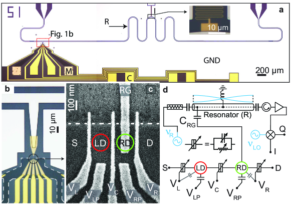
The sample investigated is shown in Fig. 1a-c along with an electrical circuit schematic (Fig. 1d). The microwave resonator (see Fig. 1a) is realized using a thick Aluminum coplanar waveguide on GaAs and is capacitively coupled to an input and output line to probe its transmission spectrum. The double quantum dot (see Fig. 1c), is fabricated at the position of an anti-node of the standing wave field distribution of the resonator. The left and right dots (LD, RD) are arranged in series with respect to the source and drain (S, D) and are realized on an heterostructure with the two-dimensional electron gas (2DEG) at a depth of about below the surface.
To enable a strong coupling between the two systems, an additional gate (RG) (Fig. 1c) was implemented, which extends from the resonator to the right quantum dot. This gives a selective capacitive coupling of the resonator to the right quantum dot, confirmed by DC biasing the resonator via an on-chip inductor (Fig. 1a, inset). This results in a strong dipole coupling of the resonator to two charge states in which an electron is on either the left or right quantum dot. In order to accommodate the gate (RG), a design is realized in which the dots are placed at the mesa edge (beyond which the 2DEG is etched away), which is used as part of the confining potential. To complete the formation of the dots, negative voltages are applied to metallic top gates (Fig. 1a), below which the 2DEG is then depleted.
The static potential on the dots is tuned via the two plunger gates and . To allow electron transport, the two dots are connected to each other and to the source (S) and drain (D) contacts through tunnel barriers, tunable by , and (see Fig 1c, d). Due to finite capacitive coupling, these tunnel barrier gates also tune the dot potentials in a similar way to the plunger gates. The resonator (R) is probed with a coherent microwave signal at a frequency . The amplitude and phase of the transmitted signal are extracted from the field quadratures and , as , measured by heterodyne detection Wallraff2004 . The experiments are performed in a dilution refrigerator with a base temperature of .
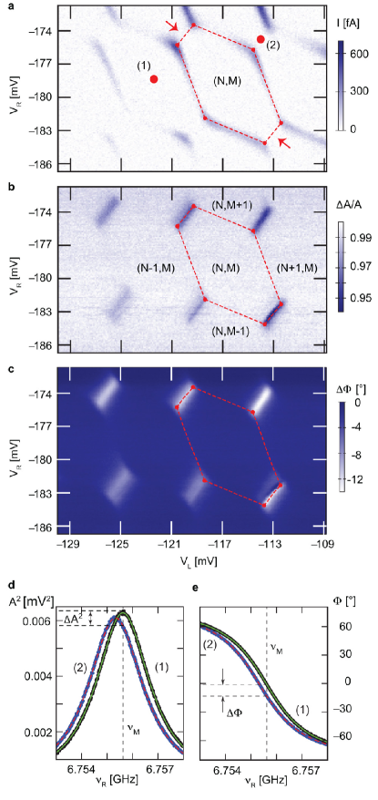
We first investigated the DC transport properties of the double quantum dot (see Fig. 2a) with a source-drain voltage of applied. To change the electrostatic potentials on the quantum dots, the voltages and are varied while all the other gate voltages are fixed. A hexagon charge stability pattern is observed, typical for electron transport through double quantum dots vanderWiel2003 . Within each hexagon, the number of electrons (N, M) in the dots is fixed. At the triple points, where three charge states are degenerate, charge transport is possible and a conductance resonance is observed. The current seen along four of the hexagon boundaries is caused by co-tunneling or molecular orbital states Gustavsson2008 . Along the two remaining hexagon boundaries (indicated with arrows in Fig. 2a) where no DC current was measured, two quantum dot charge states with the same total number of electrons are degenerate vanderWiel2003 . The charging energies of both quantum dots, extracted from Coulomb diamond measurements, are . Both quantum dots contain on the order of 100 electrons and an electron temperature of is estimated from Coulomb resonance linewidths kouwenhoven1997 .
The microwave resonator is designed as in Ref. Frey2011 and we measure a fundamental frequency and loaded quality factor Goeppl2008 , with all gates grounded such that no quantum dots are formed. The resonator is well isolated from thermal radiation originating from the higher temperature stages of the dilution refrigerator, and is hence approximately in its thermal ground state with average thermal photon number .
When the double quantum dot is formed by applying appropriate gate voltages, we find that the resonator frequency and linewidth are sensitively dependent on the double dot gate voltage configuration. In Fig. 2d and e, the amplitude and phase transmission spectrum of the microwave resonator is shown, for the two voltage settings indicated with (1) and (2) in Fig. 2a. Note that here, and in all further microwave transmission measurements, source and drain are grounded. In both configurations (1) and (2), transport is blocked between the leads due to Coulomb blockade. However, in (1), the electron number in both dots is fixed, whereas in (2), a pair of left and right dot charge states are degenerate and hybridized states are formed. Different resonance frequencies and maximum transmission amplitudes are seen in the two cases. This indicates that there is a strong interaction between the double dot and the resonator.
We now proceed to measure the double dot using the resonator, working with a fixed probe frequency and recording the transmitted amplitude and phase. Such measurements for the same gate voltage ranges as in Fig. 2a are shown in Fig. 2b and c, and the same hexagon pattern shown in Fig. 2a is also overlayed (red dashed line). Amplitude and phase changes are observed at the triple points and along the interdot charge transfer lines where left and right dot charge states are degenerate. There is however no clear change of the microwave signal measured along the cotunneling lines. The hexagon pattern shown in Fig. 2b and c could be observed over a range of more than 10 electrons in both left and right dot, including gate voltage settings where the tunneling rates were so small that the DC current through the double quantum dot could not be detected in direct transport measurements (). These measurements suggest that the microwave signal is sensitive to electron exchange between the two dots rather than with the leads.
We now examine the transmitted phase at in the vicinity of one particular interdot charge transfer line, for different values of interdot tunnel coupling energy , tuned using . More negative gives a smaller . The two plunger gates are swept (rather than ), to minimize the change of the tunnel rates to the leads. In Fig. 3a and b the center gate is set to and respectively. are set such that the tunneling rates to the leads are too small to measure DC transport. Despite the small change in between the two measurements, a clear difference is observed. In Fig. 3a, two regions of negative phase shift are seen either side of a region of positive phase shift along the interdot charge transfer line. In Fig. 3b however, a single region of negative phase shift is seen, similar to the features shown in Fig. 2c. Note that negative/positive phase shifts translate directly to negative/positive resonance frequency shifts (see Fig. 2d and e).
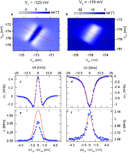
In order to directly determine the resonator frequency shift and linewidth across the interdot charge transfer line, and are swept in parallel following the red dashed lines in Fig. 3a and b. For each voltage setting the full transmission spectrum (see Fig. 2d) is recorded, which allows pure frequency shifts to be easily distinguished from dissipative effects. The parameters and are obtained by fitting these spectra to Lorentzians, and are plotted with respect to the plunger gate voltage changes for the two different interdot tunnel coupling strengths in Fig. 3 c-f.
In order to explain the observations seen in Fig. 3, the hybrid system is modeled as a charge qubit Hayashi2003 coupled to a quantized harmonic oscillator, with the Jaynes-Cummings Hamiltonian in the rotating wave approximation Childress2004 ,
| (1) | |||
Here is the resonator frequency, the detuning energy between the charge qubit states, the tunnel coupling energy between the dots, and the coupling energy between the resonator and the qubit. The photon number operator is , and and are Pauli operators for the qubit.
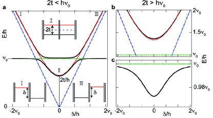
The two lowest eigenenergies of the coupled system are displayed as a function of in Fig. 4a, and Fig. 4b and c, for the cases and respectively. The bare resonator frequency and bare charge qubit transition frequency are modified in the presence of a finite coupling to give the solid black lines in Fig. 4a. Within this model, which does not include decoherence, an avoided level crossing occurs at Blais2004 . In Fig. 4b and c, the dispersive case is displayed in which is far detuned from , for all . The presence of the qubit (Fig. 4b) now only results in a shift of the resonator frequency to values below (Fig. 4c) Blais2004 .
We now compare the data shown in Fig. 3c-f to steady-state numerical simulations of the Hamiltonian (equation (1)), including cavity and qubit damping, and qubit decoherence, in a Markovian master equation formulation WallsMilburnBook . The results are shown as red lines in Fig. 3c-f. We take a relaxation rate typical for charge qubits Fujisawa1998 , and the bare resonator frequency and linewidth from measurements. A factor is used to convert gate voltage settings to detuning energy , shown on the top axis of Fig. 3c-f. We find that the simulations lie close to the data if we include a coupling strength for all datasets, but take a different tunneling energy and dephasing rate for the two different settings of . For (Fig. 3d and f), we use , and , corresponding to the dispersive case (Fig. 4c), to obtain close agreement with the phase shift and linewidth data. For (Fig. 3c and e), we use , and a significantly larger . In this case, the charge qubit crosses the resonator in the model, but anticrossings are not observed due to the large dephasing . Moreover, while the phase shift is in close agreement, the measured linewidth (Fig. 4e) is lower than in the simulation. There are many possible causes for this discrepancy. Indeed, this simple model does not take into account the -dependence of the double quantum dot relaxation Fujisawa1998 and dephasing Hayashi2003 ; Petersson2010a rates. Moreover, our Markovian approach assumes white rather than 1/f noise. This can be expected to lead to discrepancies, especially given the large value of the dephasing rate used here.
The result of this comparison to simulation indicates that the qubit dephasing is by far the dominant decoherence mechanism, and it was checked that inclusion of finite temperature or a higher value of could not explain the data. It was also confirmed both experimentally and in simulation that the results in Fig. 3 are independent of coherent resonator population up to . The displayed measurements used to obtain good signal-to-noise while keeping the measurement time short to avoid rare charge reconfigurations.
We have successfully demonstrated the dipole coupling of a double quantum dot to an on-chip superconducting microwave resonator, and probed the double dot charge stability diagram by measuring resonator frequency shifts. Two different characteristic regimes with interdot tunnel couplings of the double quantum dot above or below the resonator frequency could be observed and explained. Our architecture offers a new way to probe semiconductor quantum systems in the microwave regime, and may be used, for example, for high energy-resolution measurements of double quantum dots Jin2011 , and fast time-resolved measurements, in addition to being a promising platform for scalable hybrid solid-state quantum information processing. The presented scheme could be extended to other material systems, manipulating and reading out spin qubits Hanson2007 and coupling them to a microwave resonator using either ferromagnetic leads Cottet2010 or spin orbit effects Trif2008 .
While preparing this manuscript we became aware of a related work Delbecq2011 , in which a carbon nanotube single quantum dot and its fermionic leads were coupled to a microwave resonator.
References
- (1) Nakamura, Y., Pashkin, Yu. A. & Tsai, J.S. Coherent control of macroscopic quantum states in a single-Cooper-pair box. Nature 395, 786-788 (1999).
- (2) Hayashi, T., Fujisawa, T., Cheong, H.D., Jeong, Y.H. & Hirayama, Y. Coherent Manipulation of Electronic States in a Double Quantum Dot. Phys. Rev. Lett. 91, 226804 (2003).
- (3) Nature insight: Quantum coherence. Nature 453, 1003 1049 (2008).
- (4) Wallraff, A. et al. Strong coupling of a single photon to a superconducting qubit using circuit quantum electrodynamics. Nature 431, 162-167 (2004).
- (5) Schoelkopf, R.J. & Girvin, S.M. Wiring up quantum systems. Nature 451, 664-669 (2008).
- (6) Majer, J. et al. Coupling Superconducting Qubits via a Cavity Bus. Nature 449, 443-447 (2007).
- (7) Kouwenhoven, L.P. et al. Electron transport in quantum dots. Kluwer Series E 345, 105-214 (1997).
- (8) van der Wiel, W.G. et al. Electron transport through double quantum dots, Rev. Mod. Phys. 75, 1 (2003).
- (9) Hanson, R., Kouwenhoven, L.P., Petta, J.R., Tarucha, S. & Vandersypen, L.M.K. Spins in few-electron quantum dots. Rev. Mod. Phys. 79, 4 (2007).
- (10) Lu, W., Zhongqing, J., Pfeiffer, L., West, K.W. & Rimberg, A.J. Real-time detection of electron tunnelling in a quantum dot. Nature 423, 422-425 (2003).
- (11) Reilly, D.J., Marcus, C.M., Hanson, M.P & Gossard, A.C. Fast single-charge sensing with a rf quantum point contact. Appl. Phys. Lett. 91, 162101 (2007).
- (12) Cassidy, M.C. et al. Single shot charge detection using a radio-frequency quantum point contact. Appl. Phys. Lett. 91, 222104 (2007).
- (13) Müller, T. et al. An in-situ tunable radio-frequency quantum point contact. Appl. Phys. Lett. 97, 202104 (2010).
- (14) Petersson, K.D. et al. Charge and Spin State Readout of a Double Quantum Dot Coupled to a Resonator Nano Letters 10, 2789 (2010).
- (15) Childress, L., Sørensen, A.S. & Lukin, M.D. Mesoscopic cavity quantum electrodynamics with qunatum dots. Phys. Rev. A 69, 042302 (2004).
- (16) Taylor, J.M. et al. Fault-tolerant architecture for quantum computing using electrically controlled semiconductor spins. Nature Phys. 1, 177-183 (2005).
- (17) Burkard, G. & Imamoglu, A. Ultra-long-distance interaction between spin qubits. Phys. Rev. B 74, 041307(R) (2006).
- (18) Taylor, J.M. & Lukin M.D. Cavity quantum electrodynamics with semiconductor double-dot molecules on a chip. arXiv:cond-mat/0605144.
- (19) Gustavsson, S., Studer, M., Leturq, R., Ihn, T. & Ensslin, K. Detecting single-electron tunneling involving virtual processes in real time. Phys. Rev. B. 78, 155309 (2008).
- (20) Frey, T. et al. Characterization of a microwave frequency resonator via a nearby quantum dot. Appl. Phys. Lett. 98, 262105 (2011).
- (21) Göppl, M. et al. Coplanar Waveguide Resonators for Circuit Quantum Electrodynamics. J. Appl. Phys. 104, 113904 (2008).
- (22) Blais, A. et al. Cavity quantum electrodynamics for superconducting electrical circuits: an architecture for quantum computation. Phys. Rev. A 69, 062320 (2004).
- (23) Walls, D. F. & Milburn, G. J. Quantum Optics (Spinger, 2008).
- (24) Fujisawa, T. et al. Spontaneous Emission Spectrum in Double Quantum Dot Devices. Science 282, 932 (1998).
- (25) Petersson, K.D., Petta, J.R., Lu, H. & Gossard, A.C. Quantum coherence in One-Electron Semiconductor Charge Qubit. Phys. Rev. Lett. 105, 246804 (2010).
- (26) Jin, P.Q, Marthaler, M., Cole, J.H., Shnirman,A. & Schön, G. Lasing and transport in a quantum dot-resonator circuit. arXiv:cond-mat/1103.5051.
- (27) Cottet, A. & Kontos, T. Spin Quantum Bit with Ferromagnetic Contacts for Circuit QED. Phys. Rev. Lett. 105, 160502, (2010).
- (28) Trif, M., Golovach, V. N. & Loss D. Spin dynamics in InAs nanowire quantum dots coupled to a transmission line. Phys. Rev. B 77, 045434 (2008).
- (29) Delbecq, M.R. et al. Coupling a quantum dot, fermionic leads and a microwave cavity on-chip. arXiv:1108.4371.
Acknowledgements
We thank C. Rössler, T. Müller and D. Loss for valuable discussions, C. Lang for measurement software, P. Studerus for excellent technical support, and T. Schoch and V. Tshitoyan for their contributions to mesa-edge dot development and numerical simulations respectively.
This work was supported financially by EU IP SOLID, by the Swiss National Science Foundation through the National Center of Competence in Research ‘Quantum Science and Technology’ and by ETH Zurich. A. B. was supported by NSERC, the Alfred P. Sloan Foundation, and CIFAR.
Author contributions
T.F. and P.J.L. fabricated the sample, and set up and carried out the experiments. P.J.L. and A.B. carried out the simulations. M.B. carried out the molecular-beam-epitaxial growth of the GaAs heterostructure. T.F., P.J.L. and K.E. wrote the manuscript in discussion with all authors. T.I., K.E. and A.W. supervised and managed the project.