Dark-bright gap solitons in coupled-mode one-dimensional
saturable waveguide arrays
Abstract
In the present work, we consider the dynamics of dark solitons as one mode of a defocusing photorefractive lattice coupled with bright solitons as a second mode of the lattice. Our investigation is motivated by an experiment which illustrates that such coupled states can exist with both components in the first gap of the linear band spectrum. This finding is further extended by the examination of different possibilities from a theoretical perspective, such as symbiotic ones where the bright component is supported by states of the dark component in the first or second gap, or non-symbiotic ones where the bright soliton is also a first-gap state coupled to a first or second gap state of the dark component. While the obtained states are generally unstable, these instabilities typically bear fairly small growth rates which enable their observation for experimentally relevant propagation distances.
pacs:
05.45.Yv, 42.65.Tg, 42.65.Jx, 42.65.Hw, 42.82.Et, 63.20.PwI Introduction
The examination of the Hamiltonian continuum model with periodic potentials and its discrete analog of lattice dynamical systems has been a topic of increasing popularity over the past few years reviews . This is mainly due to their wide applicability in diverse physical contexts including, but not limited to, the spatial dynamics of optical beams in coupled waveguide arrays reviews1 , optically-induced photonic lattices in nonlinear optics reviews1a , temporal evolution of Bose-Einstein condensates (BECs) in optical lattices in soft-condensed matter physics reviews2 , and the DNA double strand in biophysics reviews3 .
A principal research theme in this direction is the study of existence and stability of coherent structures in these models and their feasibility in experiments. Several years ago, fabrication of nonlinear optical AlGaAs waveguide arrays 7 provided a first prototype where many initial investigations arose, such as discrete diffraction, Peierls barriers, diffraction management 7a , and gap solitons 7b . So far numerous fundamental investigations have been pursued in waveguide arrays including modulational instability MI_dnc , four-wave-mixing effects arising from the coupling of multiple components 2c_dnc , as well as the study of interactions of solitary waves with surfaces dnc_surf . Subsequently, the formation of optically-induced photonic lattices in photorefractive crystals became an ideal platform for the observation of various types of solitonic structures. The theoretical proposal solit and rapid experimental realization of such (mainly 2D) lattices moti ; moti2 , enabled the observation of, among others, dipole dip , necklace neck , and rotary rings solitons as well as discrete vortex1 ; vortex2 and gap motihigher vortices. Recently, waveguide arrays in lithium niobate (LiNbO3) crystal, which possess a self-defocusing nonlinearity, have found significant applications in the study of modulation instability MIchristian , beam interactions shand1 , dark discrete solitons shand2 , bright gap solitons brightSoliton1 , dark solitons in higher gaps darksoliton1 , as well as Rabi oscillations Rabi .
Our goal in this work is to consider the case of vector solitons. Although they have been studied both in the focusing case of bright-vector solitons in strontium barium niobate zcv1 and the defocusing case of bright-gap-vector solitons in LiNbO3 dkv1 , much less work has been done in multi-component settings. Instead of mixtures of two solitary waves of the same type as in the above cases, we aim to examine the mixture of a bright with a dark soliton in photorefractive defocusing waveguide arrays. Such dark-bright states were first created in the absence of lattices in photorefractive crystals over a decade ago seg1 and their interactions were partially monitored seg2 . In the context of BECs such solitary waves were also predicted theoretically BA , and generalizations thereof were considered as well (such as e.g. the dark-dark-bright or bright-bright-dark spinor variants of DDB ). However, it was only quite recently that such structures were experimentally observed hamburg ; engels1 ; engels2 ; engels3 . This has led to a renewed interest in this theme, by addressing the interactions of dark-bright solitons from an integrable theory rajendran or numerical berloff perspective, as well as their higher-dimensional generalizations VB . To the best of our knowledge, there is no earlier investigation of such states in models with a periodic potential except in the context of nonlinear dynamical lattices aj1 .
Our motivation, presented in section II stems from an experiment in defocusing LiNbO3 waveguide arrays where a dark soliton state in the first gap (we will refer to this type of state as “bubble” in what follows) is coupled to a bright soliton in the same gap. We will show that these two waveforms coexist as a solitonic entity. Also, we will present conditions under which such a molecule may break up in its constituents. This, in turn, motivates a more detailed theoretical study of the different types of dark-bright states that can exist in the system. Such coupled states will be identified between either a bubble (in the first gap) or a higher-gap (i.e., the second gap in this case) dark soliton in the one component with either a regular bright soliton or with a bright gap soliton. When a bubble or dark soliton couples to a regular bright one, we refer to these solitons as symbiotic because the bright component can not exist without the supporting dark component (due to the defocusing nature of the nonlinearity). For the coupling with a bright-gap soliton, because both components can persist individually, we refer to these states as non-symbiotic. In section III, we set up the model problem and benchmark it against experimental data by identifying its linear band spectrum. In section IV, the numerical results for the above soliton families will be given. Finally, in section V we summarize our findings and present conclusions as well as some relevant directions for future study.
II Experimental Motivation
To experimentally investigate such molecular solitonic states of dark and bright solitons, we used a 1D waveguide array (WA) fabricated on an iron-doped lithium niobate (LiNbO3) substrate by in-diffusion of titanium at high temperature. Arising from the bulk photovoltaic effect, the substrate crystal displays a saturable type of defocusing nonlinearity WA1 . The transverse direction is parallel to the ferroelectric -axis. The direction of light propagation is along the -axis. The array investigated in the following experiments consists of 250 channels and has a grating period m, which is the summation of the channel width of 5 m and a spacing of 3.5 m between adjacent channels. One of the end facets of the waveguide array sample is polished to optical quality to allow for direct observation of the out-coupled light from the array with the help of a CCD camera.
In our experimental setup, we employed the prism-coupler scheme, with which we can selectively excite different Bloch modes in any desired band. Furthermore, with this method we can determine accurately the band structure of the waveguide array bandstructure1 . The experimental layout is sketched in Fig. 1. First, the input light with a wavelength of 532 nm from a frequency-doubled Nd:YVO4 laser is expanded by a beam expander into a plane wave and then split into two separate beams. One beam propagates through a phase mask covering half of the beam along the transverse direction . As a consequence, the covered half of the input beam experiences an additional phase shift, thus a dark notch is generated at the center of the intensity profile. Another beam is modulated by an oscillating mirror driven by a function generator. With applied external modulation, this beam is mutually incoherent with respect to the other beam. With the combination of two cylindrical lenses L1 and L2, the beam passing the phase mask is then imaged onto the waveguide. Here the focal lengths of the two lenses are chosen in order to generate an ideal width of the dark notch covering about two channels, which is the input light pattern for the excitation of a dark soliton. The other beam is focused meanwhile by lens L2 with a diameter of roughly 10 m and serves as the excitation light for the bright soliton. Both beams are coupled into the waveguide array and co-propagate until they reach the end-facet of the sample. With a high resolution CCD camera, in combination with a 20x microscopic objective lens, we can monitor around 25 channels of the intensity distribution on the end-facet. With this setup, it is possible to adjust the input light distribution for both, the bright soliton and the dark soliton separately, for example, the relative locations of the two solitons on the waveguide array as well as different excitation angles for modes originating from different bands.

In the experiment, a bright gap soliton was excited from the first and a dark soliton from the second band (a “bubble” according to our notation above), both at the edge of the Brillouin zone. The centers of both solitons were carefully adjusted to overlap on the same waveguide channel. We first checked under low optical power (less than 2 nW per channel) the linear diffraction behavior of both the dark component [Fig. 2(a), top row] and bright component [Fig. 2(a), bottom row]. Then, by blocking one of the input beams, we formed individual gap solitons (either dark or bright) by increasing the optical power to appropriately high values [Fig. 2(b)]. In all nonlinear experiments, the dark soliton from the second band was formed under 150 nW optical power per channel. In order to analyze the existence interval of the bubble-bright composite solitons, the input light power of the bright soliton was varied, resulting in different power ratios of dark and bright components. At first, a bright soliton was formed at 200 nW per channel, yielding a power ratio to the bright and dark solitons of 4:3. In this case, we observe a robust co-existence of the two components at the output facet, as shown in Fig. 2(c).

However, when we excite the bright soliton at much higher
power (400 nW per channel, resulting in a power ratio of 8:3), the
propagation constant b of the bright component in this scenario is
further decreased below the existence threshold (see also the theoretical
analysis below), while the propagation constant d of the
dark component’s bubble
state remains essentially unaffected. The result of the experiment in this
situation is a clear spatial shift of the bubble center by one waveguide
channel [Fig. 3(a)] due to the coupling with the bright soliton.
This shift may be understood as the initial phase of a repulsive
interaction of the two constituents, and thus suggests the non-existence
(or strong instability) of bubble-bright solitons for these input
conditions. After reaching the steady-state for the input power ratio
8:3, we blocked the input beam used for excitation of the bright soliton.
Because the nonlinearity in lithium niobate is non-instantaneous, the
negative defect formed by the bright beam is still present and is only slowly
erased due to the photoconductivity generated by the remaining dark beam. As
a consequence, in the d-b plane (see the left panel in Fig. 6) we now move upwards
(i.e., b increases) on a vertical line, reaching back
the existence regime of robust bubble solitary waves.
We thus observe a reversible effect, presented in Fig. 3(b):
namely, after the bright soliton is blocked, the dark soliton is restored to
its original location. This restoration proves directly the repulsive
influence from the dominant bright soliton. When the bright component is switched on again in Fig. 3(c),
once again the strong repulsion between bright and dark components forces
the dark soliton to be shifted by one channel.

III Model setup
In what follows, we will consider composite solitons with a dark (or bubble) wave in one component coupled with a bright mode in the second component in the context of TE-TE modes for the geometry of our waveguide array. We start by presenting the underlying model in the full dimensional form with the paraxial approximation, and then we discuss the non-dimensional variant of the model which will be used for our numerical computations.
III.1 Dynamical equations
The paraxial equations for coupled TE-TE modes of the two beams represented by and in what follows, are given by:
| (1) |
with being the refractive index profile and the propagation direction denoted as the -direction. One can find “stationary” solutions of this system by defining:
| (2) |
where are the propagation constants in the -direction and and the amplitude profiles of each TE mode, which, in turn, satisfy:
| (3) |
The values used in the experiments are the following ones:
| (4) |
(cf. also the discussion given in section II) where is the refractive index of the LiNbO3 substrate for extraordinary polarized light, is the wavelength of the input light, is the period of the waveguide array and is the maximum refractive index change induced by the nonlinearity.
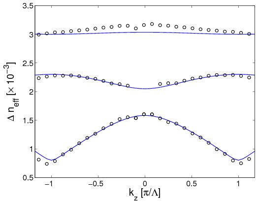
The refractive index profile can be determined by adjusting the experimental Bloch bands showing the change of the effective refractive index , with and being the transverse wavevector in vacuum. The refractive index is then given by:
| (5) |
with
| (6) |
and
| (7) |
Figure 4 shows the correspondence between the experimentally observed Bloch bands bandstructure1 and the theoretically computed ones. Clearly, the above set of parameters offers a very good handle on the linear part of the problem.
III.2 Non-dimensional equations and parameters
The non-dimensional version of the system of Eqs. (III.1) is given by
| (8) |
while the stationary states are solutions of:
| (9) |
The non-dimensional parameters are related to the experimental ones by the following relations:
| (10) |
| (11) |
The parameter has been introduced so that the non-dimensional values are of . Throughout the calculations, it has been fixed to . The sign of indicates either self-focusing (positive) or self-defocusing (negative). Additionally, the nondimensional distances are given by
| (12) |
The refractive index profile and parameters are given now by
| (13) |
| (14) |
and the change of the effective refractive index is
| (15) |
for each (dark and bright) component.
III.3 Stability equations
Once stationary solutions of the boundary value problem (with periodic / anti-periodic boundary conditions, depending on the nature of the examined solution) of Eqs. (III.2) are identified, their linear stability is considered by means of a Bogolyubov-de Gennes analysis. Namely, small perturbations [of order , with ] are introduced in the form
| (16) |
and the ensuing linearized equation are then solved to O, leading to the following eigenvalue problem:
| (17) |
for the eigenfrequency and the associated eigenvector , where are the following operators:
| (18) |
where it has been taken into account that . Once the stationary solutions are found to be linearly unstable (i.e., ), then the dynamical manifestation of the corresponding instabilities is monitored through direct numerical simulations of Eq. (III.2). As we will see in the next section, all of the analyzed solutions are unstable, although their growth rates are so small that long propagation distances are needed in order to observe the emergence of the pertinent instabilities.
IV Numerical results
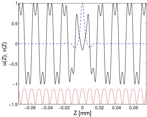
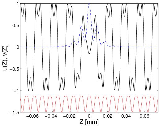
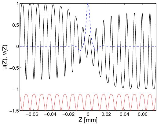
We now present our results for the several types of coherent structures considered in our system in the self-defocusing setting (i.e. ). All of them are composed of a bright soliton in the 1st band gap. The dark structure can be of two types. It may be a bubble, located in the 1st band gap and arising from the top of the second Bloch band in which case the overall phase shift between the two endpoints of the domain is . Alternatively, it may be a (genuine) dark soliton, which emerges from the bottom of the second Bloch band, and, consequently, its propagation constant is found in the second band gap and it bears a phase shift of between the domain endpoints.
We make one more terminological distinction between the different types of waveforms that can arise. In particular, the emerging bubble/dark-bright structures can either be symbiotic or not. In the first case, the bright soliton is unstaggered and emerges from the top of the first band (zero mode). These modes are called symbiotic because an isolated bright component would not exist in this form for the relevant values of the propagation constant; it necessitates the formation of an effective potential by its dark (or bubble) counterpart in order to co-exist with it. In the second (non-symbiotic) case, the bright soliton is staggered and emerges from the bottom of the first band as a genuine gap soliton that would be sustained in the system even in the absence of the other component.
These two distinctions (dark or bubble waves for the first component, symbiotic or non-symbiotic ones depending on the nature of the second component) give rise to four possibilities for the ensuing structures dubbed as follows: symbiotic / non-symbiotic bubble-bright soliton (SBBS / NSBBS) and symbiotic / non-symbiotic dark-bright soliton (SDBS / NSDBS). Among the four, it is the NSBBS that was observed in our experimental motivation in section II. Figure 5 shows prototype examples of the input field profiles for each of these four solutions.
 |
 |
 |
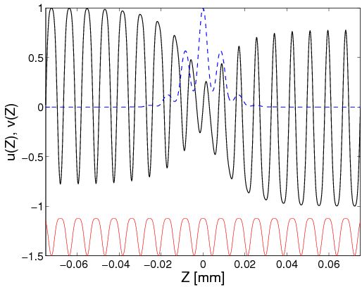 |
As mentioned above, Fig. 4 shows the position of the Bloch bands which are also relevant for the identification of the nonlinear localized modes that arise in the system. In particular, the first band is located in the interval [], the second one is [] and the third one at [].
Our numerical computations show that, in absence of coupling between the modes, the bright soliton can be identified in the first gap for (i.e. , and here as well as below denotes an appropriate shift) whereas bubble-type solutions also exist for (i.e. ) and, in turn, the dark soliton can be identified for lower values of the propagation constant, namely for (i.e. ). In the case of the two coupled beam components within the waveguide array, the existence interval is narrower. Furthermore, the existence range depends qualitatively on the symbiotic / non-symbiotic character of the soliton. More specifically, the accessible range of , for a given , is always wider for symbiotic solitons than for non-symbiotic ones. Additionally, the existence range of symbiotic solitons is limited from above by . Figure 6 depicts the existence range for dark-bright and bubble-bright symbiotic as well as non-symbiotic solitary waves.
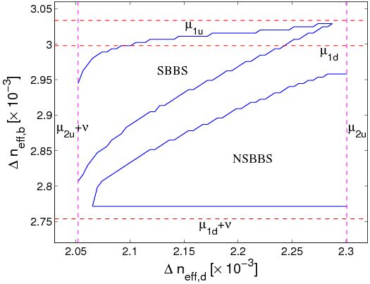 |
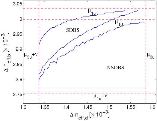 |
 |
 |
 |
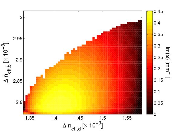 |
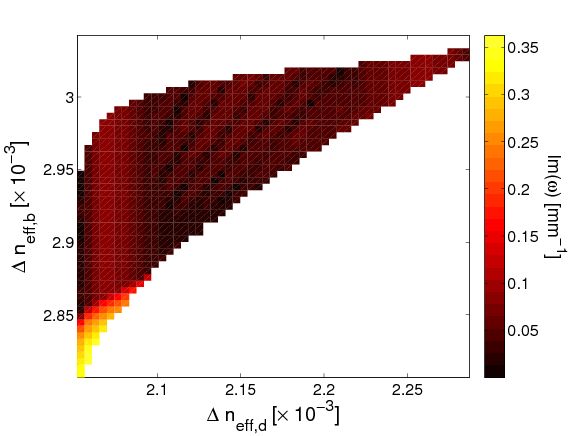
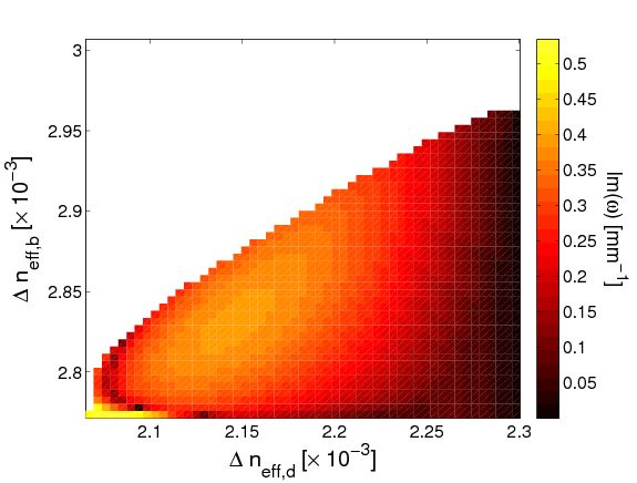
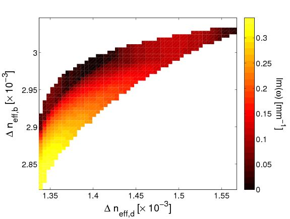
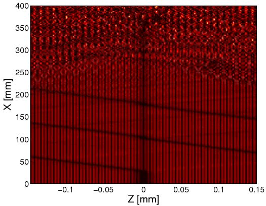
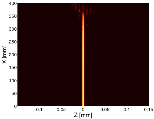
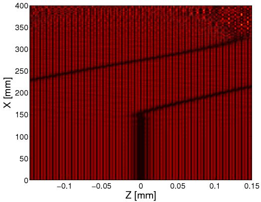
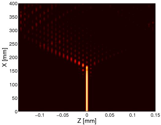
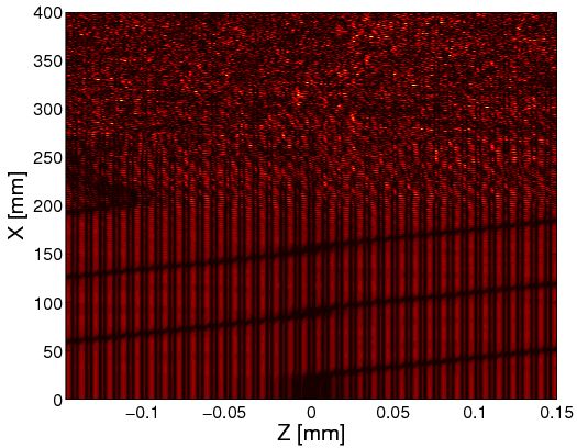
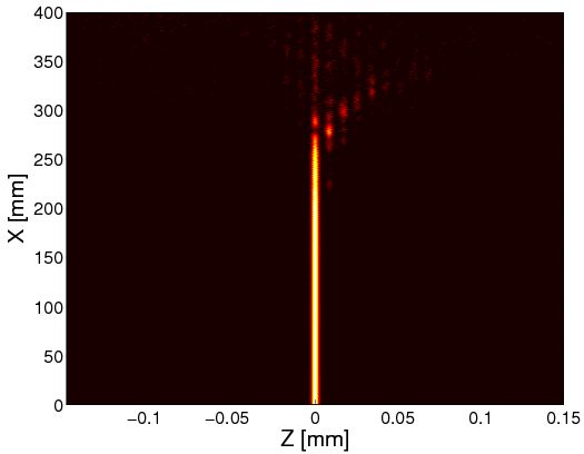
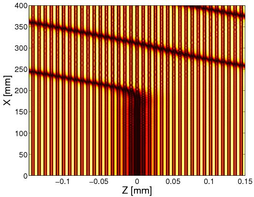
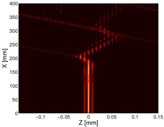
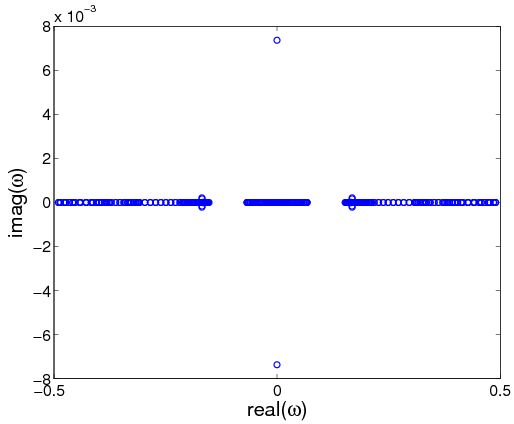
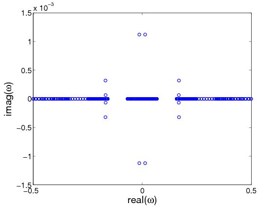
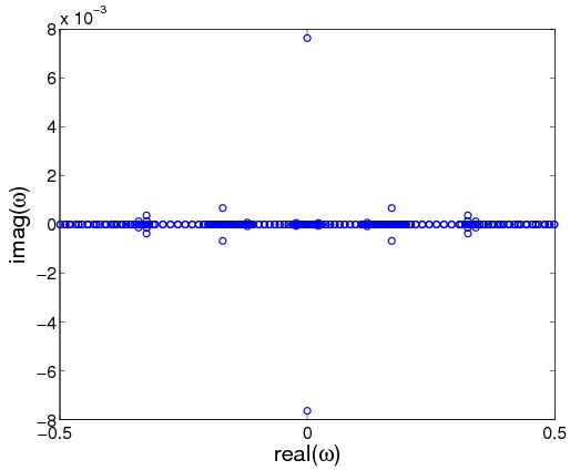
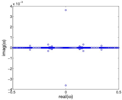
We have examined the linear stability of the obtained solutions, finding that the relevant waveforms are generically unstable in the spectral sense. I.e., we have identified an imaginary or complex eigenfrequency associated with the linearization spectrum around these profiles, however the growth rate is typically fairly small ( in non-dimensional units, i.e., mm-1 in dimensional units) and always less than in non-dimensional units corresponding to 0.5 mm-1 in dimensional ones. Consequently, instabilities appear at a sufficiently large propagation distance (inversely proportional to the above growth rate). Figure 7 shows the growth rate dependence with and for the four analyzed structures; notice the colorbar on the right indicating the magnitude of the respective growth rates. In order to test the effect of instabilities, a random perturbation of magnitude is introduced to the input field profile. The main dynamical observed outcome is the mobility of the dark component of the soliton. This implies a break-up of the structure; however, there are two realizations thereof depending on the symbiotic or non-symbiotic nature of the state. In the case of a non-symbiotic solitons (i.e., for NSBBS and for NSDBS), the bright component remains at rest forming a genuine bright gap soliton. On the other hand, in the symbiotic solitons, this is impossible due to the non-existence of a bright waveform of this type. Hence, most of the bright component energy moves towards the opposite direction of the dark component in the case of the bubble (i.e., for SBBS) while part of the energy moves with the dark component. For the SDBS, most of the energy appears to move together with the dark component. A summary of this scenario is shown in the panels of Fig. 8. To indicate the growth rates and unstable eigenmodes of the solutions dynamically followed in Fig. 8, we show in Fig. 9 their respective spectral planes. It is worth remarking that, in most cases, the instabilities are of exponential and oscillatory type, except in the case of SBBS, where most of the instabilities are purely oscillatory. On the other hand, to connect these results with the experimental motivation of Section II, let us point out that for the NSBBS considered therein the increase of the power is tantamount to a larger instability growth rate and hence the observation of the mobility of the dark component, while the bright one forms a genuine gap soliton in agreement with our numerics (top panel of Fig. 8). This repulsive effect between the two components is also evident through the blocking of the bright channel and the restoration of the bubble at the center, while the reintroduction of the interaction between the beams naturally and reversibly reinstates the repulsive bubble mobility effect.
 |
 |
 |
 |
 |
 |
 |
 |
 |
 |
 |
 |
V Conclusions and Future Challenges
In the work presented in this paper, we have considered the case of two-component dark-bright type solitary wave states in defocusing photorefractive waveguide arrays. Motivated by experiments in LiNbO3 arrays, which illustrated a bubble-type soliton state in one component coupled to a bright gap solitary wave in the second one, we delved into a theoretical examination of the different composite states that can emerge in this system. In particular, we revealed the potential for four distinct types of waves, namely non-symbiotic and symbiotic, dark-bright and bubble-bright ones. We numerically revealed (within a model benchmarked against the linear band structure) the persistence boundaries of such solutions. We also analyzed their linear stablity which exhibits a typically weak instability in all of them (with fairly small growth rates). This instability is so weak that it permits, apparently, the experimental observability of the states. Nevertheless, in suitable regimes even the experimental dynamics manifests the potential break-up of the composite states.
Naturally, this investigation paves the way for numerous additional studies. On the one hand, from an experimental viewpoint it would certainly be interesting to identify the other proposed structures. On the other hand, investigating interactions of such composite structures would also offer relevant insights as was done experimentally e.g. with simpler states in shand1 , or as was done numerically in aj1 and in different (BEC) dark-bright contexts in engels3 ; berloff . Generalizations of such states in two-dimensional waveguide arrays with the formation of vortex-bright states VB or of genuinely discrete variants thereof interlaced would also be an exciting theme for future investigations.
Acknowledgements.
DK thanks the German Research Foundation (DFG, grant KI482/11-2) for financial support of this research. PGK gratefully acknowledges support from the US-NSF through grants DMS-0806762 and CMMI-1000337 and from the Alexander von Humboldt Foundation as well as the Alexander S. Onassis Public Benefit Foundation. JC acknowledges financial support from the MICINN project FIS2008-04848.References
- (1) S. Aubry, Physica D 103, 201, (1997); S. Flach and C.R. Willis, Phys. Rep. 295, 181 (1998); D. Hennig and G. Tsironis, Phys. Rep. 307, 333 (1999); P.G. Kevrekidis, K.O. Rasmussen, and A.R. Bishop, Int. J. Mod. Phys. B 15, 2833 (2001); A. Gorbach and S. Flach, Phys. Rep. 467, 1 (2008).
- (2) D.N. Christodoulides, F. Lederer and Y. Silberberg, Nature 424, 817 (2003); Yu.S. Kivshar and G.P. Agrawal, Optical Solitons: From Fibers to Photonic Crystals, Academic Press (San Diego, 2003).
- (3) F. Lederer, G.I. Stegeman, D.N. Christodoulides, G. Assanto, M. Segev, and Y. Silberberg, Phys. Rep. 463, 1 (2008).
- (4) P.G. Kevrekidis and D.J. Frantzeskakis, Mod. Phys. Lett. B 18, 173 (2004); V.V. Konotop and V.A. Brazhnyi, Mod. Phys. Lett. B 18, 627, (2004); P.G. Kevrekidis, R. Carretero-González, D.J. Frantzeskakis, and I.G. Kevrekidis, Mod. Phys. Lett. B 18, 1481 (2004).
- (5) M. Peyrard, Nonlinearity 17, R1 (2004).
- (6) H.S. Eisenberg, Y. Silberberg, R. Morandotti, A.R. Boyd, and J.S. Aitchison, Phys. Rev. Lett. 81, 3383 (1998).
- (7) R. Morandotti, U. Peschel, J.S. Aitchison, H.S. Eisenberg, and Y. Silberberg, Phys. Rev. Lett. 83, 2726 (1999).
- (8) D. Mandelik, R. Morandotti, J.S. Aitchison, and Y. Silberberg, Phys. Rev. Lett. 92, 093904 (2004).
- (9) J. Meier, G.I. Stegeman, D.N. Christodoulides, Y. Silberberg, R. Morandotti, H. Yang, G. Salamo, M. Sorel, and J.S. Aitchison, Phys. Rev. Lett. 92, 163902 (2004).
- (10) J. Meier, J. Hudock, D.N. Christodoulides, G. Stegeman, Y. Silberberg, R. Morandotti, and J.S. Aitchison, Phys. Rev. Lett. 91, 143907 (2003).
- (11) S. Suntsov, K.G. Makris, D.N. Christodoulides, G.I. Stegeman, A. Haché, R. Morandotti, H. Yang, G. Salamo, and M. Sorel, Phys. Rev. Lett. 96, 063901 (2006).
- (12) N.K. Efremidis, S. Sears, D.N. Christodoulides, J.W. Fleischer, and M. Segev, Phys. Rev. E 66, 046602 (2002).
- (13) J.W. Fleischer, M. Segev, N.K. Efremidis, and D.N. Christodoulides, Nature 422, 147-150 (2003).
- (14) H. Martin, E.D. Eugenieva, Z. Chen, and D.N. Christodoulides, Phys. Rev. Lett. 92, 123902 (2004); J.W. Fleischer, T. Carmon, M. Segev, N.K. Efremidis, and D.N. Christodoulides, Phys. Rev. Lett. 90, 023902 (2003).
- (15) J. Yang, I. Makasyuk, A. Bezryadina, and Z. Chen, Opt. Lett. 29, 1662-1664 (2004).
- (16) J. Yang, I. Makasyuk, P.G. Kevrekidis, H. Martin, B.A. Malomed, D.J. Frantzeskakis, and Z. Chen, Phys. Rev. Lett. 94, 113902 (2005).
- (17) Y.V. Kartashov, V.A. Vysloukh, and L. Torner, Phys. Rev. Lett. 93, 093904 (2004); X. Wang, Z. Chen, and P.G. Kevrekidis, Phys. Rev. Lett. 96, 083904 (2006).
- (18) D.N. Neshev, T.J. Alexander, E.A. Ostrovskaya, Yu.S. Kivshar, H. Martin, I. Makasyuk, and Z. Chen, Phys. Rev. Lett. 92, 123903 (2004).
- (19) J.W. Fleischer, G. Bartal, O. Cohen, O. Manela, M. Segev, J. Hudock, and D.N. Christodoulides, Phys. Rev. Lett. 92, 123904 (2004).
- (20) G. Bartal, O. Manela, O. Cohen, J.W. Fleischer, and M. Segev, Phys. Rev. Lett. 95, 053904 (2005).
- (21) C.E. Rüter, J. Wisniewski, M. Stepić, and D. Kip, Opt. Express 15, 6320 (2007).
- (22) M. Stepić, E. Smirnov, C.E. Rüter, L. Prönekke, and D. Kip, Phys. Rev. 74, 046614 (2006).
- (23) E. Smirnov, C.E. Rüter, M. Stepić, D. Kip, and V. Shandarov, Phys. Rev. E 74, 065601 (2006).
- (24) D. Kip, C.E. Rüter, R. Dong, Z. Wang, and J. Xu, Opt. Lett. 33, 2056-2058 (2008).
- (25) R. Dong, C.E. Rüter, D. Song, J. Xu, and D. Kip, Opt. Express 18, 27493-27498 (2010).
- (26) K. Shandarova, C.E. Rüter, D. Kip, K.G. Makris, D.N. Christodoulides, O. Peleg, and M. Segev, Phys. Rev. Lett. 102, 123905 (2009).
- (27) Z. Chen, A. Bezryadina, I. Makasyuk, and J. Yang, Opt. Lett. 29, 1656 (2004).
- (28) R. Vicencio, E. Smirnov, C.E. Rüter, D. Kip, and M. Stepić, Phys. Rev. A 76, 033816 (2007).
- (29) Z. Chen, M. Segev, T.H. Coskun, D.N. Christodoulides, Yu.S. Kivshar, and V.V. Afanasjev, Opt. Lett. 21, 1821 (1996).
- (30) E.A. Ostrovskaya, Yu.S. Kivshar, Z. Chen, and M. Segev, Opt. Lett. 24, 327 (1999).
- (31) Th. Busch and J.R. Anglin, Phys. Rev. Lett. 87, 010401 (2001).
- (32) H.E. Nistazakis, D.J. Frantzeskakis, P.G. Kevrekidis, B.A. Malomed, and R. Carretero-González, Phys. Rev. A 77, 033612 (2008).
- (33) C. Becker, S. Stellmer, P. Soltan-Panahi, S. Dörscher, M. Baumert, E.-M. Richter, J. Kronjäger, K. Bongs, and K. Sengstock, Nature Phys. 4, 496 (2008).
- (34) C. Hamner, J.J. Chang, P. Engels, and M.A. Hoefer, Phys. Rev. Lett. 106, 065302 (2011).
- (35) M.A. Hoefer, C. Hamner, J.J. Chang, and P. Engels, arXiv:1007.4947.
- (36) S. Middelkamp, J.J. Chang, C. Hamner, R. Carretero-González, P.G. Kevrekidis, V. Achilleos, D.J. Frantzeskakis, P. Schmelcher, and P. Engels, Phys. Lett. A 375, 642 (2011).
- (37) S. Rajendran, P. Muruganandam, and M. Lakshmanan, J. Phys. B 42, 145307 (2009).
- (38) C. Yin, N.G. Berloff, V.M. Pérez-García, V.A. Brazhnyi, and H. Michinel, arXiv:1003.4617.
- (39) K.J.H. Law, P.G. Kevrekidis and L.S. Tuckerman, Phys. Rev. Lett. 105, 160405 (2010).
- (40) A. Álvarez, J. Cuevas, F.R. Romero, and P.G. Kevrekidis, Physica D 240, 767 (2011).
- (41) D. Kip, Appl. Phys. B 67, 131-150 (1998).
- (42) C.E. Rüter, J. Wisniewski, and D. Kip, Opt. Lett. 31, 2768-2770 (2006).
- (43) J. Cuevas, Q.E. Hoq, H. Susanto, and P.G. Kevrekidis, Physica D 238, 2216 (2009).