Mixed finite elements for numerical weather prediction
Abstract
We show how two-dimensional mixed finite element methods that satisfy the conditions of finite element exterior calculus can be used for the horizontal discretisation of dynamical cores for numerical weather prediction on pseudo-uniform grids. This family of mixed finite element methods can be thought of in the numerical weather prediction context as a generalisation of the popular polygonal C-grid finite difference methods. There are a few major advantages: the mixed finite element methods do not require an orthogonal grid, and they allow a degree of flexibility that can be exploited to ensure an appropriate ratio between the velocity and pressure degrees of freedom so as to avoid spurious mode branches in the numerical dispersion relation. These methods preserve several properties of the C-grid method when applied to linear barotropic wave propagation, namely: a) energy conservation, b) mass conservation, c) no spurious pressure modes, and d) steady geostrophic modes on the -plane. We explain how these properties are preserved, and describe two examples that can be used on pseudo-uniform grids: the recently-developed modified RT0-Q0 element pair on quadrilaterals and the BDFM1- element pair on triangles. All of these mixed finite element methods have an exact 2:1 ratio of velocity degrees of freedom to pressure degrees of freedom. Finally we illustrate the properties with some numerical examples.
keywords:
Mixed finite elements , stability , steady geostrophic states , geophysical fluid dynamics , numerical weather predictionMSC:
[2010] 65M601 Introduction
There are a number of groups that have been developing dynamical cores for numerical weather prediction (NWP) and climate modelling, based on triangular meshes on the sphere or on the dual meshes composed of hexagons together with twelve pentagons (Ringler et al., 2000; Majewski et al., 2002; Satoh et al., 2008). These grids are referred to as pseudo-uniform grids since they have edge lengths that satisfy , as , where is the average edge length, for some positive constants , . The principal reason for adopting these grids is that they provide a direct addressing data structure whilst avoiding the polar singularity of the latitude-longitude grid, which introduces a bottleneck to scaling on massively parallel architectures due to the convergence of meridians. One approach to developing numerical discretisations on triangular or hexagonal grids is to adapt the staggered Arakawa C-grid finite difference method on quadrilaterals (Arakawa and Lamb, 1977) (used in several currently operational NWP models, such as the UK Met Office Unified Model (Davies et al., 2005)) since this type of staggering prevents pressure modes (non-constant functions on the pressure grid that have zero numerical gradient). By defining discrete curl and divergence operators which satisfy div curl, it is possible to construct C-grid discretisations for horizontal wave propagation which have stationary geostrophic modes on the -plane (Thuburn et al., 2009), a necessary condition for accurate representation of geostrophic adjustment processes. These operators can be used to construct energy and enstrophy C-grid discretisations for the nonlinear rotating shallow-water equations using the vector invariant form (Ringler et al., 2010). The drawback with using the C-grid finite difference method on triangles or hexagons instead of quadrilaterals is that the ratio of velocity and pressure degrees of freedom (DOF) is altered. The quadrilateral C-grid has one pressure DOF stored at the centre of each grid cell, and two velocity DOF per grid cell (normal velocity is stored at each of the four edges, which are each shared with the neighbouring cell on the other side of the face)111Here, and in the rest of the paper, we consider compact domains without boundary such as the sphere and rectangles with double periodic boundary conditions.. This is considered the ideal ratio, since the velocity then has an equal number of rotational and divergent DOF which are coupled together in the correct way so that there are two inertia-gravity modes (the inward and outward propagating modes) for each Rossby mode. On the other hand, the triangular C-grid has only velocity DOF per grid cell, and the hexagonal C-grid has velocity DOF per grid cell. This means that the triangular C-grid has four inertia-gravity modes per Rossby mode; the extra spurious inertia-gravity branch has a frequency range that decreases with Rossby deformation radius, leading to “checkerboard patterns” in the divergence when the deformation radius is small (as it can be in the ocean, or when there are many vertical layers). The hexagonal C-grid has an equal number of inertia-gravity and Rossby modes; the extra spurious Rossby mode has very low frequencies and propagates Eastwards on the -plane (Thuburn, 2008). The effects of these spurious Rossby modes has not been reported in practice but there are concerns amongst the operational NWP community that if spurious modes are supported by the grid, then they might be initialised during the data assimilation process or by physics parameterisations (Staniforth, personal communication). It may also be the case that the spurious modes lead to spurious spread/lack of spread in ensemble forecasts. Careful numerical experiments are required to investigate this concern.
The finite element method provides the opportunity to alter the number of degrees of freedom per triangular element to ameliorate this problem. A number of finite element pairs on triangles have been proposed for geophysical fluid dynamics, mostly in the ocean modelling community (Walters and Casulli, 1998; Le Roux et al., 1998, 2005; Cotter et al., 2009; Comblen et al., 2010; Le Roux et al., 2007). In (Rostand and Le Roux, 2008), the lowest order Brezzi-Douglas-Marini element pair (Brezzi et al., 1985), known as BDM1, was investigated in the context of the discrete shallow-water equations. The velocity space is piecewise linear with continuous normal components, and the pressure space is piecewise constant. The natural data structure for the velocity space stores two normal velocity components on each edge, and hence there are 3 velocity DOF per triangular element and 1 pressure DOF. There are too many velocity DOF and hence there will be too many Rossby modes per inertia-gravity mode, just as for the hexagonal C-grid.
The key result of this paper is in showing that discretisations of the linear rotating shallow water equations on the -plane constructed using these spaces on arbitrary meshes satisfy a crucial property, namely that geostrophic modes are exactly steady. This is achieved by making use of the discrete Helmholtz decomposition, within the framework of discrete exterior calculus (Arnold et al., 2006). As described in (Arnold, 2002), existence of such a decomposition requires that the following diagram commutes:
| (1) |
where , and are suitably chosen projection operators. The same Helmholtz decomposition can then be used to study the discrete dispersion relations for the numerical discretisation. Within this framework, we then conclude that an optimal choice is to have which, at least in the periodic plane, satisfies necessary conditions for absence of both spurious inertia-gravity and spurious Rossby waves.
The rest of this paper is organised as follows. The general framework of mixed finite element methods applied to the linear rotating shallow-water equations is described in Section 2, and the four properties of energy conservation, local mass conservation, absence of spurious pressure modes and steady geostrophic modes are discussed. In Section 3, two examples are then introduced that fit into this framework, and numerical results are presented in section 4. Finally, we give a summary and outlook in Section 5.
2 Mixed finite elements for geophysical fluid dynamics
In this section we describe how mixed finite elements can be used to build flexible discretisations on pseudo-uniform grids. We concentrate on the rotating shallow-water equations which are regarded in the numerical weather prediction community as being a simplified model that contains many of the issues arising in the horizontal discretisation for dynamical cores. Since in this paper we are concerned with wave propagation properties, we restrict attention to the linearised equations on the -plane, -plane or the sphere. First, we introduce the mixed finite element formulation applied to the linear rotating shallow-water equations, then we discuss various properties of the formulation that are a requirement for numerical weather prediction applications, namely global energy and local mass conservation, absence of spurious pressure modes and steady geostrophic states. These properties all rely on exact sequence properties, i.e. div-curl relations, as described in (Arnold et al., 2006).
2.1 Spatial discretisation of the linear rotating shallow-water equations
In this paper we consider the discretisation of the linear rotating shallow-water equations on a two dimensional surface that is embedded in three dimensions (which we restrict to be compact with no boundaries, e.g. the sphere or double periodic plane):
| (2) |
where is the horizontal velocity, , is the Coriolis parameter, , is the gravitational acceleration, is the mean layer thickness, is the layer thickness, is the normal to the surface , and and are appropriate invariant gradient and divergence operators defined on the surface. We form the finite element approximation by multiplying by time-independent test functions and , integrating over the domain, integrating the pressure gradient term by parts in the momentum equation, and finally restricting the velocity trial and test functions and to a finite element subspace (where is the space of square integrable velocity fields whose divergence is also square integrable), and the elevation trial and test functions and to the finite element subspace (where is the space of square integrable functions):
| (3) | |||||
| (4) |
After discretisation in time, these equations are solved in practise by introducing basis expansions for , , , and and solving the resulting matrix-vector systems for the basis coefficients.
In this framework we restrict the choice of finite element spaces and so that
The divergence should map from S onto V, so that for all functions there exists a velocity field with . Such spaces are known as “div-conforming”. Furthermore we require that there exists a “streamfunction” space such that
where the operator (the curl, which we shall write as ) maps onto the kernel of in S. A consequence of these properties is that functions in are continuous, vector fields in only have continuous normal components and functions in are discontinuous.
2.2 Energy conservation
Global energy conservation for the linearised equations is a requirement of numerical weather prediction models for various reasons, in particular because it helps to prevent numerical sources of unbalanced fast waves. It is also a precursor to a energy-conserving discretisation of the nonlinear equations using the vector-invariant formulation. For the mixed finite element method, global energy conservation is an immediate consequence of the Galerkin finite element formulation. The conserved energy of equations (2) is
Substituting the solutions and to equations (3-4) and taking the time derivative gives
Choosing and in equations (3-4) then gives
2.3 Local mass conservation
Local mass conservation is a requirement for numerical weather prediction models since it prevents spurious sources and sinks of mass. For the nonlinear density equation, this can be achieved using a finite volume or discontinuous Galerkin method. For mixed finite element methods of the type used in this paper applied to the linear equations, consistency and discontinuity of functions in requires that element indicator functions (i.e. functions that are equal to 1 in one element and 0 in the others) are contained in . Selecting the element indicator function for element as the test function in equation (4) gives
where is the boundary of element . Since has continuous normal components on element boundaries, this means that the flux of is continuous and hence is locally conserved.
2.4 Absence of spurious pressure modes and stability of discrete Poisson equation
The principle reason for using the staggered C-grid for numerical weather prediction is that the collocated A-grid, in which pressure and both components of velocity are stored at the same grid locations, suffers from a checkerboard pressure mode which has vanishing numerical gradient when the centred difference approximation is used, despite being oscillatory in space. This pressure mode rapidly pollutes the numerical solution in the presence of nonlinearity, boundary conditions and forcing, and can be easily excited by physics subgrid parameterisations or initialisation via data assimilation from noisy data.
In the context of mixed finite element methods applied to the equation set (2), spurious pressure modes relate to the discretised gradient of a function defined by
On uniform grids, spurious pressure modes are functions from the pressure space which have zero discretised gradient even though is non-zero. On unstructured grids or grids with varying edge lengths, spurious pressure modes are functions which have discretised gradient becoming arbitrarily small as the maximum edge length tends to zero, despite their actual gradient staying bounded away from zero. Such functions would prevent the numerical solution of equations (2) converging at the optimal rate predicted by approximation theory. We make the following definition of a spurious pressure mode.
Definition 1 (Spurious pressure modes).
A mixed finite element space is said to be free of spurious pressure modes if there exists independent of such that for all , there exists nonzero satisfying
| (5) |
Condition (5) is one of two sufficient conditions for numerical stability of the mixed finite element discretisation of the Poisson equation given by
This discretisation is stable (i.e. small changes in the right-hand side lead to small changes in the solution field in the limit as tends to zero) if Condition (5) holds, together with the condition that there exists independent of such that
| (6) |
for all such that for all . As reviewed in Arnold (2002), Condition (5) is satisfied if it is possible to define a bounded projection such that the following diagram commutes:
| (7) |
where is the usual projection operator. This means that taking any square integrable velocity field with square integrable divergence, evaluating the divergence and projecting into produces the same result as projecting into using and evaluating the divergence. The projection is constructed by applying an projection of normal components on element edges, ensuring that is -orthogonal to gradients of functions from in each element, and ensuring the remaining degrees of freedom in are -orthogonal to divergence-free functions in each element. We shall explain how this is done for the two examples described in Section 3. To check that the diagram (7) commutes, it is sufficient to show that
for each element , since this defines the projection into the discontinuous space . This is easily checked using integration by parts:
as required.
As also reviewed in Arnold (2002), Condition (6) is satisfied if vector fields with divergence orthogonal to are in fact divergence-free. This is satisfied by the types of mixed finite element methods considered in this paper since the divergence maps from S into V, and so the projection of into is simply the inclusion. Hence, if the divergence is orthogonal to , the divergence must be zero, and so (6) is satisfied.
2.5 Discrete Helmholtz decomposition
Proof of the condition that geostrophic modes are steady requires the construction of a discrete Helmholtz decomposition. Since Condition (5) holds, the discrete gradient operator , has no non-trivial kernel. For any , the curl of satisfies
for any , and hence the curl from to and the discrete divergence from to map onto orthogonal subspaces of . This means that there is a one-to-one mapping between elements of and , defining a discrete Helmholtz decomposition
| (8) |
where is the space of discrete harmonic velocity fields
The dimension of is the same as the dimension of the space of harmonic velocity fields
i.e., velocity fields with vanishing divergence and (weak) curl (In the periodic plane, these harmonic velocity fields are the constant velocity fields, but there are no harmonic velocity fields on the sphere); however in the general case (Arnold et al., 2006). The kernel of in is the subspace of constant functions, and stability results (as described in Section 2.4) imply that the kernel of in is the subspace of constant functions, and hence we can use Equation (8) to obtain a DOF count for .
and hence
For our DOF requirement , we obtain
which becomes for the periodic plane and for the sphere. If , then and vice versa. This will become important when we examine wave propagation in Section 2.8.
2.6 Vorticity and divergence
The discrete vorticity associated with the velocity is defined as such that
| (9) |
It is possible to obtain from the discrete vorticity and the divergence by solving two elliptic problems for the streamfunction and velocity potential . To obtain the streamfunction , we use the Helmholtz decomposition and rewrite equation (9) as
which is the usual finite element discretisation of the Poisson equation for . To obtain the vector potential requires the solution of the coupled system
This is the mixed finite element approximation to the Poisson equation already discussed in Section 2.4; if the Conditions (5) and (6) are satisfied, the coupled system is well-posed.
2.7 Steady geostrophic modes
On the -plane (planar domain with constant ), geostrophic balanced states satisfying are steady since . The remaining solutions of the linear rotating shallow-water equations are fast inertia-gravity waves. In the quasi-geostrophic limit (slow, large scale motion), when nonlinear terms and spatially varying are introduced, these steady states become slowly-evolving balanced states that characterise large-scale weather systems. It is crucial that a discretisation gives rise to steady geostrophic states on the -plane, otherwise when nonlinear terms and spherical geometry are introduced, balanced states will emit noisy inertia-gravity waves that will pollute the numerical solution over timescales that are much shorter than that required for a weather forecast. To show that mixed finite element methods have steady geostrophic modes, we follow the approach of Thuburn et al. (2009), namely we aim to show that vanishing divergence implies steady vorticity, then checking that vanishing divergence and steady vorticity implies steady velocity.
To obtain a geostrophic balanced state corresponding to a given streamfunction , we initialise and as follows:
-
1.
Set .
-
2.
Set from the geostrophic balance relation
(10)
Substitution in equation (3) then gives
having noted that and so we may choose in equation (10). To show that , first note that and hence . Equation (4) thus becomes
and hence . This means that the geostrophic balanced state is steady.
2.8 Numerical dispersion relations
In this section we consider the numerical wave propagation properties of this family of finite element discretisations, on the -plane and on the -plane in the quasi-geostrophic limit.
Dispersion relations are computed by assuming time-harmonic solutions proportional to (a valid assumption if the equations are invariant under time translations) and studying the resulting eigenvalue problem. For the continuous equations on the periodic plane, the equations are also invariant under spatial translations and so it may be assumed that the eigensolutions take the form where is restricted so that the periodic boundary conditions are satisfied. Substitution in the equations of motion leads to an algebraic system relating to : the dispersion relation. For the linear shallow-water equations this system is most easily obtained by using the Helmholtz decomposition for . Numerical dispersion relations for continuous-time spatial discretisations are also computed by assuming time-harmonic solutions, leading to a discrete eigenvalue problem. If a structured mesh is used on the periodic plane with a set of discrete translation symmetries then eigensolutions satisfy the property that translating from one cell to another by results in the discrete eigensolution changing by a factor of , where is again chosen so that the periodic boundary conditions are satisfied. This can again lead to a numerical relationship between and , obtained for both the -plane, and the -plane in the quasi-geostrophic limit, for the hexagonal C-grid in Thuburn (2008), and for the finite element pair in Cotter and Ham (2011).
Here, we discuss the properties of the discrete eigenvalue problem arising from the finite element spaces from the framework of this paper. The discussion makes use of the discrete Helmholtz decomposition. In the -plane case, substitution of the discrete Helmholtz decomposition into equations (3-4) and assuming time-harmonic solutions yields
| (11) | |||||
| (12) | |||||
| (13) |
for all test functions , . Next we define projections and by
These projections are uniquely defined since uses the standard continuous finite element discretisation of the Laplace operator which is solvable by the Lax-Milgram theorem when is restricted to mean zero functions, and uses the mixed finite element discretisation of the Laplace operator using the spaces and which is solvable by the stability conditions (5) and (6) when is also restricted to mean zero functions.
Using these projections, and the fact that the divergence operator maps from to , equations (11-13) become
| (14) | |||||
| (15) | |||||
| (16) |
and elimination of and use of the definition of gives
| (17) | |||||
where is obtained from equation (16). The first row of equation (17) is the discretisation of the continuous eigenvalue problem for the rotating shallow-water equations using the mixed finite element spaces and . In this case the eigenvalues of this discrete eigenvalue problem converge to the eigenvalues of the continuous problem at the optimal rate as described in Boffi et al. (1997). However, there are two extra terms in the bottom row of equation (17). The second term converges to zero for smooth , and use might be made of spectral perturbation theory to examine what effect this has on the discrete eigenvalue problem; we have not yet developed a technique to do this. However, the impact of the first term in the second row is more immediately clear, since it involves projecting from to and back to again. If has larger dimension than , which is the case for the lowest order Raviart-Thomas element on triangles, for example, then this double projection will have a kernel, and will not be small. This leads to spurious branches of inertia-gravity waves, i.e. branches of solutions of the discrete eigenvalue problem that do not converge to solutions of the continuous eigenvalue problem as . See Danilov (2010) for numerical examples illustrating this spurious modes, in particular Figures 2,3 and 4. Hence, is a necessary condition for the absence of spurious divergent inertia-gravity modes.
A similar approach can be taken to studying the -plane solutions in the quasi-geostrophic limit. Substitution of the discrete Helmholtz decomposition into equations (3-4) and assuming time-harmonic solutions yields
| (18) | |||||
| (19) | |||||
| (20) |
In the usual quasi-geostrophic limit, the leading order solution is
where , and are the leading order terms in the low Rossby number expansion of , and respectively. This is the same as the geostrophic steady state formula for the -plane, and we have
The next order in the expansion of the equations (we do not make use of the next order in the equation) is
| (21) | |||||
| (22) |
Again, the embedding property implies that . Since is continuous and has continuous normal components, we may integrate by parts in the second two terms in equation (21), to obtain
The first line is the continuous finite element approximation to the Rossby wave eigenvalue problem using the finite element space , which has convergent eigenvalues. The second line is a perturbation involving which will not always be small if has a non-trivial kernel. This will be the case if , as occurs in the lowest order Brezzi-Douglas-Marini (BDM1) element on triangles (Brezzi et al., 1985) which has as the streamfunction space, and hence . If has a non-trivial kernel, this will lead to spurious Rossby wave branches of the numerical dispersion relation. We conclude that is a necessary condition for avoiding both spurious divergent modes and spurious irrotational modes. Note that this is not a sufficient condition since it is still possible for or to have non-trivial kernel even in this case. This condition motivates the selection of examples of mixed finite element spaces given in the next section.
3 Examples
In this section we provide two examples of mixed finite element spaces that are suitable for constructing pseudo-uniform grids on the sphere, and that have the additional property that there are exactly twice as many velocity degrees of freedom as pressure degrees of freedom, which prevents the presence of spurious mode branches. The first example is the modified Raviart-Thomas element on quadrilaterals, and the second example is the Brezzi-Douglas-Fortin-Marini element on triangles.
3.1 Modified Raviart-Thomas element on quadrilaterals
There have been several efforts at developing numerical weather prediction models based on a cubed sphere grid (see Putman and Lin (2007), for example) in which a grid on the surface of a cube is projected to a sphere. The drawback in using such is grid is that to obtain a C-grid finite difference method with stationary geostrophic states, the scheme of Thuburn et al. (2009) must be used, which requires the grid to be orthogonal in the sense that lines joining adjacent pressure nodes must cross cell boundaries at right-angles. On the cubed sphere, this condition does not produce a pseudo-uniform grid since elements become clustered near the poles as the resolution is increased. Mixed finite elements provide extra freedom to design numerical schemes since the orthogonality condition is not a requirement; it is replaced by the conditions on finite element spaces specified in Section 2.
The lowest-order Raviart-Thomas finite element space is the mixed finite element analogue of the C-grid since the pressure space is piecewise constant functions, and the velocity fields are constrained to be have constant, continuous normal components on element edge. This means that one normal component of velocity must be stored on each element edge, just like the C-grid. The velocity fields are constructed on a square reference element with coordinates , on which the -component of velocity is obtained by linear interpolation between constant values on the and edges, and the -component is obtained by linear interpolation between constant values on the and edges. In these coordinates, the divergence is constant. In any physical element in the mesh, we define a coordinate mapping , and the velocity in is obtained via the Piola transformation
which preserves flux integrals
guaranteeing continuity of normal fluxes. The divergence satisfies
where is the divergence in the local coordinates . If the coordinate transformation is affine (elements are parallelograms), the determinant of the Jacobian is constant, and so the divergence of the velocity is constant in each element. However, for general quadrilateral elements (required for the cubed sphere), the coordinate transformation is bilinear, with linear determinant of the Jacobian. The solution, proposed by Boffi and Gastaldi (2009), is to modify the basis functions by adding a divergent correction with vanishing normal components on the boundary that makes the divergence constant. The corresponding streamfunction space is the usual continuous bilinear space on quadrilaterals, often denoted , and it can easily be shown that the operator maps from into in this case. In fact, the Boffi-Gastaldi correction adds a purely divergent component to the velocity field and so the embedding property is not affected.
The RT0-Q0 finite element space has one pressure degree of freedom per quadrilateral element, and one velocity degree of freedom per edge. Since (for periodic boundary conditions or the sphere) each edge is shared by two elements, this means that there are exactly twice as many velocity degrees of freedom as pressure degrees of freedom. This modified Raviart-Thomas finite element space satisfies all the conditions that we require in this paper and hence has potential for use on pseudo-uniform grids for numerical weather prediction.
3.2 Brezzi-Douglas-Fortin-Marini element on triangles
There is an analogous Raviart-Thomas finite element space on triangles which satisfies the required embedding properties. However, these spaces satisfy in general. For example, the lowest order finite element space RT0-P0 has one pressure degree of freedom per element, and one velocity degree of freedom per edge, meaning that . The BDM1 element on triangles has one pressure degree of freedom per element and two velocity degrees of freedom per edge, meaning that , so . However, the little-used lowest order Brezzi-Douglas-Fortin-Marini (BDFM1) element together with on triangles satisfies . The BDFM family of elements for quadrilaterals was introduced in Brezzi et al. (1987), and an analogous family for triangles was described in Brezzi and Fortin (1991). On triangles it is infrequently used since the BDM and RT families have less degrees of freedom for the same order of convergence (after suitable post-processing). However, these extra degrees of freedom are useful to us here since they mean that .
Here we describe the BDFM1 element on triangles as an augmentation of the BDM1 element on triangles, which we recall first. Given a triangle , we define to be the space of -th order polynomials on . We define the following spaces on :
| velocity space | ||||
| pressure space |
For a triangulation of the domain , we define the velocity space
where is the space of vector fields with square integrable divergence, which requires that has continuous normal component across triangle edges. The pressure space is
with no continuity requirements across edges.
A convenient set of local nodal basis functions for is defined by choosing two node points on each triangle edge, each node located at one of the vertices belonging to that edge: a total of six node points. For example, in the triangle shown in Figure 1, on edge there are two node points, one at vertex and one at vertex . The basis function associated with edge and vertex is
where is the unit tangent vector to edge and where are the barycentric coordinates associated with vertices , and respectively. It can easily be checked that has normal component equal to 1 at the node point located at vertex on edge , and normal component equal to zero at each of the other node points. The other six basis functions are constructed in a similar manner.


To increase the number of degrees of freedom in each triangle in the triangulation , we define the local BDFM1 space by
Since all of the vectors in vanish on the boundary of , they do not alter the values of the normal components at the boundary, and so there are no additional continuity constraints. The dimension of is 12, and there are 9 independent degrees of freedom which do not vanish on the boundary, which means that .
A convenient set of local nodal basis functions for is defined by locating nodes that store the tangential component of velocity at the centre of each edge. The tangential component of velocity is permitted to be discontinuous and so a different value of the tangential component will be stored on each side of the edge. The basis function associated with the node at the centre of edge is
It can easily be checked that has vanishing normal component on all edges, tangential component equal to 1 at the centre of edge and vanishing tangential component on the other two edges. The other two basis functions are constructed in a similar manner.
The augmented velocity space on the triangulation is defined as
The pressure space is defined as
with no continuity requirements. For this mixed element pair the velocity space has 6 DOF per element, and the pressure space has 3 DOF per element, hence there are twice as many velocity DOF as pressure DOF, just as for the C-grid finite difference method on quadrilaterals.
For our augmented velocity space, it is easy to define the projection operator . The projection is computed element by element and guarantees the continuity of across element edges. The projection on an element is defined from the following conditions:
| (23) | |||||
| (24) | |||||
| (25) |
where is the cubic “bubble” function (as used in the MINI element (Arnold et al., 1984)). In a triangle , the cubic bubble function is the unique cubic polynomial which takes the value 1 at the barycentre and 0 on all three edges. The streamfunction space is
Equation (23) comprises the BDM1 projection operator, fixing six degrees of freedom. The components of the extra degrees of freedom are not affected since they all satisfy on . The vector field lies inside since it is quadratic (being the skew gradient of a cubic function, ) and has vanishing normal component on (since is zero on ). If we construct an orthogonal (relative to the inner product) decomposition of into then we see that equation (25) only involves the component, and equation (24) only involves the remaining two components, as
because vanishes on . The space is spanned by constant vector fields, and hence equation (24) fixes the two degrees of freedom in . Bounds on can be obtained by following the steps of Brezzi et al. (1985), since it simply involves projection onto various moments.
We define the streamfunction space as the usual Lagrange continuous quadratic space augmented by cubic bubble functions. For any function , the curl maps into : . Furthermore, we may define a projection operator by
for each element . To show that the projections commute with , i.e. , we check each of the conditions (23-25). Condition (23) becomes
| (26) | |||||
where are the two vertices at either end of edge , and having noted that is constant for . Condition (24) becomes
where we have used equation (26). Finally, condition (25) becomes
since is constant in and is zero on .
Counting global degrees of freedom,
where is the Euler characteristic of the domain which is equal to 0 for the doubly-periodic domain and equal to 2 on the sphere. On the sphere there are two extra constraints: namely that the divergence and the vorticity both integrate to zero, and so in both cases . Finally, we note that each triangle has three edges which are each shared with one other triangle, and hence .
4 Numerical results
In this section we illustrate the properties of the BDFM1 finite element space applied to the linear rotating shallow-water equations. The equations were integrated numerically using the implicit midpoint rule, and the resulting discrete system was solved by using hybridisation which is a standard technique for solving elliptic problems (see Brezzi and Fortin (1991) for a detailed description) in which the continuity constraints on the velocity space are dropped, and are instead enforced in the equation by Lagrange multipliers. It becomes possible to eliminate both the velocity and free surface variables from the matrix equation, leaving a symmetric positive definite system to solve for the Lagrange multipliers. The velocity and free surface variables can then be reconstructed element-by-element. One of the benefits of this approach is that it can be applied when the Coriolis term is present, resulting in a fully implicit treatment of this term. In our numerical tests this system was solved using a direct solver. In the case of BDFM1-, there are three Lagrange multipliers per element.
In the test cases with variable Coriolis parameter , a continuous piecewise quadratic representation of was used.
4.1 Steady states for the -plane
We verified that the geostrophic states are exactly steady on the -plane for the BDFM1 finite element space by randomly generating streamfunction fields from the streamfunction space on the same mesh as used for the finite element pair steady state tests in Cotter et al. (2009), with streamfunction equal to zero on the boundary. This mesh is a planar unstructured mesh in the plane in a square region. The velocity was initialised by setting where is the unit normal to the domain i.e. , and was obtained by solving the discrete elliptic system
| (27) | |||||
| (28) |
with . We then integrated the equations forward for arbitrary lengths of time and observed that the layer thickness and velocity remained constant up to machine precision. We also conducted the same experiment on an icosehedral mesh of the unit sphere with (following the “-sphere” experiment of Thuburn et al. (2009)) and obtained the same result.
4.2 Kelvin waves in a circular basin
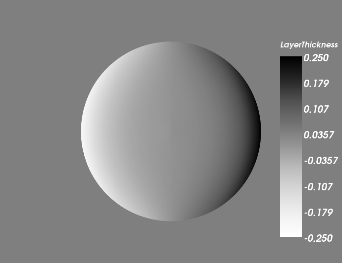
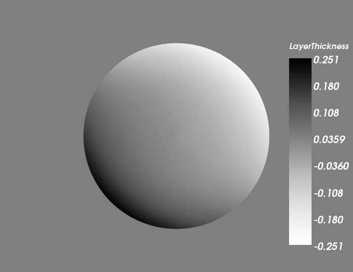
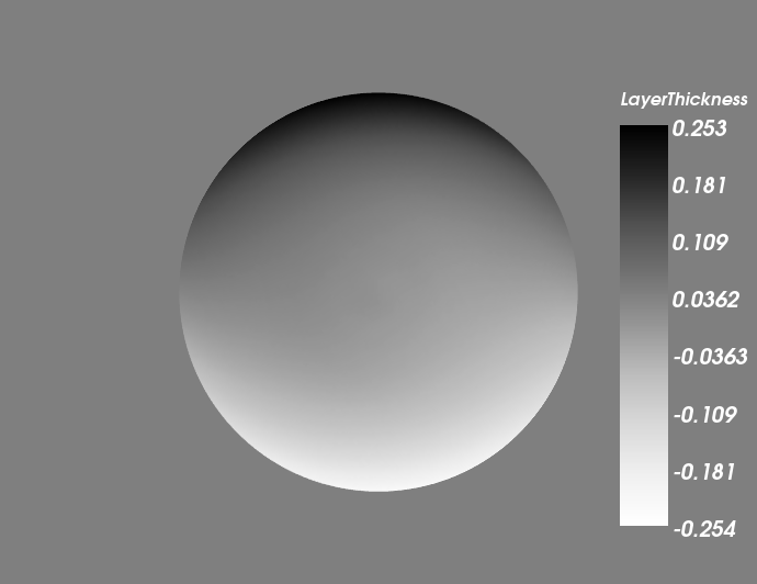
Coastal Kelvin waves provide a challenging test since they propagate at the gravity wave speed along the coast but are geostrophically balanced in the direction normal to the coast. We used the Kelvin wave initial condition for a circular basin with unit dimensionless radius as proposed in Ham et al. (2007), with and . We integrated the equations until 10 dimensionless time units with a time step size .
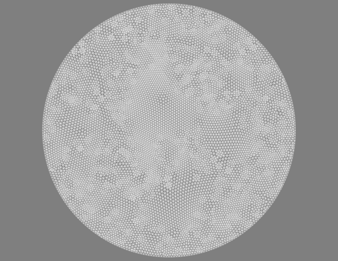
The mesh used for the Kelvin wave calculation is shown in Figure 2. Some snapshots of the numerical solution are shown in Figure 3. There are no spurious gravity waves observed, which means that the BDFM1 discretisation is maintaining geostrophic balance in the normal direction as well as the Kelvin wave structure.
4.3 Rossby waves
To verify the convergence of the method we compared against the Rossby wave solution with streamfunction
in a square domain with nondimensional length 1, with nondimensional wave propagation speed , and non-dimensional Coriolis parameter
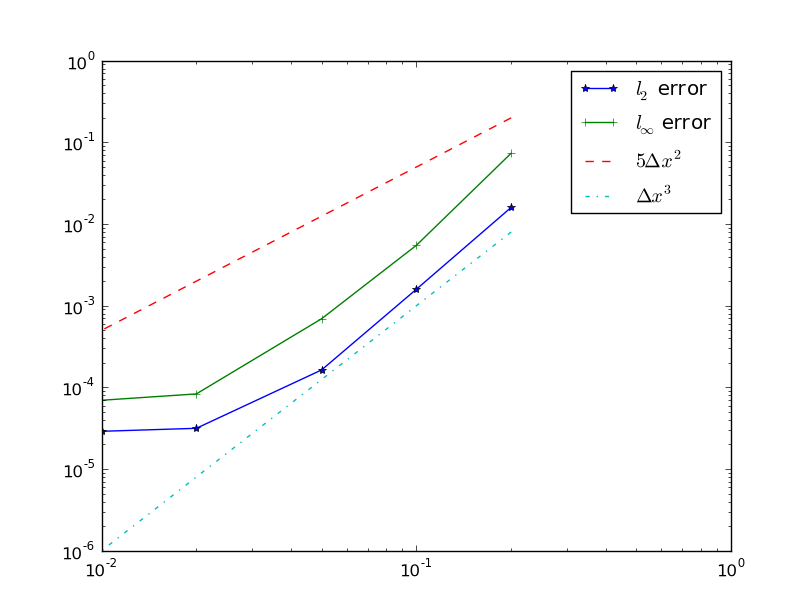
and periodic boundary conditions in the -direction. This is an exact solution of the Rossby wave equation, but is only an asymptotic limit solution of the linearised rotating shallow-water equations as , with error. This means that for sufficiently small grid width and time step size we expect the error to dominate. The numerical solution was initialised from this streamfunction following the balanced initialisation approach described in Section 4.1. A plot of the error is shown in figure 4. We observe convergence until the error saturates because of the finite Rossby number. We attribute this third order convergence to the fact that in Section 2.8 the discrete Rossby wave equation was shown to be equal to usual continuous finite element discretisation of the Rossby wave equation using the space , plus a perturbation. Since contains all of the continuous piecewise quadratic functions, we would expect third-order convergence provided that the perturbation converges to zero sufficiently fast (although we do not currently have any estimates for the convergence of the perturbation).
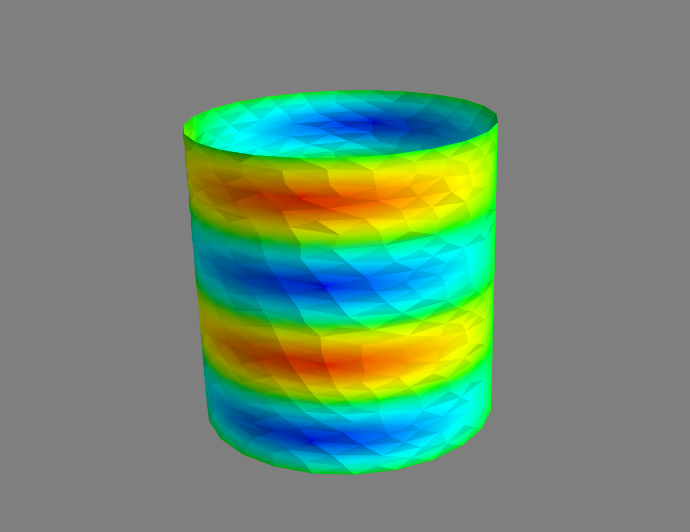
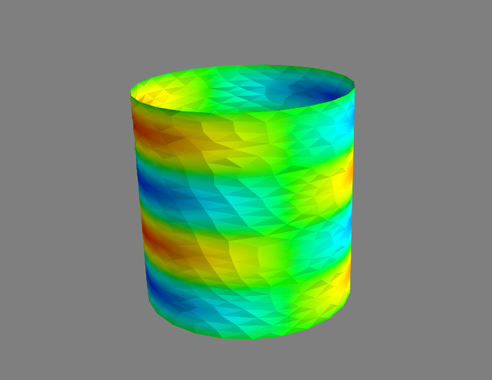
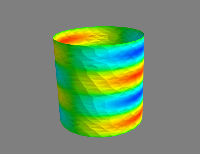
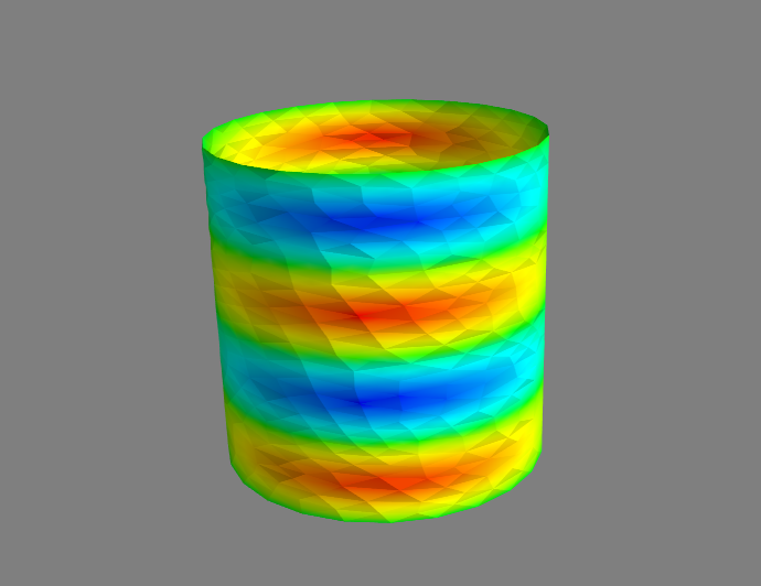
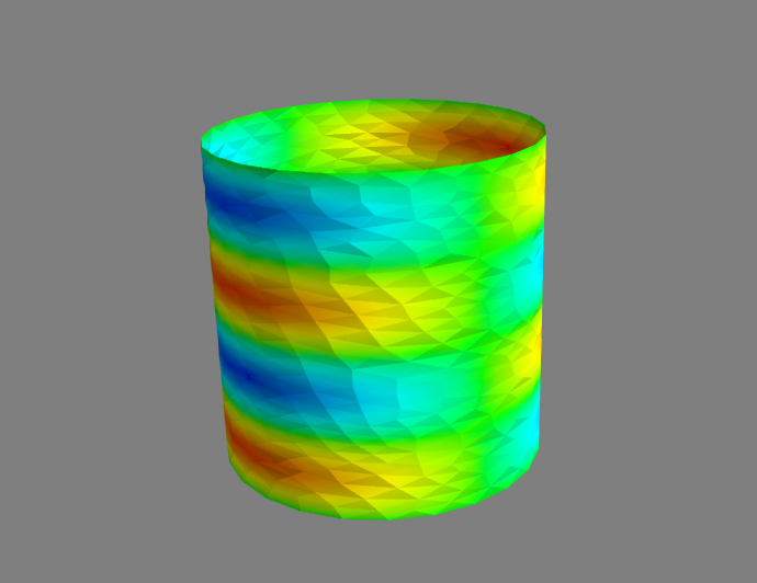
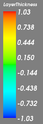
To demonstrate the performance of the numerical scheme on arbitrary manifolds we constructed an unstructured mesh of a cylinder with unit dimensionless radius and dimensionless height equal to 2. The Coriolis parameter was set to and other parameters were kept the same as the planar Rossby wave tests. We call this configuration the “”-tube since it corresponds to a -plane that has been wrapped into a cylinder. Some plots of the numerical integration of this test case are provided in Figure 5; no unbalanced motions are visible from the plots.
4.4 Solid rotation on the sphere
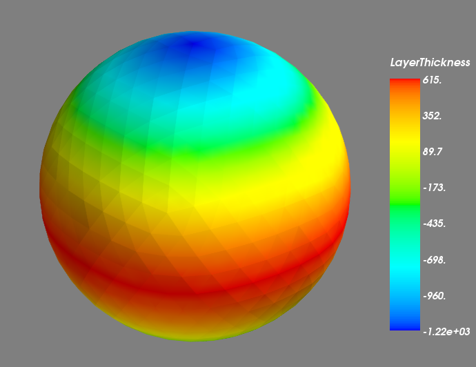
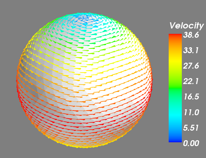
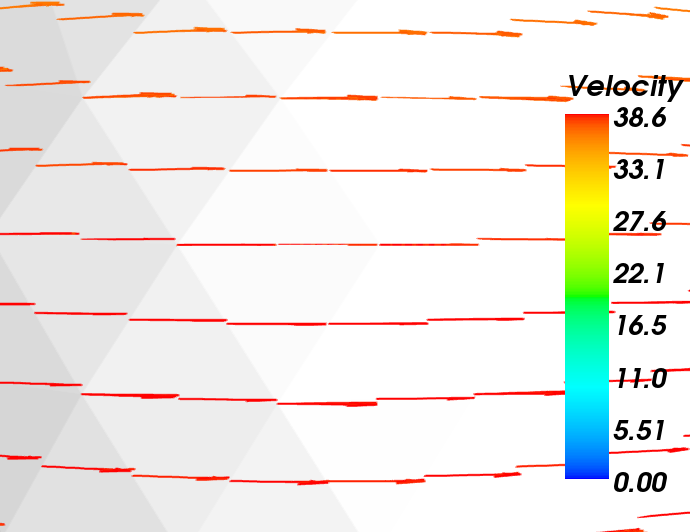
To investigate the grid imprinting caused by the finite element scheme, we integrated the linear rotating shallow-water equations on the sphere with initial condition obtained from the streamfunction , where is the latitude, , and is the radius of the sphere. The rotation rate was , and . This solution is a steady state solution of the linear equations with varying because of the cylindrical symmetry; in general we do not expect numerical discretisations which break this symmetry to preserve the steady state.
In our experiment, we used a level 4 icosahedral mesh (each icosahedron edge being subdivided into 8) of the sphere. The velocity and free surface elevation were initialised according to the procedure described in Section 4.1. To measure the deviation from a steady state, the free surface elevation after 10 days of simulation with a timestep of 3600s was subtracted from the initial condition. Remarkably, the errors were almost indistinguishable from round-off error. It turns out that this is because of the mapping used between functions on the sphere, and functions on the icosahedral mesh with flat triangular elements used for the numerical integration. The finite element streamfunction was initialised according to , where is the mapping given as follows:
This mapping preserves the value of , and rescales and onto the sphere. Hence, we obtain , which can be represented exactly in the streamfunction space . The same mapping is also applied to the finite element representation of the Coriolis parameter , and we obtain which can also be represented exactly. Following the balanced initialisation procedure, the finite element free surface elevation field is obtained by projecting the mapping into the pressure space , where is the continuous balanced free surface elevation. Substitution into the velocity equation gives
| [definition of , and ] | ||||
| [integration by parts] |
where the second step follows since and so we can use the fact that is a finite element projection of in , and where in the last step integration by parts was possible since is continuous and has continuous normal components.
5 Summary and outlook
In this paper we described some properties of applying finite element spaces satisfying the div and curl embedding properties, applied to the rotating linear shallow water equations, in order to illustrate their possible suitability for numerical weather prediction on quasi-uniform grids. In this context, these methods can be thought of as more flexible extensions of the mimetic C-grid finite difference method that is currently used in many dynamical cores. This extra flexibility means that non-orthogonal grids and grids with rapid changes of mesh resolution can be used, and the ratio of pressure and velocity degrees of freedom can be adjusted to avoid spurious mode branches. We showed that spurious inertia-gravity mode branches will exist if and spurious Rossby mode branches will exist if . The discrete Helmholtz decomposition implies that where is the space of harmonic velocity fields on the chosen domain. This motivates the search for finite element spaces with that can be used on pseudo-uniform grids on the sphere. In Section 3 we gave two low-order examples: the modified RT0-Q0 element pair for the non-orthogonal cubed sphere, and the BDFM1- element pair for triangles, the latter of which was illustrated with some numerical examples in Section 4.
In future work, we shall aim to benchmark the augmented mixed element pair in the context of numerical weather prediction and ocean modelling. One of the benefits of this pair is that discontinuous Galerkin methods can be used for the nonlinear continuity equation for the density. These methods are locally conservative, have minimal dispersion and diffusion errors, and can be made TVB in combination with appropriate slope limiters as described in Cockburn and Shu (2001). Furthermore, as described in (White et al., 2008), if one wishes to have tracer transport that is both conservative and consistent, it is necessary use the pressure space for tracers too. This means that tracer transport can (must) also use the discontinuous Galerkin method.
Finally, we note that although the BDFM(k)-PkDG finite element spaces do not have a 2:1 ratio of velocity DOFs to pressure DOFs, there does exists a family of higher-order versions of the BDFM1 element pair with a 2:1 ratio, obtained by appropriately augmenting the spaces (with odd) with higher-order components that vanish on element boundaries. This does not work out so neatly for since it is also necessary to augment the space for pressure, to obtain stable element pairs with twice as many velocity DOF as pressure DOF per triangle. In future work, we shall investigate these higher-order element pairs, as well as extensions to tetrahedra in three-dimensions that can be used in unstructured mesh ocean modelling.
6 Acknowledgements
The authors acknowledge funding from NERC grants NE/I016007/1, NE/I02013X/1, and NE/I000747/1. The shallow water solver was produced using the Imperial College Ocean Model finite element library, unstructured meshes were generated using GMSH, and the icosahedral mesh generator was provided by John Thuburn. Plots were obtained using the Python Matplotlib library and Mayavi2.
References
- Arakawa and Lamb (1977) Arakawa, A., Lamb, V., 1977. Computational design of the basic dynamical processes of the UCLA general circulation model. In: Chang, J. (Ed.), Methods in Computational Physics. Vol. 17. Academic Press, pp. 173–265.
- Arnold (2002) Arnold, D., 2002. Differential complexes and numerical stability. In: Tatsien, L. (Ed.), Proceedings of the ICM, Beijing 2002. Vol. 1. pp. 137–157.
- Arnold et al. (1984) Arnold, D., Brezzi, F., Fortin, M., 1984. A stable finite element for the Stokes equations. CALCOLO 21 (4), 337–344.
- Arnold et al. (2006) Arnold, D., Falk, R., Winther, R., 2006. Finite element exterior calculus, homological techniques, and applications. Acta Numerica 15, 1–155.
- Boffi et al. (1997) Boffi, D., Brezzi, F., Gastaldi, L., 1997. On the convergence of eigenvalues for mixed formulations. Ann. Scuola Norm. Sup. Pisa, Cl. Sci, XXV, 131–154.
- Boffi and Gastaldi (2009) Boffi, D., Gastaldi, L., 2009. Some remarks on quadrilateral mixed finite elements. Computers and Structures 87 (11-12), 751–757.
- Brezzi (1974) Brezzi, F., 1974. On the existence, uniqueness and approximation of saddle point problems arising from Lagrange multipliers. Rev. Française Automat. Informat. Recherche Opérationnel le Sér. Rouge Anal. Numér. 8, 129–151.
- Brezzi et al. (1987) Brezzi, F., Douglas, J., Fortin, M., Marini, L., 1987. Efficient rectangular mixed finite elements in two and three space variables. Modélisation mathématique et analyse numérique 21 (4), 581–604.
- Brezzi and Fortin (1991) Brezzi, F., Fortin, M., 1991. Mixed and hybrid finite element methods. Springer-Verlag.
- Brezzi et al. (1985) Brezzi, F., Jr, J. D., Marini, L., 1985. Two families of mixed finite elements for second order elliptic problems. Numerische Mathematik 47 (2), 217–235.
- Cockburn and Shu (2001) Cockburn, B., Shu, C.-W., 2001. Runge-Kutta discontinuous Galerkin methods for convection-dominated problems. J. Sci. Comp. 16 (3), 173–261.
- Comblen et al. (2010) Comblen, R., Lambrechts, J., Remacle, J.-F., Legat, V., 2010. Practical evaluation of five partly discontinuous finite element pairs for the non-conservative shallow water equations. Int. J. Num. Meth. Fluid. 63 (6), 701–724.
- Cotter and Ham (2011) Cotter, C., Ham, D., 2011. Numerical wave propagation for the triangular p1dg-p2 finite element pair. Journal of Computational Physics 230 (8), 2806 – 2820.
- Cotter et al. (2009) Cotter, C. J., Ham, D. A., Pain, C. C., 2009. A mixed discontinuous/continuous finite element pair for shallow-water ocean modelling. Ocean Modelling 26, 86–90.
- Danilov (2010) Danilov, S., 2010. On utility of triangular C-grid type discretization for numerical modeling of large-scale ocean flows. Ocean Dynamics 60 (6), 1361–1369.
- Davies et al. (2005) Davies, T., Cullen, M. J. P., Malcolm, A. J., Mawson, M. H., Staniforth, A., White, A. A., Wood, N., 2005. A new dynamical core for the Met Office’s global and regional modelling of the atmosphere. Q. J. Roy. Met. Soc 131 (608), 1759–1782.
- Ham et al. (2007) Ham, D. A., Kramer, S. C., Stelling, G. S., Pietrzak, J., 2007. The symmetry and stability of unstructured mesh c-grid shallow water models under the influence of coriolis. Ocean Modelling 16 (1-2), 47 – 60.
- Le Roux et al. (2007) Le Roux, D., Rostand, V., Pouliot, B., 2007. Analysis of numerically induced oscillations in 2d finite-element shallow-water models part I: Inertia-gravity waves. SIAM J. Sci. Comput. 29 (1), 331–360.
- Le Roux et al. (2005) Le Roux, D., Sène, A., Rostand, V., Hanert, E., 2005. On some spurious mode issues in shallow-water models using a linear algebra approach. Ocean Modelling, 83–94.
- Le Roux et al. (1998) Le Roux, D., Staniforth, A., Lin, C. A., 1998. Finite elements for shallow-water equation ocean models. Monthly Weather Review 126 (7), 1931–1951.
- Majewski et al. (2002) Majewski, D., Liermann, D., Prohl, P., Ritter, B., Buchhold, M., Hanisch, T., Paul, G., Wergen, W., Baumgardner, J., 2002. The operational global icosahedral-hexagonal gridpoint model GME: Description and high-resolution tests. Mon. Wea. Rev. 130, 319–338.
- Putman and Lin (2007) Putman, W., Lin, S.-J., 2007. Finite-volume transport on various cubed sphere grids. J. Comput. Phys. 227, 55–78.
- Ringler et al. (2000) Ringler, T. D., Heikes, R., Randall, D., 2000. Modeling the atmospheric general circulation using a spherical geodesic grid: A new class of dynamical cores. Mon. Wea. Rev. 128, 2471–2490.
-
Ringler et al. (2010)
Ringler, T. D., Thuburn, J., Klemp, J. B., Skamarock, W. C., 2010. A unified
approach to energy conservation and potential vorticity dynamics for
arbitrarily-structured C-grids. Journal of Computational Physics 229 (9),
3065–3090.
URL http://dx.doi.org/10.1016/j.jcp.2009.12.007 - Rostand and Le Roux (2008) Rostand, V., Le Roux, D., 2008. Raviart-Thomas and Brezzi-Douglas-Marini finite-element approximations of the shallow-water equations. Int. J. Num. Meth. Fluids 57 (8), 951–976.
- Satoh et al. (2008) Satoh, M., Matsuno, T., Tomita, H., Miura, H., Nasuno, T., Iga, S., 2008. Nonhydrostatic icosahedral atmospheric model (NICAM) for global cloud resolving simulations. J. Comp. Phys. 227 (7), 3486–3514.
- Staniforth (personal communication) Staniforth, A., personal communication.
- Thuburn (2008) Thuburn, J., 2008. Numerical wave propagation on the hexagonal C-grid. J. Comp. Phys. 227 (11), 5836–5858.
- Thuburn et al. (2009) Thuburn, J., Ringler, T. D., Skamarock, W. C., Klemp, J. B., 2009. Numerical representation of geostrophic modes on arbitrarily structured C-grids. J. Comput. Phys. 228, 8321–8335.
- Walters and Casulli (1998) Walters, R., Casulli, V., 1998. A robust, finite element model for hydrostatic surface water flows. Communications in Numerical Methods in Engineering 14, 931–940.
- White et al. (2008) White, L., Legat, V., Deleersnijder, E., 2008. Tracer conservation for three-dimensional, finite element, free-surface, ocean modeling on moving prismatic meshes. Monthly Weather Review 136, 420–442.