Studying magnetic fields in several parsec-scale AGN jets using Faraday Rotation
Abstract:
We present multi-frequency radio observations from the Very Long Baseline Array (VLBA) of selected AGN that seem to have a B-field structure with a central “spine” of B-field orthogonal to the jet and a longitudinal B-field near one or both edges of the jet. Two explanations for this structure have been discussed in the literature: shocks making the central orthogonal field combined with a jet-medium interaction causing the longitudinal “sheath”, or both components produced by a helical jet magnetic field. One way to investigate this structure is to look for gradients in the Faraday Rotation across the jet. We will discuss results for 0333+321, 1150+812 and 2037+511 providing evidence for the latter picture.
1 Introduction
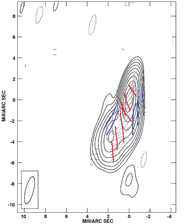
When first discovered in the active galactic nucleus (AGN) 1055+018 [1], “spine-sheath” polarization structure was quite unexpected. Early VLBI polarimetry experiments at 5GHz suggested that, depending on the jet’s angle to the line-of-sight, the image might be dominated by the “spine” or by the “sheath”, but wouldn’t show both at once (see [1]).
One possible explanation for an AGN with “spine-sheath” polarization structure is interaction of the jet with the surrounding medium, causing a deceleration of the plasma near the jet edges and stretching out the magnetic field along the jet, forming a shear layer. The polarization is strongest where the interaction is strongest. In this picture the orthogonal magnetic field is caused by a series of transverse shocks which are more highly polarized than regions between them [2, 1].
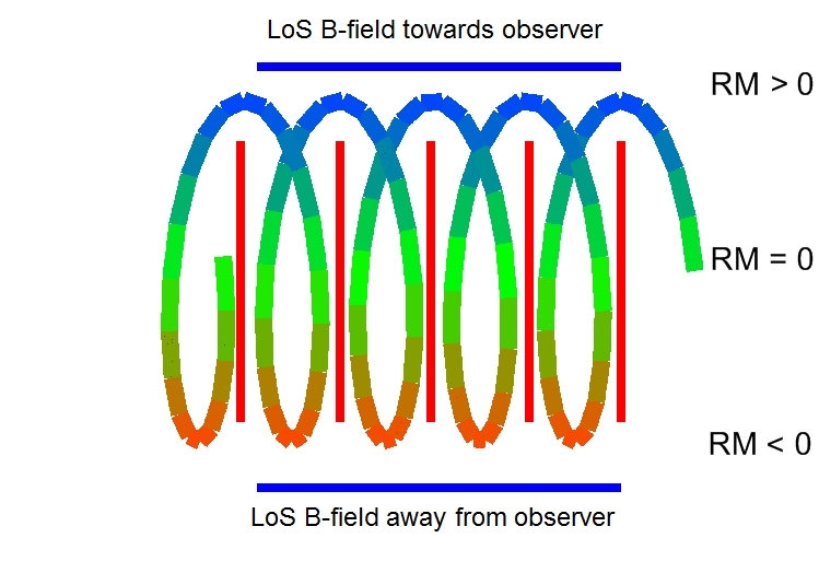
A second possible explanation is an overall helical magnetic field along the jet, where the projected toroidal component of the field is dominant at the jet axis, and the longitudinal field component becomes dominant at the jet edges [3, 4]. This explanation is simpler and does not require two independent mechanisms to work.
Figure 1 shows an example of “spine-sheath” polarization structure and how to explain such a structure with a helical magnetic field.
To investigate this phenomenon we are making use of the effect of Faraday Rotation.
2 Faraday Rotation
When a linearly polarized electromagnetic wave travels through magnetized plasma, the polarization angle rotates due to the different propagating speeds of left and right-circular polarized components of the wave. This is called Faraday Rotation. The amount of rotation is proportional to the square of the observing wavelength, , as well as the integral of the electron density and the line-of-sight component of the B-field, while its sign is determined by the direction of the line-of-sight B-field:
Where is the unrotated polarization angle, is the electron density and is the line-of-sight magnetic field.
We call the coefficient of the Rotation Measure (RM). Having simultaneous multifrequency observations, the RM can be easily determined by measuring the polarization angle for each pixel at each frequency and performing a linear fit on these. This also gives us the intrinsic (unrotated) polarization angle.
Thus, systematic gradients in Faraday Rotation across the jets of AGN can be interpreted as representing a systematic change in the line-of-sight component of a helical/toroidal B-Field (Figure 1).
3 Observations and results
24 AGN showing evidence for “spine-sheath” polarization structures were selected for multi frequency radio observations (4.6, 5.1, 7.9, 8.9, 12.9, 15.4 GHz) with the Very Long Baseline Array (VLBA). Here we present selected results for one of these two experiments. The observations were obtained with the Very Long Baseline Array (VLBA) on the 27th of September 2007. The data were calibrated and imaged in the NRAO AIPS package using standard techniques.
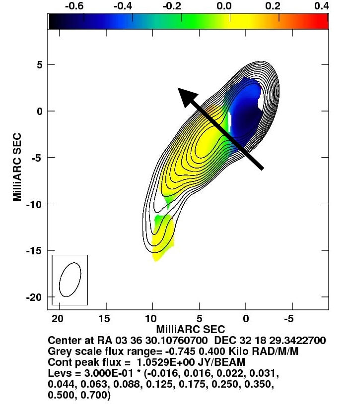
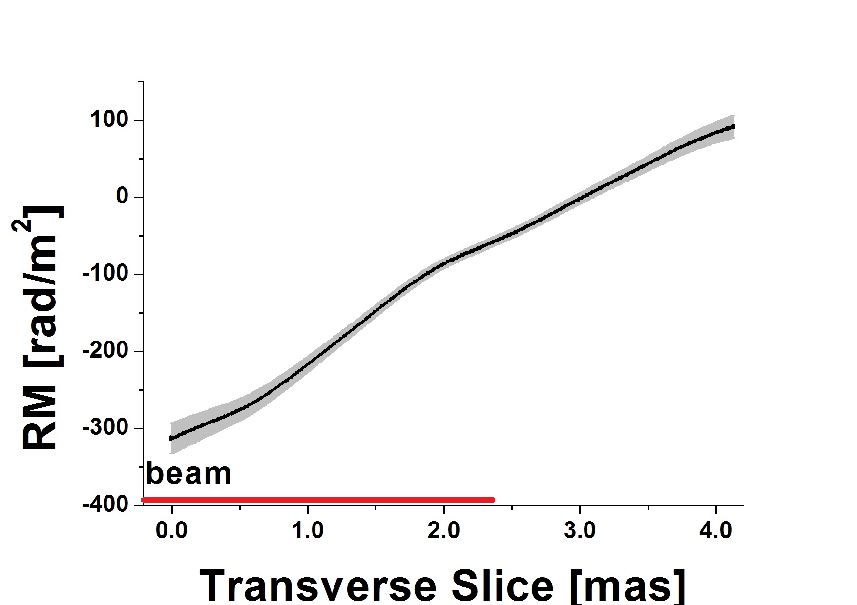
Analyzing their Rotation Measure (RM) distributions we have found some evidence for helical magnetic field structures in seven out of twelve objects. As an example, Figure 2 shows a transverse RM gradient across the entire resolved jet region of 0333+321. This is consistant with a helical/toroidal magnetic field structure surrounding the jet and confirms the results of Asada et al. [6], who found a very similar gradient in that source. The gradient of 0333+321 is slanted; this could be the result of a transverse RM gradient across and a decreasing RM along the jet, for example, due to a helical magnetic field combined with a fall-off of electron density/magnetic field strength with distance from the core.
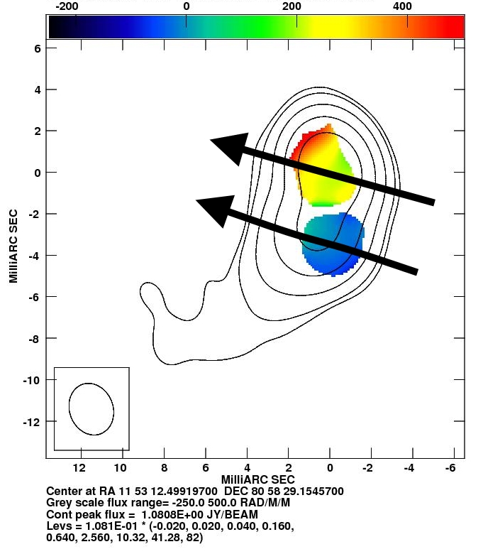
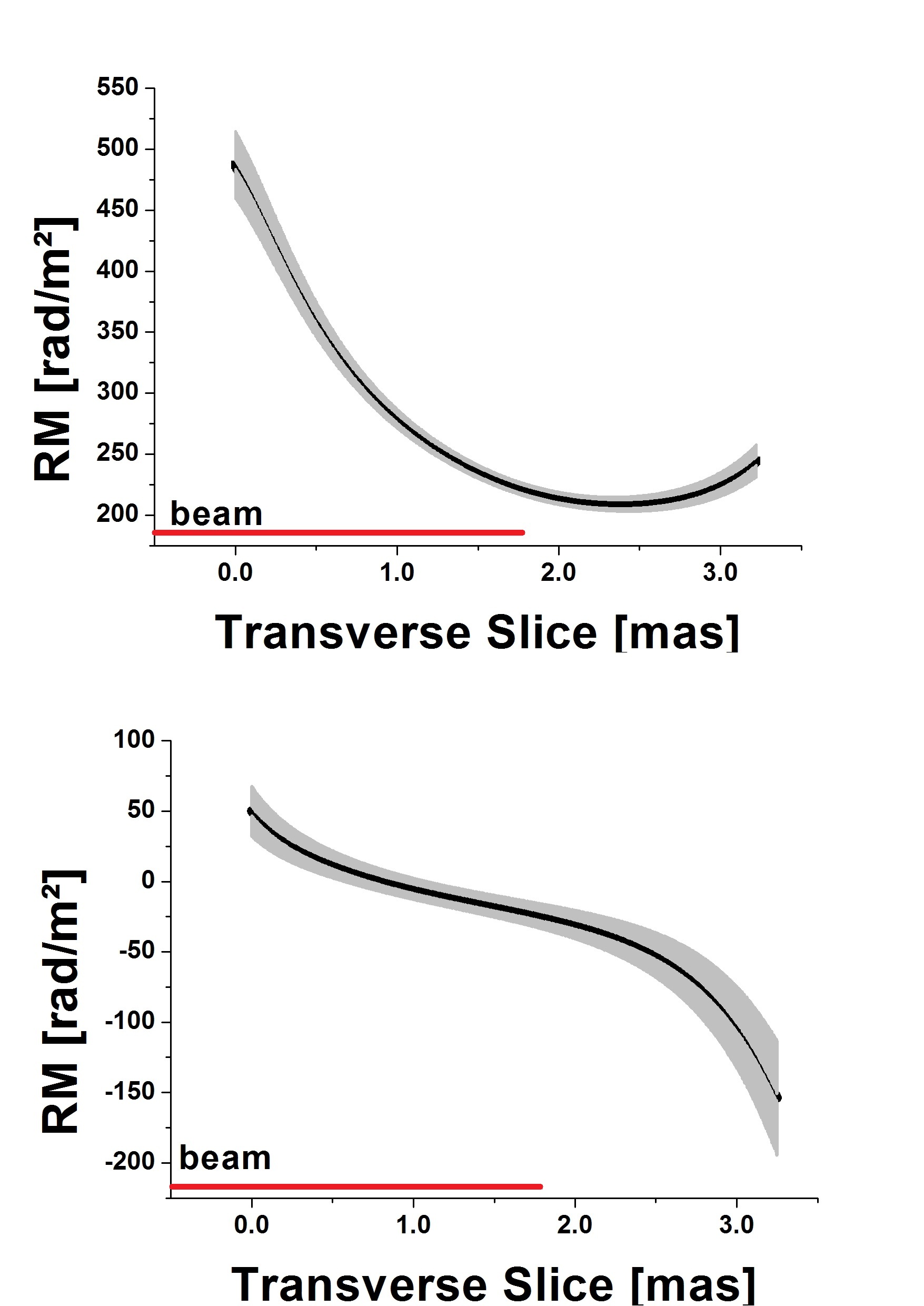
Another transverse RM gradient was found across the jet of 1150+812, see Figure 3.
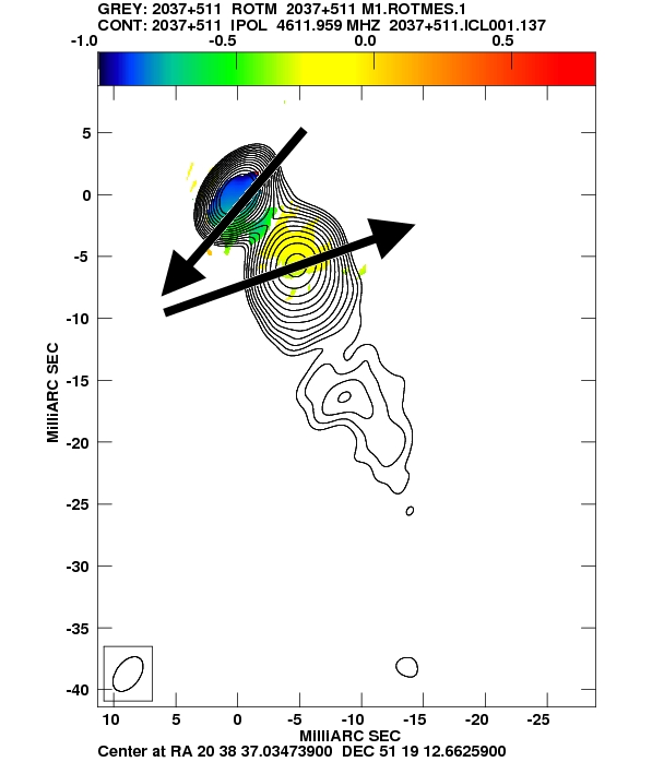
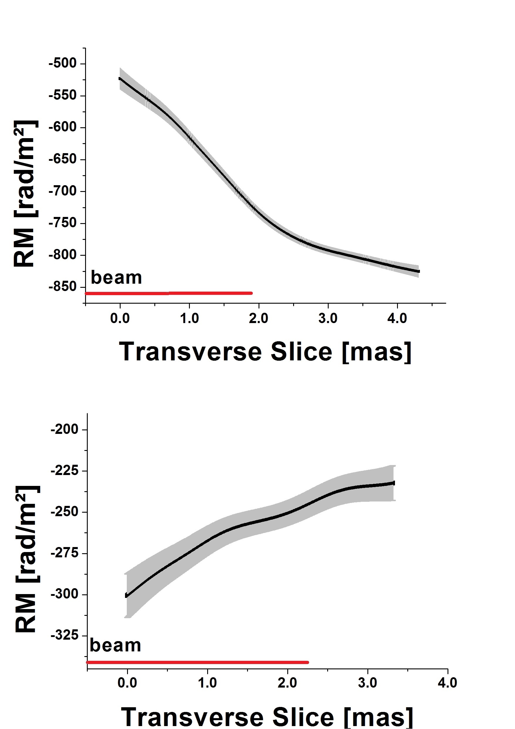
We have found three sources that show two oppositely directed transverse RM gradients at different distances from the core. They could be due to a “nested-helix” B-field structure, where the B-field emerging with the jet closes in the outer accretion disk [5]. In this picture the net RM gradient has contributions from both regions of helical field, and the dominant region determines the direction of the gradient. Figure 4 shows two oppositely directed transverse RM gradients in 2037+511, one in the core region and one about 10 mas from the core.
We have also found for our sources that the degree of polarization tends to be higher at the edges of the jet, which is expected for a helical magnetic field.
4 Discussion and Conclusion
We have found tranverse rotation measure gradients across several new sources and were also able to confirm the gradient found by Asada et al. [6] in 0333+321. We find some evidence for transverse RM gradients that may be associated with helical jet magnetic fields in 7 out of 12 “spine-sheath” AGN analysed. The simplest explanation for these transverse gradients is a helical magnetic field wraped around the jet, whose changing line-of-sight magnetic field components cause the observed gradients.
All our “spine-sheath” sources show an increase of fractional polarization towards the jet edges, which can also be explained by a helical magnetic field.
This provides evidence that their polarization structures are inherently assosiated with helical B-fields.
Our future work will include analysing 18-22cm VLBA polarization observations of several “spine-sheath” sources. We are also performing a Circular Polarization analysis using these data in collaboration with Vasiliy Vitrishchak, in order to search for connections between the circular polarization and RM gradients (see, e.g. [7]).
Acknowledgments.
Funding for this research was provided by Science Foundation Ireland.References
- [1] Attridge, J. M.,Roberts, D. H., & Wardle, J. F. C. 1999, ApJ, 518, 87
- [2] Wardle, J. F. C.,Cawthorne, T. V.,Roberts, D. H., & Brown,L. F. 1994, ApJ, 437, 122
- [3] Lyutikov, M.,Pariev, V. I., & Gabuzda, D. C. 2005, MNRAS, 360, 869
- [4] Pushkarev, A. B.,Gabuzda, D. C.,Vetukhnovskaya, Y. N., & Yakimov, V. E. 2005, MNRAS, 356, 859
- [5] Mahmud, M.,Gabuzda, D. C., & Bezrukovs, V. 2009, ArXiv e-prints
- [6] Asada, K.,Inoue, M.,Nakamura, M.,Kameno, S.,Nagai, H. 2008, ApJ, 682, 798
- [7] Gabuzda, D. C.,Vitrishchak V. M.,Mahmud, M, & O’Sullivan, S. P. 2008, MNRAS, 384, 1003