Numerical Simulations of Gravity-Driven Fingering in Unsaturated Porous Media Using a Non-Equilibrium Model
Abstract
This is a computational study of gravity-driven fingering instabilities in unsaturated porous media. The governing equations and corresponding numerical scheme are based on the work of Nieber et al. [Ch. 23 in Soil Water Repellency, eds. C. J. Ritsema and L. W. Dekker, Elsevier, 2003] in which non-monotonic saturation profiles are obtained by supplementing the Richards equation with a non-equilibrium capillary pressure-saturation relationship, as well as including hysteretic effects. The first part of the study takes an extensive look at the sensitivity of the finger solutions to certain key parameters in the model such as capillary shape parameter, initial saturation, and capillary relaxation coefficient. The second part is a comparison to published experimental results that demonstrates the ability of the model to capture realistic fingering behaviour.
CHAPWANYA AND STOCKIE \titlerunningheadSIMULATIONS OF GRAVITY-DRIVEN FINGERING \authoraddrMichael Chapwanya, Department of Mathematics and Applied Mathematics, University of Pretoria, 0002 Pretoria, South Africa. (m.chapwanya@up.ac.za) \authoraddrJohn M. Stockie, Department of Mathematics, Simon Fraser University, 8888 University Drive, Burnaby, British Columbia, V5A 1S6, Canada. (stockie@math.sfu.ca)
1 Introduction
The transport of water and dissolved contaminants within the vadose zone is extremely important in a wide range of natural and industrial applications including protection of groundwater aquifers, irrigation, flood control, and bioremediation, to name just a few. Many of these applications exhibit preferential flow in which gravitational, viscous or other forces initiate instabilities that propagate as coherent finger-like structures. In fingered flow, water is able to bypass a significant portion of the porous matrix and thus penetrate more rapidly than would otherwise be possible for a uniform wetting front; as a result, fingering can have a major impact on the transport of contaminants carried by an infiltrating fluid. A clear understanding of fingering phenomena can therefore be essential in the study of certain applications such as groundwater contamination.
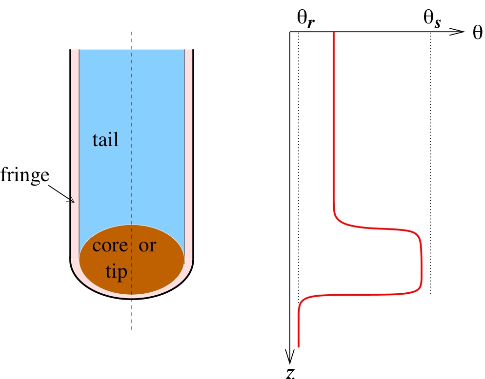
We focus in this work on preferential flow that is driven by gravitational forces arising from the difference in density between invading water and displaced air. The structure of a typical finger consists of a nearly saturated “tip” at the leading edge, behind which follows a “tail” region having a uniform and relatively low saturation (see Fig. 1). As the finger penetrates into the soil, the region immediately behind the tip drains somewhat causing pressure to decrease and preventing the finger core from widening, thereby allowing the unstable finger to persist in time. Experimental studies have provided additional insight into the detailed character of fingers and the physical mechanisms driving their formation, beginning with the work of Hill and Parlange (1972) and continuing to the present day with the work of authors such as Diment and Watson (1985), Glass et al. (1990), Selker et al. (1992a), Lu et al. (1994), Bauters et al. (2000), Yao and Hendrickx (2001), Wang et al. (2004) and DiCarlo (2004).
Various mathematical models have been developed to capture fingering phenomena (Philip, 1975; Parlange and Hill, 1976; DiCarlo et al., 2008) with many based on applying the Richards equation (RE) in combination with appropriate constitutive equations for soil properties. Techniques of linear stability analysis were applied to two-dimensional models by Saffman and Taylor (1958), Chuoke et al. (1959), and Parlange and Hill (1976), who derived stability criteria and analytical predictions for quantities such as finger width and velocity. Raats (1973) postulated a criterion for stability which stated that a wetting front is unstable if the velocity of the front increases with depth; this is clearly satisfied for some layered media as well as for water-repellent soils. Many analytical results have been compared to experiments by authors such as Glass et al. (1989b) and Wang et al. (1998), who found that no single analytical formula is capable of capturing the behaviour of the majority of soils. Other modifications and improvements to the theory have appeared more recently, such as Wang et al. (1998) who modified the work of Parlange and Hill (1976) to include dependence on the water- and air-entry pressures. A comprehensive review of stability results, including comparison to experiments, can found in de Rooij (2000). There has also been a great deal of recent effort on explaining gravity-driven fingering using models based on conservation laws (Eliassi and Glass, 2002; Nieber et al., 2003, 2005; Cueto-Felgueroso and Juanes, 2008, 2009a). A recent paper by Cueto-Felgueroso and Juanes (2009b) presents the first exhaustive stability analysis of a conservation law that leads to fingering in unsaturated flow, and a follow-up study by the same authors performs an extensive comparison to experiments as well as providing an excellent review of the current literature (Cueto-Felgueroso and Juanes, 2009a).
There has been a recent surge of interest in modelling fingering instabilities using extensions of the RE model, such as the work of Cuesta et al. (2000) and Cuesta and Hulshof (2003) who analyze non-monotonic travelling wave profiles that arise when dynamic capillary effects are incorporated. Both Eliassi and Glass (2001) and Nieber et al. (2005) identified a number of mechanisms that could give rise to gravity-driven fingering, including non-monotonicity in hydraulic properties, dynamic capillary effects and hysteresis. Egorov et al. (2003) provide an overview of the mathematical formulation showing that Richards equation is unconditionally stable even for heterogeneous media. Furthermore, Nieber et al. (2003) claim that dynamic (or non-equilibrium) effects are sufficient to cause formation of fingered flow, while persistence of fingers is dominated by hysteresis. In parallel with these developments, several novel mathematical models have been developed which incorporate these and other effects. A number of authors have investigated the use of non-equilibrium effects (Mitkov et al., 1998; Cuesta et al., 2000; Hassanizadeh et al., 2002; Helmig et al., 2007; Manthey et al., 2008) while others (DiCarlo et al., 2008) have been inspired by non-monotonicity to introduce extra terms in the RE that capture the “hold-back-pile-up” effect examined by Eliassi and Glass (2003). Non-equilibrium effects have also been studied in the context of two-phase flow by van Duijn et al. (2007), who used an extension of the Buckley-Leverett model to obtain non-monotonic profiles with both infiltration and drainage fronts. Sander et al. (2008) proposed a one-dimensional RE model including hysteresis and non-equilibrium capillary terms, which is very closely-related to the model studied in this paper. Adding to the controversy are experimental results such as DiCarlo (2007) which failed to find significant dynamic effects in gravity-driven infiltration. Notwithstanding the extensive literature on this subject, many open questions remain about which governing equations and constitutive relations are most appropriate for capturing preferential flows.
We will focus on a specific model called the relaxation non-equilibrium Richards equation (or RNERE) (Nieber et al., 2003, 2005) which incorporates both dynamic and hysteretic effects. These authors developed an iterative algorithm for integrating the governing equations numerically, and showed that their method is capable of generating finger-like solutions. The main drawback of this work was that it contained no concrete comparisons to experimental results. In this paper, we perform a more extensive suite of numerical simulations with the RNERE model and compare the results to published experimental studies. We also carry out a careful numerical convergence study and investigate the sensitivity of the model to changes in physical parameters and algorithmic aspects such as the choice of inter-block averaging for hydraulic conductivity. The results demonstrate that the RNERE model is capable of reproducing realistic fingering flows for a wide range of physically relevant parameters.
2 Mathematical Model
We begin by presenting the governing equations for the RNERE model as presented by Nieber et al. (2003), while at the same time reviewing earlier work on fingered flow in porous media. The RE is written in mixed form as
| (1) |
where represents time [], is the volumetric water content or saturation [], and is the water pressure head []. The asterisks are used here to indicate dimensional quantities, and will be dropped shortly when the equations are non-dimensionalized. Hydraulic conductivity [] is denoted by , which is assumed to be a given function of water content in the case of unsaturated flow. The spatial domain is two-dimensional with coordinates , where represents the vertical direction and is measured positive downwards and is measured horizontally. This form of the RE is called “mixed” because both saturation and pressure appear as dependent variables, and it is preferred to both the –based form (which becomes singular when the flow is fully saturated) and the –based form (which leads to large mass conservation errors when discretized) (Celia et al., 1990).
Many models of flow in porous media combine the RE with an equilibrium constitutive relation of the form , which assumes that transport properties relax instantaneously to their equilibrium values as water content varies during a wetting or drying process. This is a reasonable approximation under certain circumstances; however, there is now evidence from both laboratory experiments (DiCarlo, 2004) and stability analyses (Nieber et al., 2005) that suggests the RE by itself is unable to capture the non-monotonic profiles observed in fingering instabilities and so it lacks some critical physical mechanism. An illustration of a typical solution profile is shown in Fig. 1, wherein a downward-propagating finger is led by a nearly-saturated “tip” region that leaves behind it a “tail” region having a lower water content.
An earlier attempt at simulating fingered flow using the equilibrium RE was made by Nieber (1996) who incorporated hysteretic effects and found that fingers only appeared when a downwind-weighted mean was used for hydraulic conductivity. Eliassi and Glass (2001) concluded that the finger-like profiles obtained in these simulations did not represent solutions of the actual model equations, but rather were numerical artifacts arising from local truncation errors due to the particular choice of downwind mean.
Based on physical arguments, Hassanizadeh and Gray (1993) advocated that a non-equilibrium version of the capillary pressure relationship should be employed in situations where the relaxation time is comparable to other time scales in the flow. This work inspired Nieber et al. (2003) to propose their RNERE model in which the RE was supplemented by a relaxation equation of the form
| (2) |
where represents the equilibrium water pressure head [], is the density of water [], is the gravitational acceleration [], and is a suitably-chosen capillary relaxation function []. They presented numerical simulations of finger-like instabilities and concluded that a non-equilibrium effect is sufficient to initiative the instabilities and that hysteresis is necessary to sustain the fingers once formed. In most cases, is assumed either to be a constant (Hassanizadeh et al., 2002; Manthey et al., 2008) or else a separable function of dynamic capillary pressure and water content (van Duijn et al., 2004; DiCarlo, 2005; Nieber et al., 2005), although the proper choice of functional form for the relaxation function remains an open question. We note that Eq. (2) should be viewed as an equation for the dynamic capillary pressure rather than an evolution equation for ; indeed, when (2) is substituted into Eq. (1), the resulting PDE takes the form of a third-order evolution equation for which is of pseudo-parabolic type (King and Cuesta, 2006).
Before proceeding further, we briefly mention several other attempts at incorporating non-equilibrium effects into the RE in more general contexts not directly related to fingering. Mitkov et al. (1998) took a phase-field model for solidification and adapted it to porous media flow; their model contains a phenomenological term in which the constants have no direct relationship to the physics. Barenblatt et al. (2003) suggested an alternate approach in which dynamic effects are incorporated into both capillary pressure and hydraulic conductivity through an “effective saturation” variable. Three further variants of the RE called the hypo-diffusive, hyperbolic and mixed forms were proposed with an aim to reproducing the “hold-back-pile-up” effect observed in experiments (Eliassi and Glass, 2003; DiCarlo et al., 2008). Analytical and numerical results suggest that many of these approaches show promise, but the proper choice of model remains an open question.
To complete the mathematical description of the RNERE model equations (1) and (2), the equilibrium pressure and hydraulic conductivity must be specified as functions of water content. These quantities are customarily expressed in terms of the normalized water content
| (3) |
where and are the saturated and residual (or irreducible) water contents, respectively; is commonly referred to as the effective saturation or simply saturation. In a partially saturated porous medium, the saturation variable satisfies , where represents the porosity, so that always lies between 0 and 1. We adopt the widely-used van Genuchten–Mualem relationships for and (van Genuchten, 1980), which are monotonic functions containing several empirical fitting parameters that are used to fit with experimental data for a variety of soil and rock types. Saturation and pressure are related at equilibrium by
| (4) |
where and are parameters that govern the shape of the capillary curves.
In practice, is a hysteretic function wherein the inverse capillary length [] and shape parameter differ depending on whether the current state is evolving along the main wetting curve () or main drying curve (). The corresponding hydraulic conductivity is given by
| (5) |
where represents the fully saturated value (at ). The RE (1) becomes degenerate when , although we never have to deal explicitly with this issue because we always choose a value of initial saturation greater than the residual value . Furthermore, we have not encountered values of the reduced saturation in excess of 1 (for which the conductivity is undefined in Eq. (5)) and so the computed solution remains within the physical limits . Details of the precise form of the hysteresis model to be used will be provided later in Section 3.
2.1 Non-Dimensionalization and Choice of
In this section, the equations are reduced to dimensionless form using the transformations
| (6) | |||
where (the reciprocal of the van Genuchten parameter for the main wetting curve) has been used as the natural length scale. The governing equations (1), (2), (4) and (5) then reduce to
| (7) | ||||
| (8) | ||||
| (9) | ||||
| (10) |
where the dimensionless capillary relaxation function is
and and represent the hysteretic constitutive relations (which depend on the wetting/drying state ). It will prove convenient when describing the numerical algorithm to recast the time-derivative in Eq. (8) in terms of the equilibrium capillary pressure as
| (11) |
where .
Following Nieber et al. (2005) (who was motivated by the experiments of Selker et al. (1992b)) we assume that is a function of only
| (12) |
where , and are constants and . Nonetheless, the appropriate choice of functional dependence for on the state variables remains an open question. Various other functional forms have been proposed by DiCarlo (2005) and Sander et al. (2008), all of which we find leads to similar fingering patterns provided that as and that the magnitude of the relaxation parameter is comparable. On the other hand, if is taken to be a constant then no fingers were observed in our simulations, hence suggesting that it is essential to have a solution-dependent .
2.2 Boundary and Initial Conditions
Inspired by the geometry most commonly employed in experimental studies, we consider a two-dimensional rectangular domain as shown in Fig. 2 that has width and height (both dimensions having been non-dimensionalized by scaling with like the other lengths in Eq. (6)).
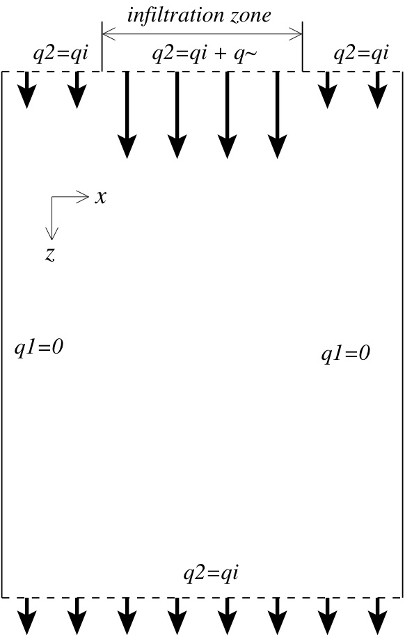
The initial saturation is assumed constant throughout the domain, . No-flux conditions are imposed along side boundaries and specified inflow (outflow) conditions are given along the top (bottom) boundaries, both of which we express in terms of the dimensionless flux variable
| (13) |
where and represent the components of the flux vector. This last equation is a statement of Darcy’s law for unsaturated flow and is rescaled according to , where the original physical flux has units of . The fluxes on the left, right, and bottom boundaries are given respectively by
| (14) |
where represents a constant gravity-driven background flux that corresponds to the initial saturation . The specification of such a background flux is essential when the porous medium is not air-dried, such as is the case for most naturally occurring soils. In order to drive the formation of fingers, the flux along the top boundary is specified by some constant background flux plus an infiltration flux that is imposed along a strip of width ,
| (17) |
Following Nieber et al. (2003), this infiltration flux is written as the sum of an average value plus a small sinusoidal perturbation
| (18) |
where represents the amplitude of the perturbation and the frequency (for a positive integer). We note that the size and number of fingers actually observed in simulations is relatively insensitive to the choice of perturbation parameters and .
We close with a brief mention of a common result on stability of gravity-driven vertical infiltration flow, wherein viscous forces tend to stabilize the flow while gravitational forces are the destabilizing influence. Extensive work on stability has been reported by many authors, including Philip (1975), Parlange and Hill (1976), Wang et al. (1998) and de Rooij (2000). It is known that unstable flow will occur if the hydraulic conductivity increases with depth, which translates into a requirement that the inflow at the top boundary satisfies .
3 Solution Algorithm
We next describe the algorithm developed by Nieber et al. (2003) for solving the RNERE problem in Eqs. (7) and (9)–(11), which is an iterative strategy that employs a finite volume spatial discretization in space and a semi-implicit time-stepping scheme. The domain is divided into an rectangular grid, with cell dimensions and in the – and –directions respectively. The discrete saturation approximates the solution at cell centers , and similarly for the pressure head . Employing an implicit backward Euler discretization for the time derivative in Eqs. (7) and (11) and centered second-order differences in space, the discrete equations become
| (19) |
and
| (20) |
for and . The time step is denoted by and the “hat” notation and refers to a solution value at the previous time step.
It is worth mentioning that although an upwind difference might normally be advocated for the convective (gravitational) term in Eq. (19), we have chosen to use a centered difference for consistency. In practical computations, we observe no difference between an upwind or centered difference treatment of the term because capillary effects dominate in this problem.
In contrast with the cell-centered saturation and pressure head unknowns, the hydraulic conductivity values and are located at cell edges. Since the conductivity depends on saturation which is not available at cell edges, it must be approximated using some weighted mean of nearby values of saturation; the specific choice of averaging method will be considered in detail in Section 4.1. The capillary relaxation function in Eq. (12) is replaced by the regularized function , where the cut-off parameter prevents from becoming zero and hence avoids a singularity in Eq. (20).
The difference stencils in Eq. (19) involve values of pressure head for and , located at points lying one-half grid cell outside the physical domain. These “fictitious values” are eliminated using the flux boundary conditions (14)–(18) as follows. First, the flux is discretized along cell edges, with the -component (on side boundaries ) being approximated by
| (21) | |||
| and the -component (along horizontal boundaries ) by | |||
| (22) | |||
Then the boundary conditions for and are used to express fictitious point values in terms of known values of pressure head at interior points, which can then be used in Eq. (19).
We now describe the iterative scheme for solving the nonlinear system (19), which can be written more succinctly in matrix-vector form as
| (23) |
where and are vectors containing the discrete approximations of and respectively, and is a symmetric pentadiagonal matrix whose entries are nonlinear functions of saturation. Nieber et al. (2003) did not base their iterative solution strategy directly on Eq. (23) because the matrix is not positive definite; instead, they proposed the following modified iteration
| (24) |
where represents the iteration number and is a diagonal matrix whose entries are given by
| (25) |
This approach has the advantage that the iteration matrix is both symmetric and positive definite and thus has much better convergence properties. We now outline the iterative procedure within each time step, assuming that each iteration begins with , , and :
- Step 1.
-
Solve the relaxation equation
for .
- Step 2.
-
Update the saturation using .
- Step 3.
-
Evaluate the matrices and at , and . Then solve the linear system (24) for and let .
- Step 4.
-
If the current solution satisfies the convergence criterion , then stop. Otherwise, increment and return to Step 1.
Following Eliassi and Glass (2001), we employ a variable time step which is initialized to and then replaced at the end of each time step by , where the maximum allowable step is given by the CFL-like condition . This approach minimizes initial start-up errors by taking a relatively small time step initially, which then increases gradually to . The algorithm just described is implemented in Matlab and uses the built-in preconditioned conjugate gradient solver pcg to invert the linear system in Step 3.
We stress that this is only one possible choice of algorithm and that many other strategies have been proposed for solving the coupled system of equations for saturation and capillary pressure. For example, Cuesta (2003) and Cuesta and Pop (2009) have analyzed a number of algorithms (including the one described above) in the context of the Burgers equation, supplemented by dynamic capillary effects.
An important aspect of our RNERE model is the singularities that occur when (where the iteration matrix fails to be positive definite) and (where the derivative of the hydraulic conductivity becomes unbounded). A number of methods have been proposed in the literature (e.g., Starke (2000); Pop (2002)) to regularize coefficients in the governing equations in order to avoid these singularities. We have not made use of any such regularization here because in practice, we find that the computed saturation never reaches the limiting values of 0 or 1. Nonetheless, it may be worthwhile in future to consider implementing such a regularization approach to improve the efficiency and robustness of the algorithm in cases where conditions approach the saturated and unsaturated limits.
3.1 Implementation of Hysteresis
An integral component of the RNERE algorithm is the specification of the hysteretic state, which is potentially different at every point in the domain and depends on the local saturation and wetting history. We have chosen to implement a closed-loop hysteresis model described by Scott et al. (1983) and implemented by Eliassi and Glass (2003) wherein all curves have the same values of residual and saturated water content (0 and 1 respectively in our dimensionless variables). We have also taken the shape parameters for the wetting and drying curves to be constant and equal (), so that the various curves differ only in their value of (although in general, the values of should also depend on the current hysteretic state).
Following Eliassi and Glass (2003), the main drying curve is written while the scanning drying curves are given by the scaled equation
| (26) |
where and denote respectively the saturation and pressure reversal points along the previous wetting curve. Similarly, the main wetting curve is while the scanning wetting curves are written
| (27) |
where
| (28) |
and and are the reversal points along the previous drying curve.
The main drying and wetting curves are unique, while the scanning curves differ depending on the reversal points which are determined as follows. At each point in space, we maintain the current state (wet or dry) as well as the previous reversal point . To avoid problems with convergence in the iterative scheme, the hysteretic state is updated only at the end of each time step and not within a -iteration. To detect a reversal point along a local drying or wetting curve, we test whether the time rate of change of saturation has reversed sign between the current () and previous () time steps, which is equivalent to checking that where . To avoid spurious wet/dry oscillations between successive time steps, we impose the additional constraint that , where is a reversal threshold. If both of these criteria are met, then a flow reversal has occurred and the current state is switched to either wetting (if ) or drying (if ), and the current values for the reversal point are updated. The appropriate scanning curve – either Eq. (26) or (27)–(28) – is then used to determine the capillary pressure as a function of saturation.
4 Numerical Simulations
To investigate the relevance of the proposed model and the accuracy and efficiency of the numerical algorithm, we consider a “base case” corresponding to a 14/20 grade sand studied experimentally by Glass et al. (1989b). The parameters listed in Table 1 are taken directly from their paper, with the exception of , and , whose values are justified in Sections 4.4–4.6.
The computational domain is taken to be a rectangle of width and height in dimensionless units, where is chosen slightly larger than the actual infiltration width used in experiments in order to minimize boundary effects. Unless otherwise noted, the domain is discretized using a uniform grid having and points in the and directions respectively. All simulations were performed on a Mac Pro with 23 GHz processor and 8GB RAM, with a typical run requiring approximately hours of computation time.
| \tablelineSymbol | Description | Value | Units |
| \tableline | Capillary shape parameter | 12 | – |
| Inverse capillary length | 35 | ||
| Initial water content | 0.01 | ||
| Saturated water content | 0.42 | ||
| Residual water content | 0.075 | ||
| Saturated conductivity | 0.063 | ||
| Permeability | |||
| Water entry pressure | |||
| \tableline |
| \tablelineSymbol | Description | Value |
| \tableline (a) Parameters from Glass et al. (1989b) – “base case”: | ||
| Capillary shape parameter | 12.0 | |
| Inverse capillary length (wetting) | 1.0 | |
| Inverse capillary length (drying) | 0.5 | |
| Initial water content | 0.01 | |
| Relaxation coefficient | 0.1 | |
| Relaxation exponent | 1 | |
| Relaxation parameter | 0 | |
| Hysteretic reversal criterion | ||
| Relaxation cut-off | 0.04 | |
| Background flux | ||
| Infiltration flux | 0.14 | |
| Perturbation amplitude | 0.01 | |
| Perturbation frequency | 5 | |
| Infiltration source width | 10.5 | |
| End time | 77 | |
| Domain height | 35 | |
| Domain width | 14 | |
| (b) Modifications for Nieber et al. (2003) (Figs. 8 & 9): | ||
| Capillary shape parameter | 7.0 | |
| Initial water content | 0.1 | |
| Relaxation coefficient | 5.0 | |
| Infiltration flux | 0.2 | |
| End time | 96 | |
| Domain height | 60 | |
| Domain width | 30 | |
| (c) Modifications for DiCarlo (2004, Tab. 1) for 20/30 and 30/40 sands (Fig. 4.7): | ||
| Capillary shape parameter | 6.23 / 10.0 | |
| Initial water content | 0.001 | |
| Domain height | 7.08 / 6.92 | |
| Domain width | 0\tablenotemarka | |
| \tableline | ||
aDiCarlo’s experimental soil columns measure less than one finger width in diameter, so that the flow is essentially one-dimensional; we perform “quasi-1D” simulations by taking only two grid points in the –direction.
A sample computation with the base case parameters is shown in Fig. 3, which depicts the progression of the wetting front at a sequence of equally-spaced times. In these plots (as well as the other plots and tables that follow) all quantities are expressed in dimensionless form. The plotted contours of saturation correspond to a value of equal to 25% of the finger tail saturation, which we have found gives a good representation of the finger size and shape. The structure of the individual fingers is seen more clearly in the saturation map given in Fig. 4, where each concentrated finger tip is followed by a tail region of roughly constant saturation. The “capillary fringe” region, depicted schematically in Fig. 1, is evident as a narrow zone of rapid saturation change surrounding each finger. The finger tip and tail are evident in this plot and the shape of each finger is in qualitative agreement with the generic profile sketched in Fig. 1.
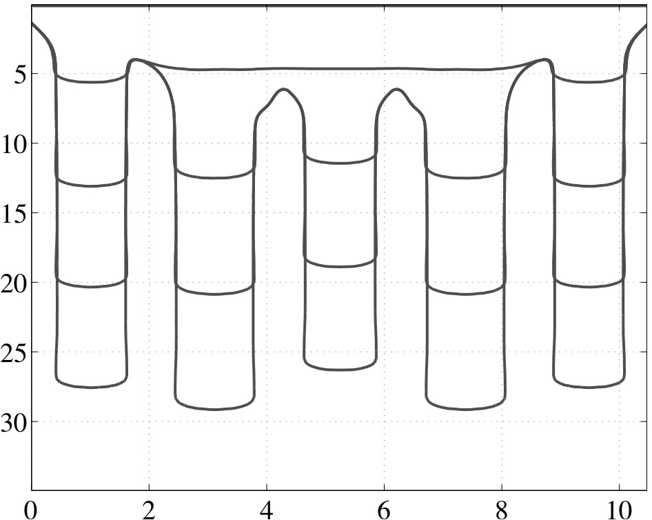
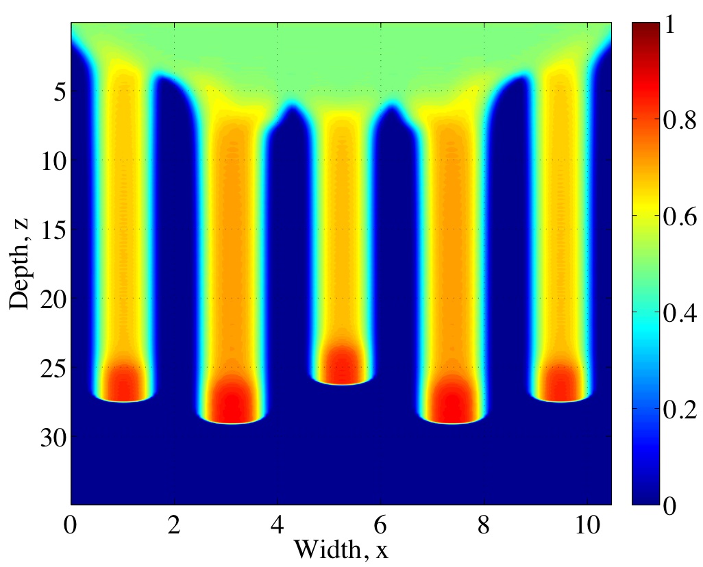
To illustrate the importance of dynamic and hysteretic effects in the RNERE model, we show in Fig. 4 how the wetting front differs when either of these effects is left out. When the dynamic term is omitted from the saturation equation (see Fig. 4(a)) fingering instabilities clearly fail to be initiated. Conversely, when hysteretic effects are left out (see Fig. 4(c)) protrusions begin to form at the wetting front but they never actually develop into full-blown fingers. These observations are consistent with the claim of Nieber et al. (2003) that dynamic capillary effects are responsible for the initiation of fingering instabilities, while hysteresis is required to sustain the fingers in time.
![[Uncaptioned image]](/html/1005.3297/assets/method_sumplots.jpg)
In the following sections, we present an extensive suite of numerical simulations that address the following four issues:
-
•
choosing an appropriate mean for the estimation of inter-block hydraulic conductivity values;
-
•
determining the dependence of the numerical solution on grid resolution, and comparing to previously published simulations;
-
•
measuring the sensitivity of the solution to certain key parameters: shape parameter (), dynamic relaxation coefficient () and initial saturation (); and
-
•
comparing simulated results to previously published experimental data.
In addition to providing plots of saturation plots, we will also report quantities such as finger width (), finger velocity (), number of fingers (), and average volume flow rate through each finger (), all of which vary depending on the value of the infiltration flux . When multiple fingers are present and a specific quantity varies from finger to finger, we report the average value over all fully-developed fingers.
4.1 Choice of Mean for Inter-Block Conductivity
As mentioned in Section 3, the discrete equations require values of hydraulic conductivity at cell edges ( and ) whereas the values of saturation on which depends are defined at cell centers; therefore, some form of averaging is usually necessary. It is well known that discrete approximations of the RE can be very sensitive to the choice of inter-block averaging used for hydraulic conductivity (Belfort and Lehmann, 2005). A number of different approaches have been advocated in the literature, for instance using arithmetic (van Dam and Feddes, 2000), geometric (Haverkamp and Vauclin, 1979), harmonic (Das et al., 1994), and Darcian-weighted means (Warrick, 1991). Cardwell and Parsons (1945) showed that the effective permeability for a heterogeneous porous medium must lie somewhere between the harmonic and arithmetic mean values. Furthermore, Warren and Price (1961) used Monte Carlo simulations of random media to show that the expected value of conductivity for a heterogeneous system is given by the geometric mean.
Of particular interest in this paper is the case where the conductivity undergoes large variation between grid cells owing to the presence of sharp wetting fronts at finger boundaries. Although a straightforward analytical argument indicates that the harmonic mean is the appropriate mean to use in such situations in 1D (Gutjahr et al., 1978), this is not the case in higher dimensions where many computational studies indicate that the harmonic average yields results that are inferior to those using other averaging methods (Haverkamp and Vauclin, 1979; Belfort and Lehmann, 2005; Pinales et al., 2005). Extensive comparisons have been drawn using measures such as resolution and stability of the wetting fronts, sensitivity to grid refinement, and robustness over a wide range of soil types and physical parameters. There remains a significant degree of controversy over which averaging procedure is best in practice, and to date no single mean has been found to be superior in all circumstances.
In this section, we compare results using the arithmetic and geometric means for hydraulic conductivity, which we have found are the most common means utilized in computations. Values of conductivity along vertical cell edges are determined as follows
| Arithmetic mean: | |||
| Geometric mean: |
with similar formulas for along horizontal cell edges. Problem parameters are taken from simulations presented by Nieber et al. (2003), which are identical to those for our base case described earlier, except for a few differences indicated in Table 4(b). The same set of parameters will also be considered in the following two sections. Our model is identical to Nieber et al.’s, except for a slight difference in the implementation of capillary hysteresis.
The results for the geometric mean are shown in Fig. 6 for five different choices of grid resolution (, , , and ), and the solution has clearly converged to a wetting profile with 4 well-defined fingers even on a grid. In contrast, Fig. 7 demonstrates that simulations with the arithmetic mean converge more slowly, and the results on the finest grid are still not fully converged. These simulations are consistent with those of Zaidel and Russo (1992), who found that use of the arithmetic mean introduces excessive smearing in wetting fronts and underestimates saturation values relative to the geometric mean. Based on these results, we conclude that the geometric mean is superior for the problem under consideration, which is also consistent with the a number of previous studies (Haverkamp and Vauclin, 1979; Hornung and Messing, 1983; Belfort and Lehmann, 2005). Consequently, we have chosen to apply the geometric mean in all remaining computations in this paper.
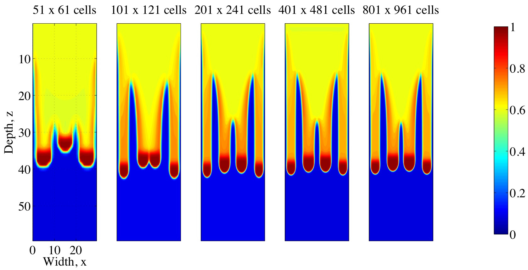
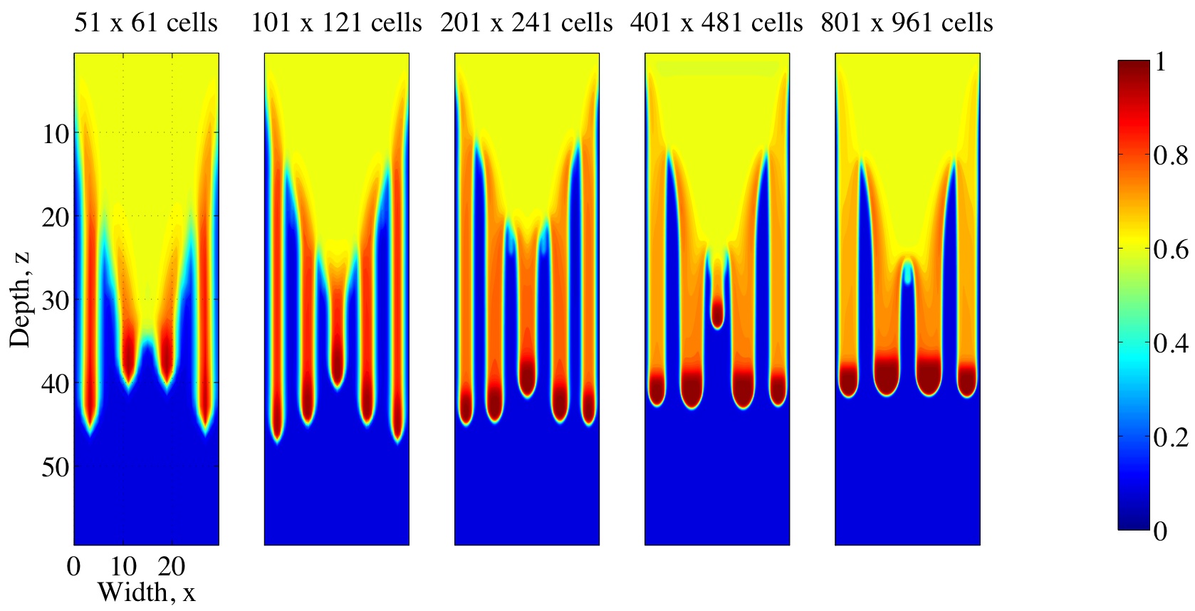
4.2 Grid Refinement Study
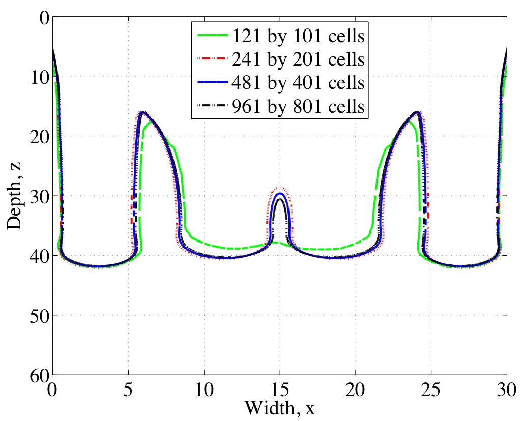
To ensure that the numerical solution does converge with the expected second order accuracy, simulations were performed on a sequence of successively refined grids of size to cells. The latter represents the finest resolution possible owing to memory restrictions on the computing equipment readily available to us. The grid resolution and physical parameters in this case were chosen to correspond to the numerical simulations of Nieber et al. (2003).
The solution on the finest grid is treated as the “exact solution” and the error is estimated using the norm of the difference between exact and computed values of saturation. The resulting absolute errors are summarized in Table 3 from which it is clear that the solution converges as the grid is refined; furthermore, the order of convergence is close to the expected value of 2. Fig. 8 depicts saturation contours corresponding to various grid refinement levels and clearly demonstrates the convergence of the numerical solution.
| No. of cells () | error | Ratio | Order |
|---|---|---|---|
| 10.59 | 3.52 | 1.82 | |
| 3.01 | 3.82 | 1.93 | |
| 0.79 | 4.31 | 2.11 | |
| 0.18 | – | – |
4.3 Comparison with Nieber et al.’s Computations
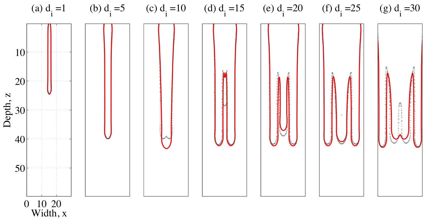
We now investigate the effects of grid resolution in more detail by way of a direct comparison with simulation results reported by Nieber et al. (2003). We focus on their second set of simulations (c.f., their Fig. 8), using different values of the infiltration width (, 5, 10.5, 15, 20, 25 and 30) and grid resolutions of and . Our results are summarized in Fig. 9 from which we observe a close match with Nieber et al. (2003, Fig. 8) in terms of both number of fingers and saturation levels. There are slight differences between finger widths and velocities, but we attribute these to our alternative implementation of capillary hysteresis. We emphasize the discrepancies between our high and low resolution results for values of , 15 and 30, which stresses the importance of using a sufficiently resolved grid in these fingering computations. It is particularly important to use a higher grid resolution in situations such as that are close to a “transitional phase” where in this case the solution exhibits somewhere between three and four fingers. We also stress the importance of performing a careful convergence analysis as part of any numerical study of fingering to ensure that the features being simulated are a true representation of actual fingering instabilities of the governing equations.
4.4 Sensitivity to Capillary Shape Parameter,
In the next three sections, we switch to the base case and investigate the sensitivity of the solution to changes in a number of important parameters. No value is provided by Glass et al. (1989b) for the capillary shape parameter appearing in the van Genuchten–Mualem relationships (9) and (10), and so we look for guidance in related experimental studies on sandy soils. The values for reported in the literature exhibit significant variability, lying anywhere between 3 and 20 even for porous media having similar coarseness and wettability (e.g., Schroth et al. (1996); Nieber et al. (2000)). The larger values of typically correspond to water-repellent soils in which fingers are more likely to form, while smaller values indicate a reduced tendency to generate fingering instabilities. Consequently, it is important in any modelling study of fingering to understand the effect of changes in on the character of the solution.
In Fig. 4, we present simulations for several values of lying between 4 and 15, while all other parameters are set to the base case values. In all simulations except for , the solution exhibits well-defined fingers having the characteristic non-monotonic saturation profile down the central axis of each finger. Furthermore, increasing leads to an increase in the tip/tail saturation ratio and a decrease in finger width and finger flux, as expected; in other words, fingers are more diffuse for smaller while finger boundaries become sharper when is increased.
![[Uncaptioned image]](/html/1005.3297/assets/n_sumplots.jpg)
The value of used in the base case is characteristic of highly water-repellent soils, which is corresponds to the other experimental and numerical studies we are most interested in.
4.5 Sensitivity to Initial Saturation,
A study of the effect of the initial saturation on our numerical solution is warranted for two reasons. First of all, the nature of fingering instabilities and the properties of individual fingers (such as finger width and velocity) can be very sensitive to the choice of initial water content, as evidenced by several experimental studies (Diment and Watson, 1985; Bauters et al., 2000; Wang et al., 2003). Finger shape and size depends strongly on the initial wetting state; in particular, vertical infiltration into a soil with larger initial saturation tends to generate fingers that are more diffuse than when the soil is dry. Secondly, as with the capillary shape parameter , the value of is frequently omitted in the list of parameters reported in experimental studies (e.g., Glass et al. (1989b)).
We therefore perform a series of simulations using various choices of initial saturation between 0.001 and 0.075, holding the infiltration flux constant. The results are summarized in Fig. 4 from which we observe that the number of fingers increases as is increased. In fact, the spacing between fingers also decreases to the extent that when , the individual fingers merge together to form a single finger.
| (a) | (b) | (c) | (d) | |
|---|---|---|---|---|
![[Uncaptioned image]](/html/1005.3297/assets/sat_sumplots.jpg)
![[Uncaptioned image]](/html/1005.3297/assets/sat_sumplots_map.jpg)
As and finger width increase, we notice from the saturation maps in Fig. 4 that the maximum finger tip saturation decreases while the finger velocity remains relatively unchanged; this behaviour can be justified using a simple mass conservation argument. Most of these computed trends are consistent with experiments, the exception being the finger velocity for which some experimental studies exhibit a stronger dependence on (e.g., Bauters et al. (2000)).
We mention in closing this section that in the absence of a given value of initial saturation in Glass et al. (1989b), we have chosen for the base case. This value lies within with the typical range of residual saturations seen in experiments for similar soils, and also generates fingers with a tip saturation that is consistent with values reported by DiCarlo (2004).
4.6 Sensitivity to Capillary Relaxation Coefficient,
Although several recent models for gravity-driven fingering have used a capillary relaxation term to incorporate dynamic effects, there remains a great deal of uncertainty in both the functional form and overall magnitude of the relaxation coefficient (Juanes, 2008; Manthey et al., 2008). Stauffer (1978) derived an empirical estimate based on the Brooks–Corey model for conductivity and capillary pressure (in lieu of the van Genuchten–Mualem relationships used here) that takes the following form
| (29) |
where is a fitting parameter, is the fluid viscosity, and and are the Brooks–Corey parameters. Recent experimental results suggest that the values of for sandy media can range between 0.006 and 20, so that lies between and (Manthey et al., 2008).
We have run a number of simulations using the functional form for given in (11) and with the scaling constant varying between 0.01 and 1.0. The resulting saturation is depicted in Fig. 4,
![[Uncaptioned image]](/html/1005.3297/assets/tau_sumplots.jpg)
from which it is evident that has a strong influence not only on the number of fingers but also on finger width and velocity. If is taken very small (less than 0.001) then dynamic effects become negligible and finger formation is suppressed. If, on the other hand, is taken larger then the finger tip saturation tends to increase which in turn reduces the number of fingers.
For the purposes of the base case, we have chosen an intermediate value of which gives a range of that is centered on the empirical estimate in Eq. (29), and which also corresponds well to the range of experimental values reported in the literature.
4.7 Comparison with DiCarlo’s Experiments
In this section we consider the experimental results reported by DiCarlo (2004), who studied the importance of non-equilibrium effects on finger formation in sandy porous media. These experiments investigated the effect of changes in infiltration flux, initial saturation, and porous media properties on the resulting saturation profiles. DiCarlo also proposed an RE-based model which neglected hysteretic effects, but did include a dynamic capillary term (as in our Eqs. (7)–(8)) with a number of different forms for the dynamic relaxation coefficient , including a constant and various power-law forms similar to Eq. (12). The correspondence between his numerical simulations and experiments (in terms of finger tip saturation) was less than satisfactory; in particular, although a reasonable fit was obtained for the tip saturations when was a power law function, the wetting front ahead of the finger tip was much too diffuse.
(a) 20/30 san
![[Uncaptioned image]](/html/1005.3297/assets/dicarlo_tip_tail2030_mod.jpg)
(b) 30/40 sand
![[Uncaptioned image]](/html/1005.3297/assets/dicarlo_tip_tail3040.jpg)
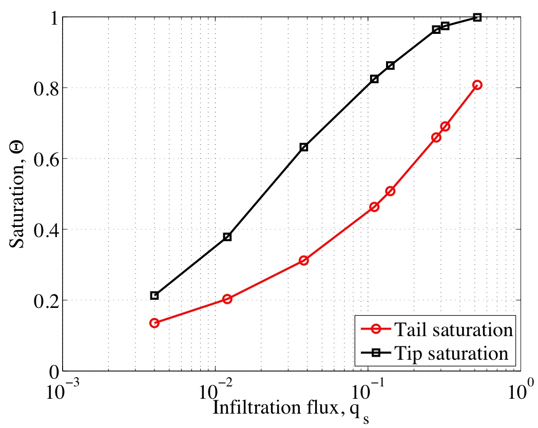
We focus primarily on DiCarlo’s experimental and numerical results for 20/30 sands which are reproduced in Fig. 4.7(a). These results were essentially one-dimensional because the diameter of the soil columns being studied was less than the characteristic finger width and hence was too small for fingers to form; we have therefore performed a “quasi-1D” simulation in which the horizontal extent of the domain is only two grid points wide. Here, we choose parameters the same as in the base case except that the capillary shape parameter, initial saturation, and domain size are modified according to Table 4(c). Simulations were performed for a range of values of infiltration flux , and the resulting tip and tail saturations are plotted in Fig. 4.7(a).
We extracted values of all parameters from DiCarlo (2004) except for the initial saturation which he did not provide. The computed tip saturation is quite sensitive to , while the impact on tail saturation is much less. As is increased, the tip profile in Fig. 4.7(a) shifts toward the right until it eventually overlaps with the tail profile, which corresponds to a stable flow. On the other hand, as is decreased the profile shifts to the left and steepens becoming similar in shape to the “DiCarlo tip” curve. Consequently, we have used initial saturation as a fitting parameter and chose a value of that yields the best match with experimental tip data.
The results in Fig. 4.7(a) demonstrate a significant improvement over DiCarlo’s model, especially in terms of the tip saturation. There is also excellent agreement with the tail data, although unfortunately there is no corresponding tail simulation from DiCarlo for us to compare to. A second comparison is made for a 30/40 sand from DiCarlo (2004) in Fig. 4.7(b). Except for some small deviations at the lowest infiltration rates, these results also show a good fit between our model and DiCarlo’s experiments. Similar comparisons are obtained for other soil types.
Finally, it is worth emphasizing that our computations exhibit fingers that sustain a sharp front ahead of the finger tip, exhibiting none of the non-physical diffusive smoothing observed in the model results of DiCarlo (2005). This discrepancy can be justified following Nieber et al. (2003) who attributed the initial formation of fingers to dynamic capillary effects that are present in both DiCarlo’s and our RNERE model; however, fingers persist in time only when hysteretic effects are also incorporated, which is the case for our RNERE model but not DiCarlo’s.
4.8 Comparison with Glass et al.’s Experiments
We next make use of the dimensional analysis and experiments of Glass et al. (1989a, b) to assess the response of finger width and tip velocity to changes in infiltration flux, . Their two-dimensional experiments involved two layers of fine-over-coarse sand, with water fed in from the top and air allowed to escape freely. Fingering was observed in the lower, coarse sand layer – a result that can be predicted using the stability analysis of Raats (1973). We therefore restrict our attention to the lower layer only which contains a coarse 14/20 silica sand having grain diameter in the range 0.00070–0.0012 .
The parameter values used in this section are the same as those for the base case listed in Table 4(a). The residual saturation is consistent with the tail water content reported in Glass et al. (1989b); however, they did not provide values of the remaining porous medium parameters and so we chose , and , which are consistent with other 14/20 sands in the literature.
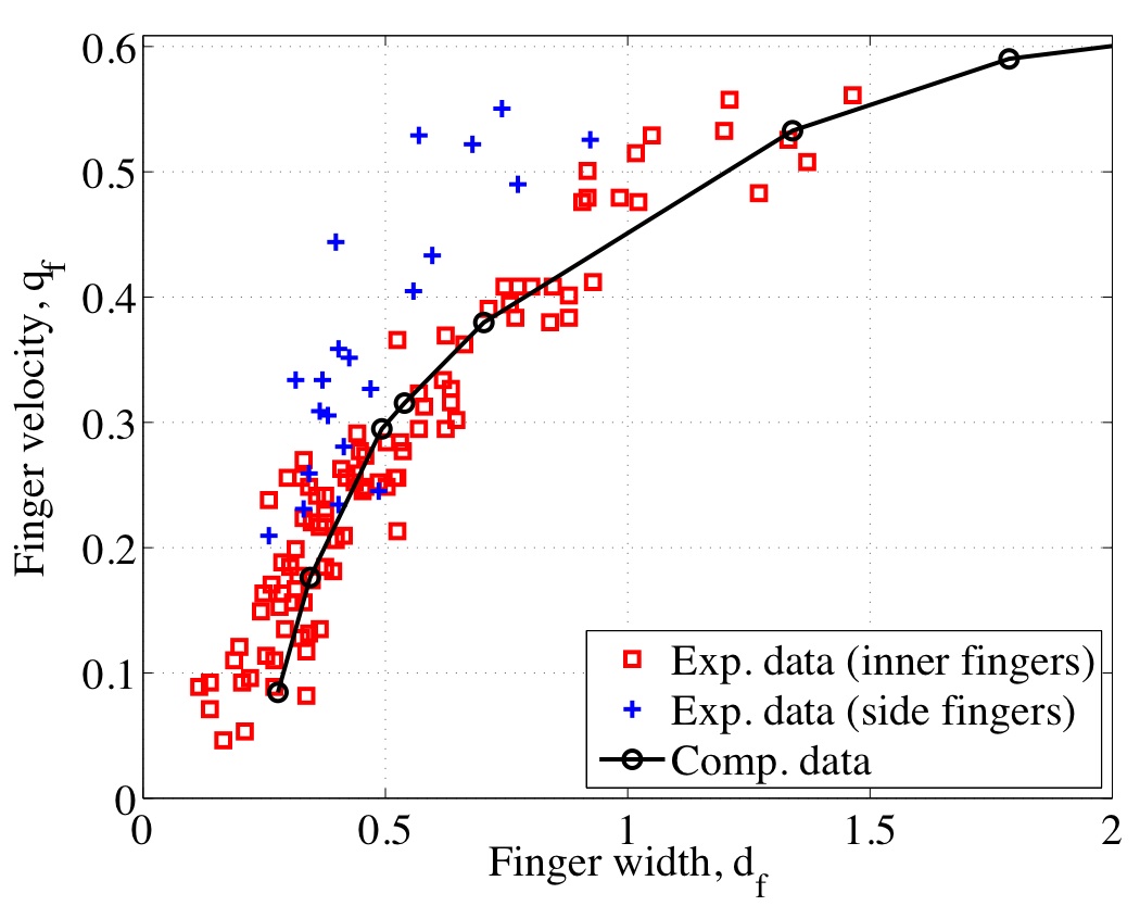
In Fig. 16, we present saturation contours from a series of simulations in which the infiltration flux is varied between 0.038 and 0.32 . Decreasing the causes an increase in the number of fingers, in addition to decreasing both finger velocity and tip saturation (as indicated in Fig. 15). The corresponding numerical values for various quantities are summarized in Table 4.
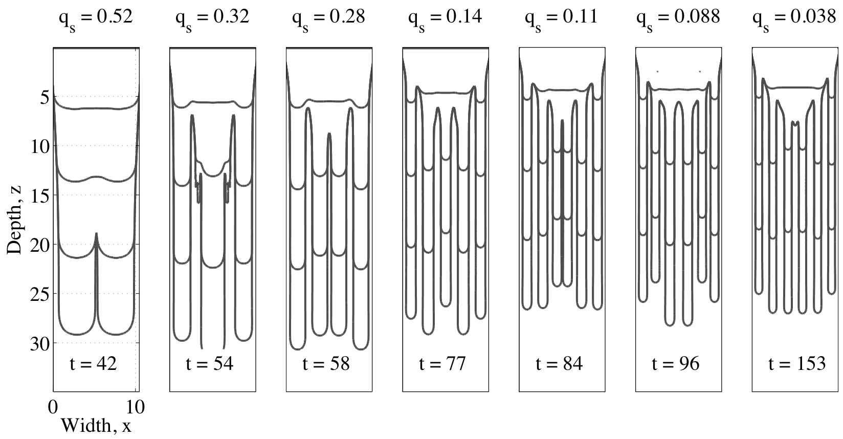
| Experimental data | Numerical simulations | |||||||
| 0.012 | 4 | 0.03 | 0.45 | 0.12 | 7 | 0.02 | 0.28 | 0.08 |
| 0.038 | 4 | 0.10 | 0.52 | 0.21 | 6 | 0.07 | 0.34 | 0.18 |
| 0.088 | 5 | 0.18 | 0.60 | 0.29 | 6 | 0.15 | 0.49 | 0.29 |
| 0.11 | 6 | 0.19 | 0.61 | 0.30 | 6 | 0.19 | 0.54 | 0.32 |
| 0.14 | 4 | 0.38 | 0.79 | 0.41 | 5 | 0.29 | 0.70 | 0.38 |
| 0.28 | 6 | 0.50 | 0.91 | 0.46 | 4 | 0.74 | 1.34 | 0.53 |
| 0.32 | 5 | 0.66 | 1.08 | 0.52 | 3 | 1.12 | 1.79 | 0.59 |
| 0.52 | – | – | – | – | 2 | 2.73 | 3.88 | 0.69 |
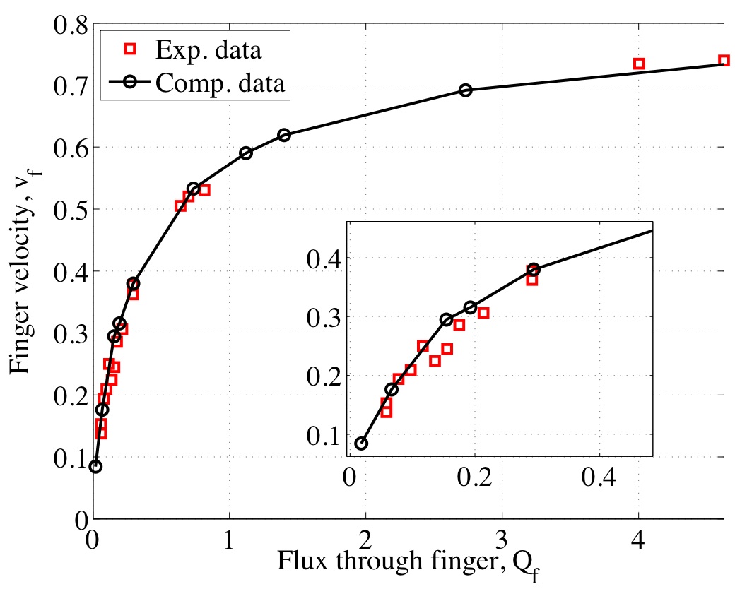
Following Glass et al. (1989a), we relate the average finger velocity () and width () to the average volume flow rate in a finger using . Since infiltration flux is related to finger velocity via , the finger volume flow rate can be written as
| (30) |
We then take our simulations for different values of and redisplay the results in Fig. 17 as a plot of finger velocity versus finger flow rate, including data from Glass et al.’s experiments. There is very close agreement between the simulated and experimental results. In particular, as the infiltration flux increases (or equivalently, increases) the slope of the velocity–flux curve decreases.
In Fig. 18, we present a plot of finger width versus flow rate in which the dependence is approximately linear. This behavior is consistent with Glass et al.’s experiments where they used a linear least squares fit to predict the finger width. However, the correlation here is not as strong and our computations significantly over-predict the finger width at higher values of finger flux.
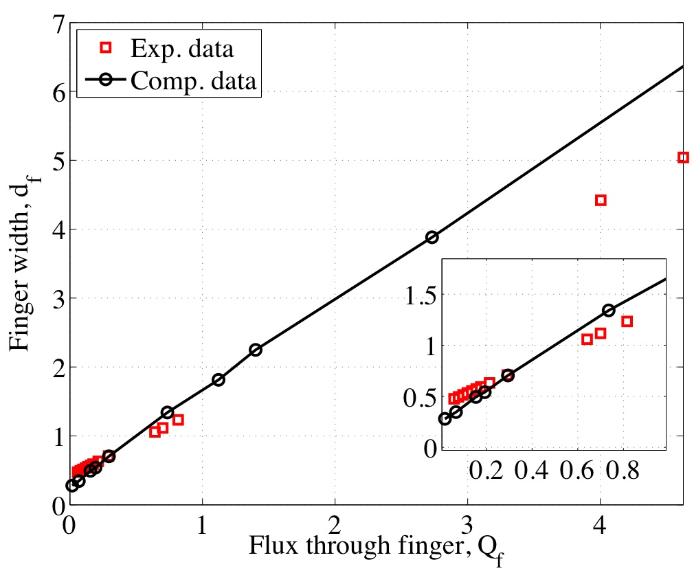
In an effort to explain this discrepancy, we plot finger velocity against finger width in Fig. 19, which includes the experimental data of Glass et al. (1989b). The experimental points are classified as corresponding to “side” and “inner” fingers (where side fingers lie immediately adjacent to the side boundaries) and significant differences are apparent between the two sets of fingers which Glass et al. attribute to boundary effects. If we focus only on the interior fingers, then our model does a very good job of capturing the observed behaviour. Indeed, it is the contribution of the side fingers to the average finger width that leads to the deviations in slope at higher flux in Fig. 18.
5 Discussion
In this study we investigated the ability of the RNERE model to capture gravity-driven fingering in unsaturated soils. Our results expand on previous studies of the RNERE model in two ways: first, by performing an extensive sensitivity analysis for various important physical parameters; and second, by drawing a systematic comparison between simulations and previously published experimental results. We showed that with a careful choice of initial saturation and capillary relaxation coefficient, the model is capable of accurately reproducing the fingering behaviour observed in experiments. Comparisons with several independent experimental studies attest to the accuracy and robustness of the RNERE approach.
In contrast to the work of DiCarlo (2005), who concluded that the RNERE does not contain all the required physics to describe gravity-driven fingering instabilities, we have shown that by coupling both non-equilibrium and hysteretic effects it is possible to capture fingering phenomena with the RNERE. Our numerical simulations demonstrate the importance of performing a detailed numerical convergence study in order to ensure that fingers have been sufficiently well resolved. The model sensitivity analysis showed that dynamic capillary terms must be properly handled if the fingered flow is to be captured accurately, and in particular that an accurate estimate of the parameter is essential. As more research is undertaken in the study of non-equilibrium capillary effects, we expect that more accurate and reliable experimentally-validated correlations for the capillary relaxation parameter will become available.
There are a number of possible avenues for future work that will be explored:
-
•
We will investigate the use of alternate iterative strategies that improve on the robustness and efficiency of the RNERE algorithm. We hope to draw inspiration in this respect from other well-known work on RE-based methods such as Celia et al. (1990) and Miller et al. (1998). Current advances in ODE solvers for dealing with event detection and non-smooth or discontinuous coefficients may also yield improvements in the treatment of hysteretic switching criteria, which has a big impact on convergence of the iterative scheme. Furthermore, there has been an explosion of recent work on alternate models for handling dynamic capillary effects which could be applied here (Beliaev and Schotting, 2001; Sander et al., 2008; Peszyńska and Yi, 2008; Helmig et al., 2007; Manthey et al., 2008).
-
•
Analytical results for fingered flow, derived using asymptotic or other approximate methods, will be studied to gain a better understanding of the impact of hysteresis and dynamic effects on the mechanics of finger formation. We will initially be guided by other previous work on traveling wave approximations for wetting fronts in the RNERE model with dynamic capillary effects (DiCarlo et al., 2008; Nieber et al., 2005) and hysteresis (Dautov et al., 2002; Sander et al., 2008).
-
•
Two alternate mathematical models have recently been proposed that are relevant to capturing gravity-driven fingering phenomena. The model of Cueto-Felgueroso and Juanes (2008) accounts for effective surface tension phenomena due to saturation gradients through the addition of a new fourth order derivative term in the equations. Their numerical results capture the main qualitative features of fingered flow without the need for hysteresis, although they state that hysteretic effects are still important and that hysteresis can be easily incorporated into their model (Cueto-Felgueroso and Juanes, 2009a). Another approach proposed by Pop et al. (2009) introduces an additional PDE for the interfacial area that obviates the need for an explicit treatment of hysteresis. We intend to perform an extensive computational comparison of these two models using a generalization of our RNERE approach, initially in 1D, that should help to elucidate the relative advantages and disadvantages of the various approaches.
Acknowledgements.
This work was funded by research grants from the Natural Sciences and Engineering Research Council of Canada and the MITACS Network of Centres of Excellence. JMS was supported by a Research Fellowship from the Alexander von Humboldt Foundation while visiting the Fraunhofer Institut Techno- und Wirtschaftsmathematik. We are sincerely grateful to the anonymous referees whose extensive and thoughtful comments led to significant improvements in this paper.References
- Barenblatt et al. (2003) Barenblatt, G. I., T. W. Patzek, and D. B. Silin (2003), The mathematical model of nonequilibrium effects in water-oil displacement, SPE J., 84, 409–416.
- Bauters et al. (2000) Bauters, T. W. J., D. A. DiCarlo, T. S. Steenhuis, and J.-Y. Parlange (2000), Soil water content dependent wetting front characteristics in sands, J. Hydrol., 231-232, 244–254.
- Belfort and Lehmann (2005) Belfort, B., and F. Lehmann (2005), Comparison of equivalent conductivities of numerical simulation of one dimensional unsaturated flow, Vadose Zone J., 4, 1191–1200.
- Beliaev and Schotting (2001) Beliaev, A. Y., and R. J. Schotting (2001), Analysis of a new model for unsaturated flow in porous media including hysteresis and dynamic effects, Comput. Geosci., 5, 345–368.
- Cardwell and Parsons (1945) Cardwell, W. T., and R. L. Parsons (1945), Average permeabilities of heterogeneous oil sands, Trans. AIME, 160, 34–42.
- Celia et al. (1990) Celia, M., E. Bouloutas, and R. Zarba (1990), A general mass-conservative numerical solution for the unsaturated flow equation, Water Resour. Res., 26(7), 1483–1496.
- Chuoke et al. (1959) Chuoke, R. L., P. van Meures, and C. van der Poel (1959), The instability of slow, immiscible, viscous liquid-liquid displacements in permeable media, Petroleum Trans. AIME, 216, 188–194.
- Cuesta and Hulshof (2003) Cuesta, C., and J. Hulshof (2003), A model problem for groundwater flow with dynamic capillary pressure: stability of travelling waves, Nonlin. Anal. Modelling Control, 52, 1199–1218.
- Cuesta et al. (2000) Cuesta, C., C. van Duijn, and J. Hulshof (2000), Infiltration in porous media with dynamic capillary pressure: Travelling waves, Euro. J. Appl. Math., 11, 381–397.
- Cuesta (2003) Cuesta, C. M. (2003), Pseudo-parabolic equations with driving convection term, Ph.D. thesis, Vrije Universiteit Amsterdam.
- Cuesta and Pop (2009) Cuesta, C. M., and I. S. Pop (2009), Numerical schemes for a pseudo-parabolic Burgers equation: Discontinuous data and long-time behaviour, J. Comput. Appl. Math., 224, 269–283.
- Cueto-Felgueroso and Juanes (2008) Cueto-Felgueroso, L., and R. Juanes (2008), Nonlocal interface dynamics and pattern formation in gravity-driven unsaturated flow through porous media, Phys. Rev. Lett., 101, 244504.
- Cueto-Felgueroso and Juanes (2009a) Cueto-Felgueroso, L., and R. Juanes (2009a), A phase field model of unsaturated flow, Water Resour. Res., 45, W10409.
- Cueto-Felgueroso and Juanes (2009b) Cueto-Felgueroso, L., and R. Juanes (2009b), Stability analysis of a phase-field model of gravity-driven unsaturated flow through porous media, Phys. Rev. E, 79, 036301.
- Das et al. (1994) Das, B., S. Steinberg, S. Weber, and S. Schaffer (1994), Finite difference methods for modelling porous media flows, Transp. Porous Media, 17, 171–200.
- Dautov et al. (2002) Dautov, R. Z., A. G. Egorov, J. L. Nieber, and A. Y. Sheshukov (2002), Simulation of two-dimensional gravity-driven unstable flow, in Proceedings of the XIVth International Conference on Computational Methods in Water Resources (CMWR XIV), edited by W. G. Gray and G. F. Pinder, vol. 1, pp. 9–16, Elsevier, Delft, The Netherlands.
- de Rooij (2000) de Rooij, G. H. (2000), Modeling fingered flow of water in soils owing to wetting front instability: A review, J. Hydrol., 231-232, 277–294.
- DiCarlo (2004) DiCarlo, D. (2004), Experimental measurement of saturation overshoot on infiltration, Water Resour. Res., 40, W04215.
- DiCarlo (2005) DiCarlo, D. (2005), Modeling observed saturation overshoot with continuum additions to standard unsaturated theory, Adv. Water Res., 28, 1021–1027.
- DiCarlo (2007) DiCarlo, D. A. (2007), Capillary pressure overshoot as a function of imbibition flux and initial water content, Water Resour. Res., 43, W08402.
- DiCarlo et al. (2008) DiCarlo, D. A., R. Juanes, T. LaForce, and T. P. Witelski (2008), Nonmonotonic traveling wave solutions of infiltration into porous media, Water Resour. Res., 44, W02406.
- Diment and Watson (1985) Diment, G. A., and K. K. Watson (1985), Stability analysis of water movement in unsaturated porous materials. 3. Experimental studies, Water Resour. Res., 21(7), 979–984.
- Egorov et al. (2003) Egorov, A., R. Dautov, J. Nieber, and A. Sheshukov (2003), Stability analysis of gravity-driven infiltration flow, Water Resour. Res., 39(9), 1266.
- Eliassi and Glass (2001) Eliassi, M., and R. Glass (2001), On the continuum-scale modelling of gravity-driven fingers in unsaturated porous media: The inadequacy of the Richards equation with standard monotonic constitutive relations and hysteretic equations of state, Water Resour. Res., 37, 2019–2035.
- Eliassi and Glass (2002) Eliassi, M., and R. Glass (2002), On the porous-continuum modeling of gravity-driven fingers in unsaturated materials: Extension of standard theory with a hold-back-pile-up effect, Water Resour. Res., 38(11), 1234.
- Eliassi and Glass (2003) Eliassi, M., and R. Glass (2003), On the porous continuum-scale modelling of gravity-driven fingers in unsaturated materials: Numerical solution of a hypodiffusive governing equation that incorporates a hold-back-pile-up effect, Water Resour. Res., 39(6), 1167.
- Glass et al. (1989a) Glass, R., J.-Y. Parlange, and T. Steenhuis (1989a), Wetting front instability: 1. Theoretical discussion and dimensional analysis, Water Resour. Res., 25(6), 1187–1194.
- Glass et al. (1989b) Glass, R., T. Steenhuis, and J.-Y. Parlange (1989b), Wetting front instability: 2. Experimental determination of relationships between system parameters and two dimensional unstable flow field behavior in initially dry porous media, Water Resour. Res., 25(6), 1195–1207.
- Glass et al. (1990) Glass, R., S. Cann, J. King, N. Bailey, J.-Y. Parlange, and T. Steenhuis (1990), Wetting front instability in unsaturated porous media: A three-dimensional study in initially dry sand, Transp. Porous Media, 5, 247–268.
- Gutjahr et al. (1978) Gutjahr, A. L., L. W. Gelhar, A. A. Bakr, and J. R. MacMillan (1978), Stochastic analysis of spatial variability in subsurface flows. 2. Evaluation and application, Water Resour. Res., 14(5), 953–959.
- Hassanizadeh and Gray (1993) Hassanizadeh, S., and W. Gray (1993), Toward an improved description of the physics of two-phase flow, Adv. Water Res., 16, 53–67.
- Hassanizadeh et al. (2002) Hassanizadeh, S., M. Celia, and H. Dahle (2002), Dynamic effect in the capillary pressure-saturation relationship and its impact on unsaturated flow, Vadose Zone J., 1, 38–57.
- Haverkamp and Vauclin (1979) Haverkamp, R., and M. Vauclin (1979), A note on estimating finite difference interblock hydraulic conductivity values for transient unsaturated flow problems, Water Resour. Res., 15(1), 181–187.
- Helmig et al. (2007) Helmig, R., A. Weiss, and B. Wohlmuth (2007), Dynamic capillary effects in heterogeneous porous media, Comput. Geosci., 11, 261–274.
- Hill and Parlange (1972) Hill, D. E., and J.-Y. Parlange (1972), Wetting front instability in layered soils, Soil Sci. Soc. Amer. Proc., 36(5), 697–702.
- Hornung and Messing (1983) Hornung, U., and W. Messing (1983), Truncation errors in the numerical solution of horizontal diffusion in saturated/unsaturated media, Adv. Water Res., 6(3), 165–168.
- Juanes (2008) Juanes, R. (2008), Nonequilibrium effects in models of three-phase flow in porous media, Adv. Water Res., 31, 661–673.
- King and Cuesta (2006) King, J. R., and C. M. Cuesta (2006), Small- and waiting-time behavior of a Darcy flow model with a dynamic pressure saturation relation, SIAM J. Appl. Math., 66(5), 1482–1511.
- Lu et al. (1994) Lu, T. X., J. W. Biggar, and D. R. Nielsen (1994), Water movement in glass bead porous media. 2. Experiments of infiltration and finger flow, Water Resour. Res., 30(12), 3283–3290.
- Manthey et al. (2008) Manthey, S., S. M. Hassanizadeh, R. Helmig, and R. Hilfer (2008), Dimensional analysis of two phase flow including a rate-depedent capillary pressure-saturation relationship, Adv. Water Res., 31, 1137–1150.
- Miller et al. (1998) Miller, C. T., G. A. Williams, C. T. Kelley, and M. D. Tocci (1998), Robust solution of Richards’ equation for non-uniform porous media, Water Resour. Res., 34(10), 2599–2610.
- Mitkov et al. (1998) Mitkov, I., D. M. Tartakovsky, and C. L. Winter (1998), Dynamics of wetting fronts in porous media, Phys. Rev. E, 58, R5245–R5248.
- Nieber (1996) Nieber, J. (1996), Modeling finger development and persistence in initially dry porous media, Geoderma, 70, 207–229.
- Nieber et al. (2003) Nieber, J., A. Sheshukov, A. Egorov, and R. Dautov (2003), Non-equilibrium model for gravity-driven fingering in water repellent soils: Formulation and 2D simulations, in Soil Water Repellency: Occurrence, Consequences, and Amelioration, edited by C. J. Ritsema and L. W. Dekker, chap. 23, pp. 245–257, Elsevier, Wageningen, The Netherlands.
- Nieber et al. (2005) Nieber, J., R. Dautov, A. Egorov, and A. Sheshukov (2005), Dynamic capillary pressure mechanism for instability in gravity-driven flows: Review and extension to very dry conditions, Transp. Porous Media, 58, 147–172.
- Nieber et al. (2000) Nieber, J. L., T. W. J. Bauters, T. S. Steenhuis, and J.-Y. Parlange (2000), Numerical simulation of experimental gravity-driven unstable flow in water repellent sand, J. Hydrol., 231-232, 295–307.
- Parlange and Hill (1976) Parlange, J.-Y., and D. Hill (1976), Theoretical analysis of wetting front instability in soils, Soil Sci., 122(4), 236–239.
- Peszyńska and Yi (2008) Peszyńska, M., and S.-Y. Yi (2008), Numerical methods for unsaturated flow with dynamic capillary pressure in heterogeneous porous media, Int. J. Numer. Anal. Model., 5(Suppl.), 126–149.
- Philip (1975) Philip, J. (1975), Stability analysis of infiltration, Soil Sci. Soc. Amer. Proc., 39, 1049–1053.
- Pinales et al. (2005) Pinales, A., A. Chavez, G. Llerar, L. Manzanares, and A. Keer (2005), An improved approach for assigning pumping rates to heterogeneous aquifer models, Ground Water, 43(2), 274–279.
- Pop (2002) Pop, I. S. (2002), Error estimates for a time discretization method for the Richards’ equation, Comput. Geosci., 6, 141–160.
- Pop et al. (2009) Pop, I. S., C. J. van Duijn, J. Niessner, and S. M. Hassanizadeh (2009), Horizontal redistribution of fluids in a porous medium: The role of interfacial area in modeling hysteresis, Adv. Water Res., 32(3), 383–390.
- Raats (1973) Raats, P. (1973), Unstable wetting fronts in uniform and nonuniform soils, Soil Sci. Soc. Amer. Proc., 37, 681–684.
- Saffman and Taylor (1958) Saffman, P., and G. Taylor (1958), The penetration of a fluid into a porous medium or Hele-Shaw cell containing a more viscous liquid, Proc. Roy. Soc. Lond. A, 245(1242), 312–329.
- Sander et al. (2008) Sander, G. C., O. J. Glidewell, and J. Norbury (2008), Dynamic capillary pressure, hysteresis and gravity-driven fingering in porous media, J. Phys. Conf. Ser., 138, 012023.
- Schroth et al. (1996) Schroth, M. H., S. J. Ahearn, J. S. Selker, and J. D. Istok (1996), Characterization of Miller-similar silica sands for laboratory hydrologic studies, Soil Sci. Soc. Amer. J., 60, 1331–1339.
- Scott et al. (1983) Scott, P., G. Farquhar, and N. Kouwen (1983), Hysteretic effects on net infiltration, in Advances in Infiltration, vol. 11-83, pp. 163–170, American Society of Agricultural Engineers, St. Joseph, MI.
- Selker et al. (1992a) Selker, J., P. Leclerq, J.-Y. Parlange, and T. Steenhuis (1992a), Fingered flow in two dimensions. 1. Measurement of matric potential, Water Resour. Res., 28(9), 2513–2521.
- Selker et al. (1992b) Selker, J., J.-Y. Parlange, and T. Steenhuis (1992b), Fingered flow in two dimensions. 2. Predicting finger moisture profile, Water Resour. Res., 28(9), 2523–2528.
- Starke (2000) Starke, G. (2000), Least-squares mixed finite element solution of variably saturated subsurface flow problems, SIAM J. Sci. Comput., 21(5), 1869–1885.
- Stauffer (1978) Stauffer, F. (1978), Time dependence of the relations between capillary pressure, water content and conductivity during drainage of porous media, in Proceedings of the International Association of Hydraulic Engineering and Research, pp. 3.35–3.52, Thessaloniki, Greece.
- van Dam and Feddes (2000) van Dam, J. C., and R. A. Feddes (2000), Numerical simulation of infiltration, evaporation and shallow groundwater levels with the Richards equation, J. Hydrol., 233, 72–85.
- van Duijn et al. (2004) van Duijn, C., G. Pieters, and P. Raats (2004), Steady flows in unsaturated soils are stable, Transp. Porous Media, 57, 215–244.
- van Duijn et al. (2007) van Duijn, C. J., L. A. Peletier, and I. S. Pop (2007), A new class of entropy solutions of the Buckley–Leverett equation, SIAM J. Math. Anal., 39(2), 507–536.
- van Genuchten (1980) van Genuchten, M. (1980), A closed form equation for predicting the hydraulic conductivity of unsaturated soils, Soil Sci. Soc. Amer. J., 44, 892–898.
- Wang et al. (1998) Wang, Z., J. Feyen, and D. Elrick (1998), Prediction of fingering in porous media, Water Resour. Res., 34(9), 2183–2190.
- Wang et al. (2003) Wang, Z., A. Tuli, and W. Jury (2003), Unstable flow during redistribution in homogeneous soil, Vadose Zone J., 2, 52–60.
- Wang et al. (2004) Wang, Z., W. A. Jury, A. Tuli, and D.-J. Kim (2004), Unstable flow during redistribution: Controlling factors and practical implications, Vadose Zone J., 3, 549–559.
- Warren and Price (1961) Warren, J. E., and H. S. Price (1961), Flow in heterogeneous porous media, SPE J., 1, 153–167.
- Warrick (1991) Warrick, A. W. (1991), Numerical approximations of Darcian flow through unsaturated soil, Water Resour. Res., 27(6), 1215–1222.
- Yao and Hendrickx (2001) Yao, T., and J. M. H. Hendrickx (2001), Stability analysis of the unsaturated water flow equation. 2. Experimental verification, Water Resour. Res., 37(7), 1875–1881.
- Zaidel and Russo (1992) Zaidel, J., and D. Russo (1992), Estimation of finite difference interblock conductivities for simulation of infiltration into dry soil, Water Resour. Res., 28(9), 2285–2295.