The number of beams in IMRT - theoretical investigations and implications for single-arc IMRT
Abstract
The first purpose of this paper is to shed some new light on the old question of selecting the number of beams in intensity-modulated radiation therapy (IMRT). The second purpose is to illuminate the related issue of discrete static beam angles vs. rotational techniques, which has recently re-surfaced due to the advancement of volumetric arc therapy (VMAT). A specific objective is to find analytical expressions that allow one to address the points raised above. To make the problem mathematically tractable, it is assumed that the depth dose is flat and that the lateral dose profile can be approximated by polynomials, specifically Chebyshev polynomials of the first kind, of finite degree. The application of methods known from image reconstruction then allows one to answer the first question above as follows: The required number of beams is determined by the maximum degree of the polynomials used in the approximation of the beam profiles, which is a measure of the dose variability. There is nothing to be gained by using more beams. In realistic cases, in which the variability of the lateral dose profile is restricted in several ways, the required number of beams is of the order of 10 to 20. The consequence of delivering the beams with a ‘leaf sweep’ technique during continuous rotation of the gantry, as in VMAT, is also derived in analytical form. The main effect is that the beams fan out, but the effect near the axis of rotation is small. This result can serve as a theoretical justification of VMAT. Overall the analytical derivations in this paper, albeit based on strong simplifications, provide new insights into, and a deeper understanding of, the beam angle problem in IMRT. The decomposition of the beam profiles into well-behaved and easily deliverable smooth functions, such as Chebyshev polynomials, could be of general interest in IMRT treatment planning.
Keywords: IMRT, number of beams, Chebyshev polynomial, single-arc, VMAT
1 Introduction
The problem of selecting the number and direction of beams in intensity-modulated radiation therapy (IMRT) has been investigated by many and has been the subject of debate as early as in 1995 [Mohan1995]. One may argue that even today, after many more papers have been published on this topic, the results are not entirely convincing, and not practically useful overall. In fact, in today’s clinical practice, the number and direction of beams often has to be found by trial and error. Two ‘schools’ of IMRT delivery co-exist today: in the more common approach, a relatively small number (typically of the order of 10 or less) of fixed intensity-modulated beams is delivered with a multileaf collimator (MLC). In another approach, a very large number () of beams is used in the rotational tomotherapy approach [Mackie1993, Carol1994]. More recently, another rotational IMRT approach, ‘Single-Arc’, has been developed [Cameron2005, Ulrich2007, Otto2008, Wang2008] and has found a lot of interest as a commercial product (RapidArc, VMAT). In the Single-Arc approach there is no intensity modulation for any one beam angle, but the radiation field shape is varied dynamically and rapidly with an MLC as the gantry rotates around the patient. In the rotational approaches, the selection of beam angles is not a problem, but the distribution of dose over large volumes of healthy tissues has been a concern.
Intuitively one would expect that using more beams will always help to shape radiation dose distributions to match the tumor target volume, even though it is clear that there is a point of diminishing return. In this paper I will address the ‘how many beams’ problem from a theoretical viewpoint. I will introduce strong simplifications to make the problem mathematically tractable. The mathematical approach used here is similar to the one from an earlier paper on image reconstruction [Bortfeld1999]. One of the results is that, contrary to the intuition, there is no benefit whatsoever in increasing the number of beams beyond a certain threshold, which depends on the achievable amount of intensity modulation per beam. I will present some illustrative examples.
In the last methodological chapter I will take the step from standard IMRT with a small number () of fixed beam angles towards rotational therapy. From what I said above it is clear that dynamically rotating the beam cannot yield better dose distributions, but it can potentially reduce the treatment time. First I will derive a simple equation to describe the effect of rotating the gantry while IMRT is being delivered with a sweep technique [Convery1992]. I will apply this equation to the delivery of polynomial beam profiles over short arcs of . As a result, the impact of this small angle rotation is small, thus serving as a theoretical justification of the Single-Arc approach.
2 Polynomial approximations
Let us adopt the coordinate system from an earlier paper [Bortfeld1999]. Here the -axis points from left to right, and the axis points to the radiation source at the gantry position. In other words, at gantry angle, the beam goes in the direction, i.e., downwards. The gantry angle is counted positive in the counter-clockwise direction; note, however, that the gantry angle was defined in reversed (i.e., in clockwise) orientation in a more recent paper [Bortfeld2009].
I will use a zero-order approximation of the depth dose distribution, i.e., I assume that the depth-dose is flat. This means in particular that I ignore beam divergence and the variability of scatter as a function of depth. Incidentally, one can consider this approximation as a first order approximation (linear depth-dose profile) if one uses parallel-opposed beams, but parallel-opposed beams will not be considered further in the rest of this paper. Within this approximation one can now write the two-dimensional dose resulting from a beam impinging under an angle with fluence (intensity) profile as
| (1) |
Here and is the unit vector perpendicular to the beam direction. In image reconstruction terminology, equation (1) is a ‘backprojection’, i.e., a ‘smearing out’ of fluence values along the rays of the beam [Bortfeld1999]. In section 7 I will discuss why I believe that, in spite of this strong simplification, the results are not only of theoretical but also of some practical relevance.
Let us now make one additional assumption, namely that one can write the fluence (intensity) profiles as a set of polynomials of degree . This should always be possible because in practice the fluence profile is well behaved thanks to the finite source size, scatter, partial transmission through the leaf ends of the MLC, among other reasons.
Under these assumptions, it follows from an earlier paper [Bortfeld1999] that one can produce any dose distribution of the form
| (2) |
within the unit circle using evenly spaced beams. Here are arbitrary weight factors. Equation (2) can be considered as a special form of a polynomial approximation of an arbitrary two-dimensional dose distribution . A perhaps more important result of that paper is that the required number of beams equals , the maximum degree polynomial plus 1. In particular, there is no benefit at all in using more than beams. For a better understanding of these finding I will consider a specific set of polynomials, Chebyshev polynomials.
2.1 Chebyshev polynomials of the first kind
Chebyshev polynomials of the first kind, are a special set of (orthogonal) polynomials that can also be defined using cosine functions, namely:
| (3) |
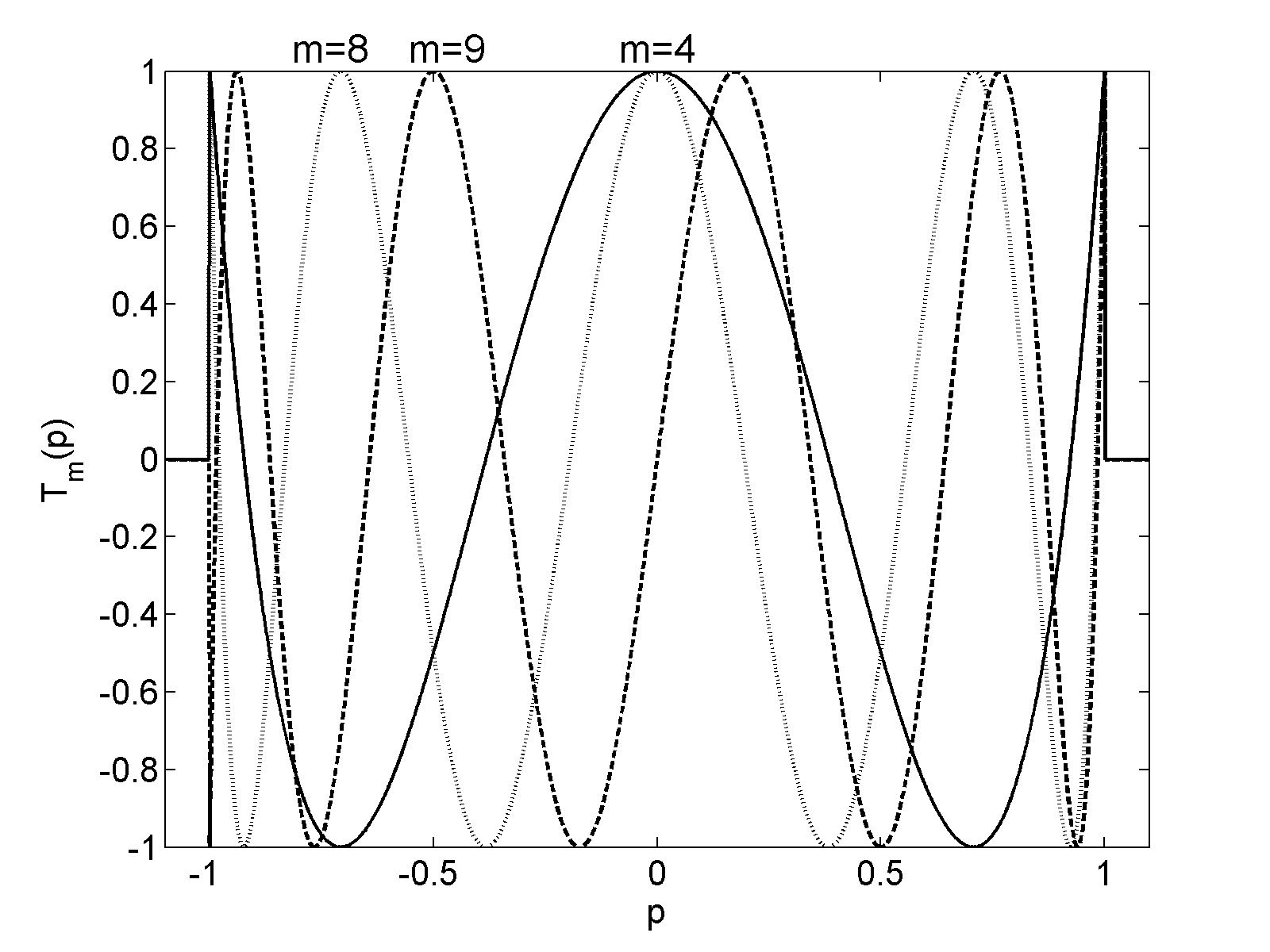
They are defined on the interval and can be considered as cosine or sine functions for even and odd , respectively, with a frequency that increases away from the origin. On the other hand, they are also polynomials, for example , and . Figure 1 shows those Chebyshev polynomials , , and .
In an earlier paper [Bortfeld1999] some properties of Chebyshev polynomials of the second kind, , were utilized. Those Chebyshev polynomials of the second kind are Eigenfunctions of the operation consisting of a backprojection and subsequent projection under a different angle. The two kinds of Chebyshev polynomials are related through the following equation:
| (4) |
Here I will focus on Chebyshev polynomials of the first kind because they oscillate between and , and issues with negativity [Cormack1989] can therefore be avoided simply by a zero-offset of . Chebyshev polynomials have been used in the theory of IMRT by Cormack et al. [Cormack1987, Cormack1987a, Cormack1989] but, to the best of my knowledge, they have not been used to get a handle on the beam angle problem.
3 ‘Making’ rotating beams from fixed beam angles
The fact that one does not need more than beams if each of the beam fluence profiles can be described by a polynomial of degree up to , will now be illustrated using the polynomial (the solid line in figure 1) as an example. If one uses fixed beams evenly spaced at angles , where , and each of those 5 beams delivers a fluence profile of variable weight, then one can ‘make’ a beam with a fluence profile from an arbitrary angle . The weights of the fixed beams to be used are given by
| (5) |
with and in this case. This result follows from appendix A in [Bortfeld1999], in which has to be replaced with , and then from equation (4). If , then , and the sign can be determined with l’Hôpital’s rule.
Figure 2 illustrates these findings graphically for , , and . The weights calculated with equation (5) are attached to the 5 beams in the plots. In figure 2a with the beam in vertical direction (), only the vertical fixed beam () has a weight of 1, and the four others a weight of 0. In figures 2b and 2c all five beams contribute with a finite weight to ‘make’ those oblique beam directions.
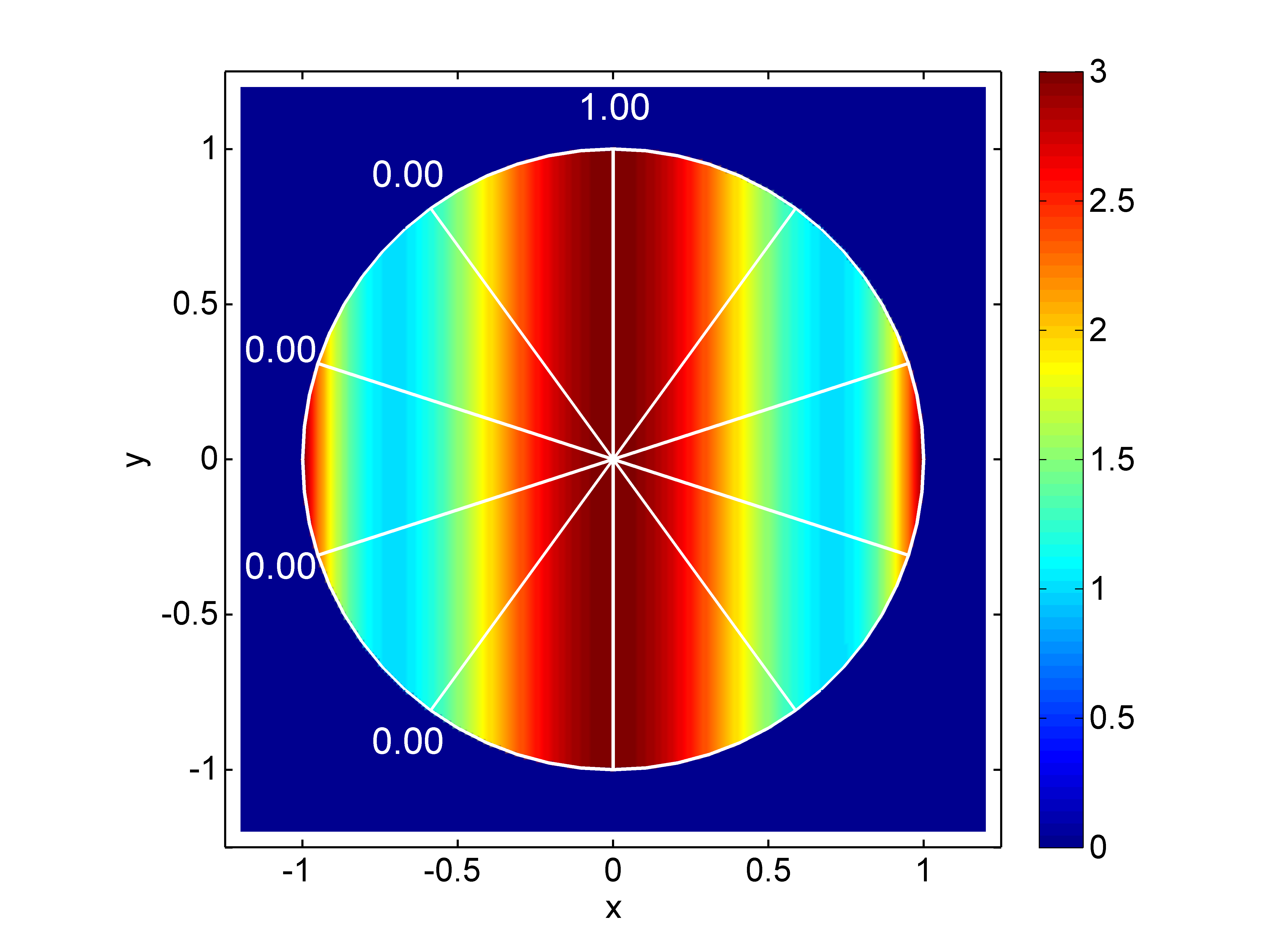
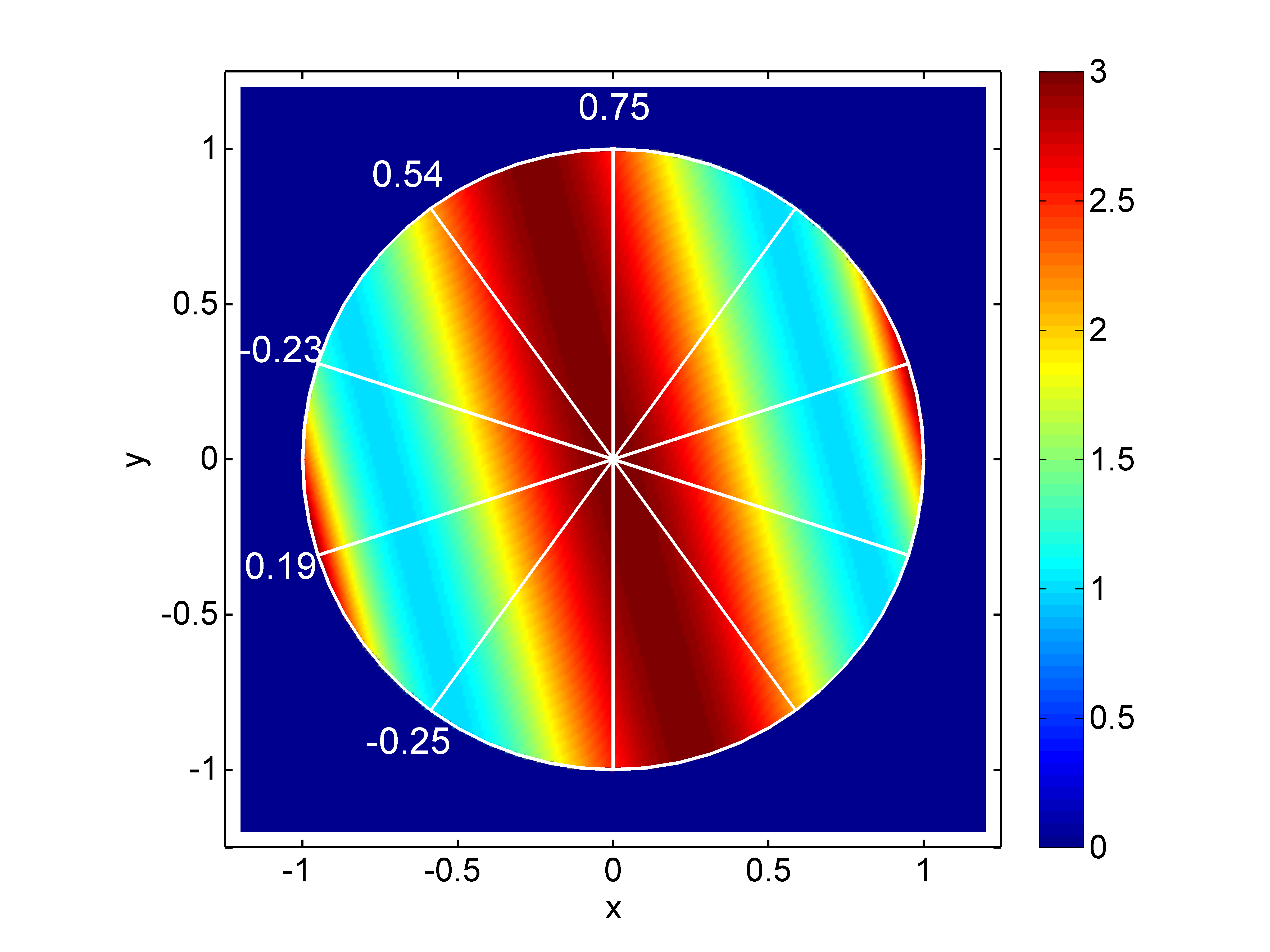
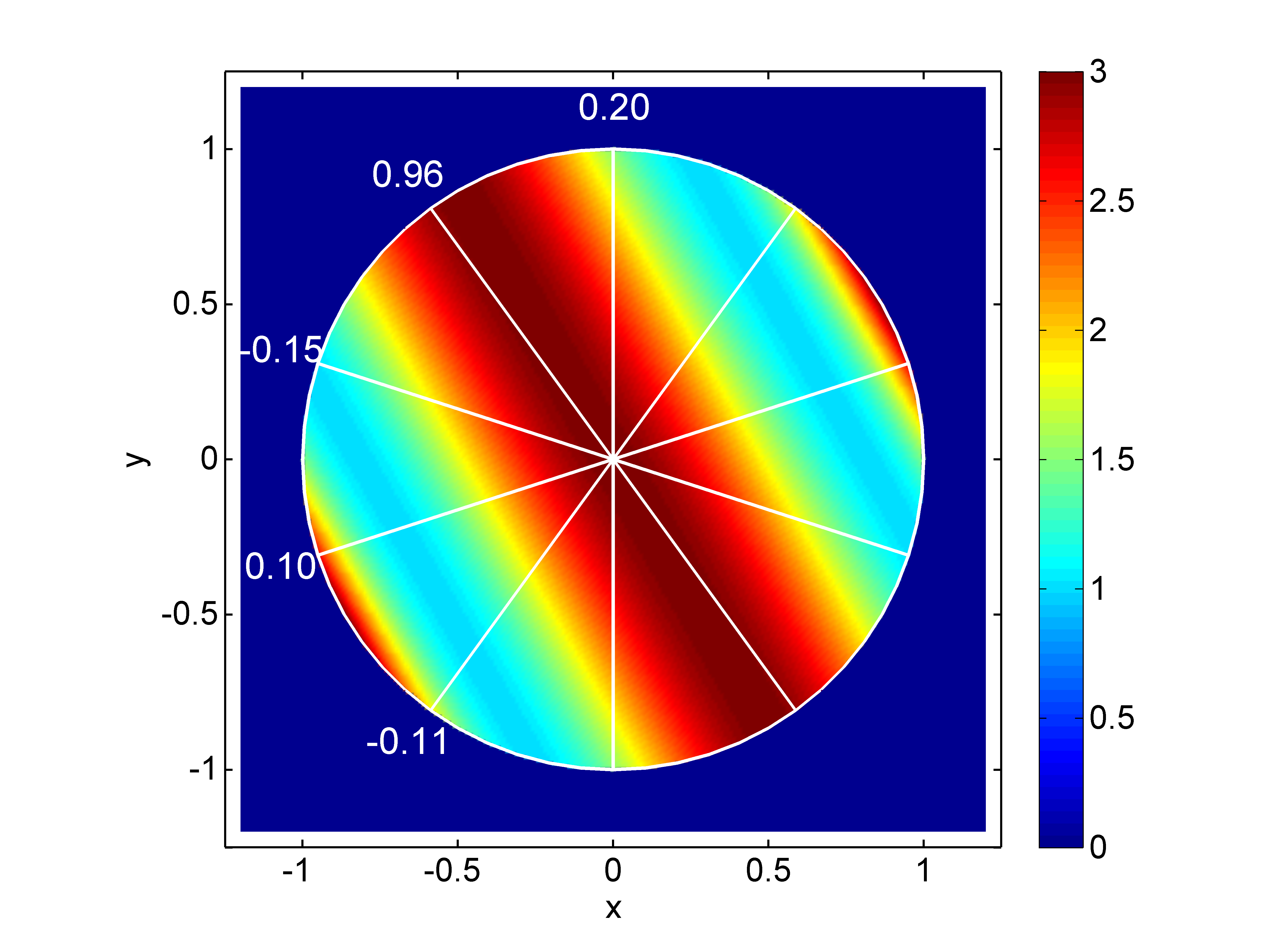
For each of the beams, a zero-offset (i.e., a uniform fluence profile) has to be added to make the fluence non-negative. The total zero-offset over all beams depends on the weights , as calculated using equation (5), and therefore on . The biggest total zero-offset is required for , and is close to 2. I therefore use a total zero-offset of 2 in all cases shown in figure 2. I should mention that a dose profile with arbitrary orientation can also be generated from 5 fixed beams with intensity profiles that are polynomials of degree 4 but not Chebyshev profiles. In other words, there is a ‘nullspace’ that leads to non-uniqueness [Cormack1987]. However, one can show numerically that the use of 5 profiles (evenly spaced) requires the smallest zero-offset.
Moreover, it is interesting to note that beams with arbitrary orientation can also be generated from a number of fixed beams that are not evenly spaced but arbitrarily located. This finding may serve as an explanation that the choice of beam angles is generally less critical in IMRT than in standard 3D conformal radiation therapy without intensity modulation. However, with non-equally spaced beams, the solutions (the equivalent of equation (5)) may become highly oscillatory (i.e., one beam may require a large positive weight and the next a large negative weight), and very large zero-offsets may be required.
4 A simple two-dimensional example
For a further illustration of the findings from above, let us now look at a simple 2-D IMRT example case: a circular target volume that ‘wraps around’ a circular critical structure. To match the region of support of the Chebyshev polynomials, the radius of the target is set to 1 unit, with its center positioned at . The critical structure has a radius of 1/3 units and its center is at . This geometry corresponds with the geometry used in a recent paper [Bortfeld2009]. The dose prescription has a dose level of 1 unit to the target volume, and a reduction to 0.5 units in the critical structure. The 50% dose reduction in the critical structure is chosen as a challenging but realistic value, and to avoid any issues with negativity.
The calculation of the IMRT fluence profiles is done with the recipe from an earlier paper, see page 1109 in [Bortfeld1999]. Here I approximate the fluence profiles with Chebyshev polynomials with degrees between and , see figure 1. The specific steps of the calculation are:
-
1.
Projection of the prescribed dose along evenly spaced beam directions with angles at lateral positions .
-
2.
Discrete sine transform of each of those projections.
-
3.
Multiplication of the coefficients with a ‘ramp filter’.
-
4.
Composition of ‘filtered projections’ to obtain the fluence profiles.
The last step above involves the use of Chebyshev polynomials of the second kind. For consistency with the rest of this paper, the algorithm can be re-written for the use of Chebyshev polynomials of the first kind through equation (4).
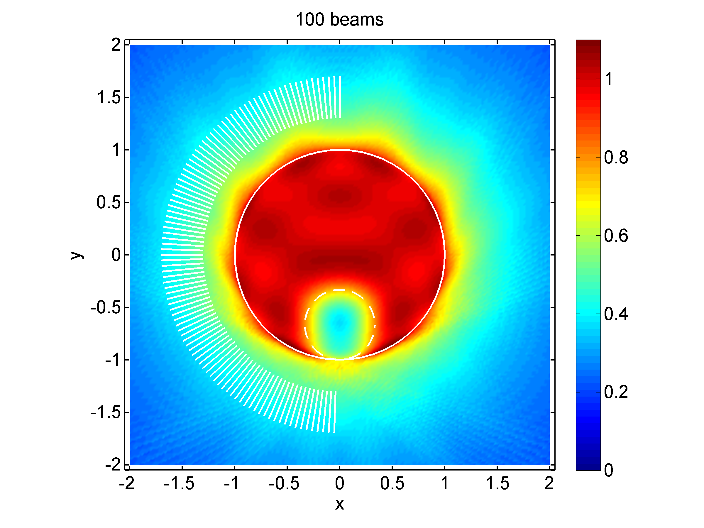
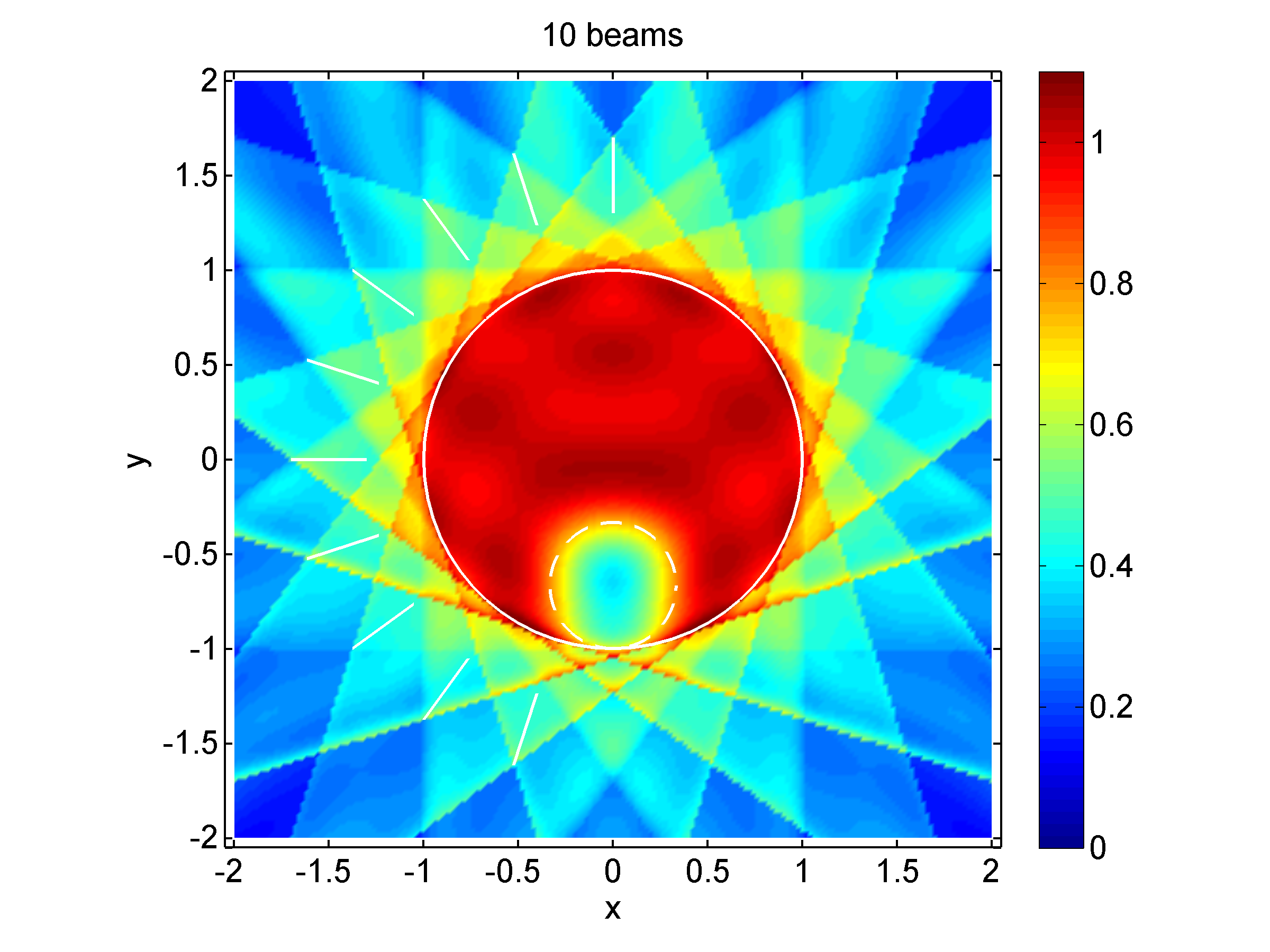
After the calculation of the fluence profiles, those profiles are then backprojected, which simulates an irradiation with beams. Figure 3(a) shows the resulting dose distribution for beams that are evenly spaced at every . Now, as I said above, for polynomial fluence profiles of degree up to , beam angles should actually suffice. To illustrate this point, I use beams at every in figure 3b. The 10 fluence profiles are calculated from the case with 100 beams by use of equation (5). I should note that after the re-distribution into the 10 fluence profiles, there is no guarantee that all of them are non-negative, even if the original 100 profiles are all non-negative. However, in this specific case negativity is not an issue. By comparing figures 3(a) and 3(b) one can now see that the two dose distribution are indeed identical within the unit circle, which encompasses the target volume and the critical structure. Only outside of the unit circle the two distributions begin to differ more and more: with beams the distribution is more uniform, whereas the case with beams exhibits the typical ragged distribution. With fewer than beams, there would be differences also within the unit circle.
5 How many beams are needed?
Can one now find a general answer to this question? As I said above, the variability of the fluence profiles, measured by the degree of the Chebyshev polynomials approximating those fluence profiles, determines how many beam are needed. The fluence variability depends, in turn, on the complexity of the dose prescription, and is therefore case dependent. However, even the most complex cases do not benefit from an arbitrarily high number of beams. This is so because there is also a physical limit on the achievable amount of fluence (or rather dose) modulation, which is due to the reasons mentioned above (scatter, transmission, finite source size). This physical limit reveals itself through the fact that the dose fall-off at a field edge is never infinitely steep, but exhibits a dose ‘penumbra’. Specifically, the width of the penumbra (80% to 20%) near the leaf-end of an MLC at a typical treatment depth is of the order of 7 mm [Boyer1992]. As a consequence, the minimum width (full width at half maximum, FWHM) of a deliverable dose peak, , is of the order of [Bortfeld2000]. Now, by interpreting Chebyshev fluence profiles as a series of dose peaks (see figure 1), one can correlate this physical limit with the maximum degree polynomial that can be delivered, and thus with the required number of beams.
Chebyshev polynomials of the first kind have roots. The roots cut the interval into sub-intervals, which represent the peaks and valleys of . The average width of the sub-intervals is , hence the average peak width is also (FWHM). To give this expression a quantitative meaning, one has to identify the 2 units in the numerator with , where is the radius of the the circular region of interest, which was set to 1 in the abstract examples above. The region of interest contains the target volume and the most important nearby critical structures, which may extend into the target volume. Thus the average peak width is . If one equates this with the physical limit, above, and utilizes the fact that governs the required number of beams, , one obtains:
| (6) |
To give a couple of examples, for relatively small cases where the radius of the region of interest is , beams are required, whereas for larger cases with , one needs beams. For ‘sharper’ beams with smaller penumbra, i.e., with a smaller , the number is correspondingly higher.
6 Towards a theoretical justification of Single-Arc
Now that it has been shown that a finite and moderate number, , of fixed IMRT beams suffices, how can one justify Single-Arc IMRT (RapidArc, VMAT), in which the number of beams is effectively infinite, but without intensity modulation from any one beam direction? One way to provide a theoretical foundation of Single-Arc is as follows: Let us start with beams and assume that the fluence profile for each beam is delivered with a ‘sweep’ technique [Convery1992], see A, in which the leaves move uni-directionally, say from left to right. What is the impact on the fluence and dose distribution, if one delivers the dose from each beam not while the gantry is static at a fixed beam angle, but rotating over the angle ? Some investigations to answer this question were presented in [Webb2009]. A closed form answer is derived in A. Basically the impact of gantry motion during leaf sweep IMRT delivery is a stretching or compression of the fluence profile111This effect is quite different in the case of beam modulator (‘compensator’) based IMRT and tomotherapy, in which gantry motion leads to a ‘smearing’ of the fluence distribution., depending on whether the gantry motion increases (prograde motion) or decreases (retrograde motion) the motion of the field edges (the projected leaf ends).
For leaf sweep IMRT, the fluence profiles are typically decomposed into two components and , which represent the positive and negative slopes in , respectively, and for which . Now let and be the respective fluence profiles that result when there is gantry motion during delivery. In the case of prograde motion, where the effective leaf speed is increased by a positive value , it is shown in A.1 that for any point
| (7) |
where is an arbitrary constant shift, which could be zero. This means that the profile has the same values as the profile, but it is stretched in the direction of . For retrograde motion, where is negative, the corresponding equation (28) is derived in A.2 and looks a little more complicated because leaves can move backwards in this case. However, because the stretching or compression is generally different for and , the impact on can be more substantial.
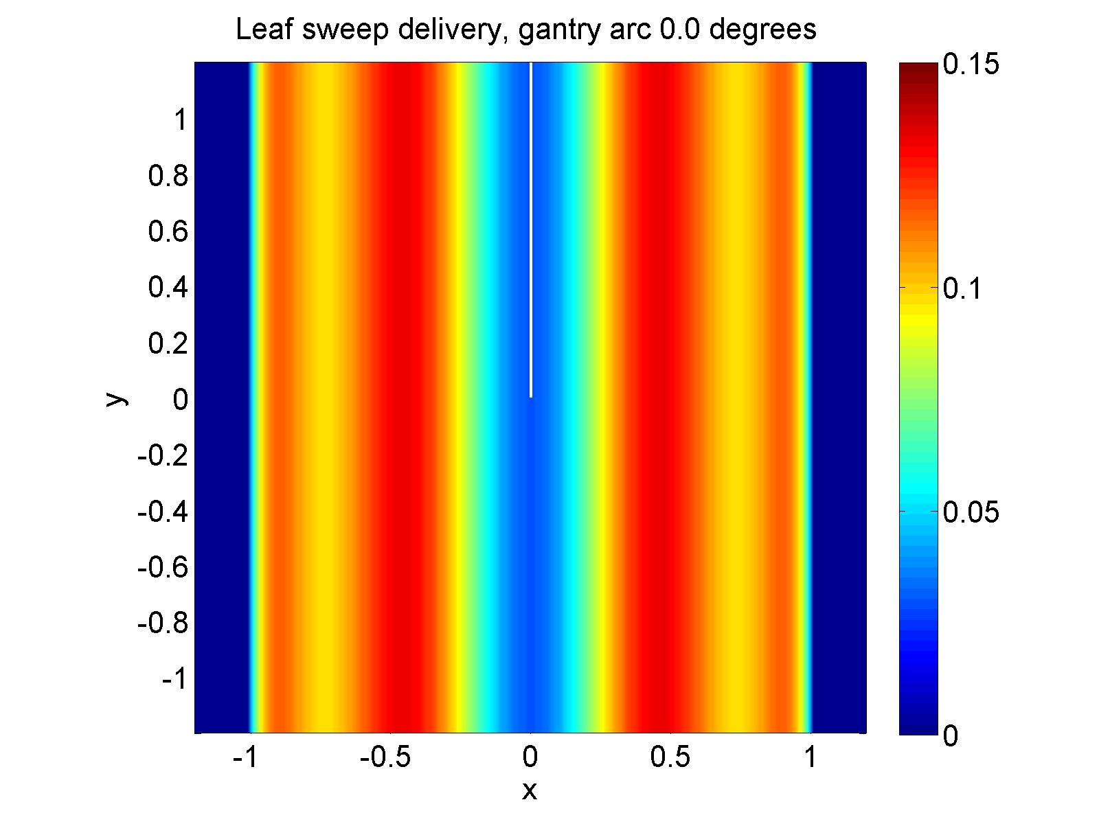
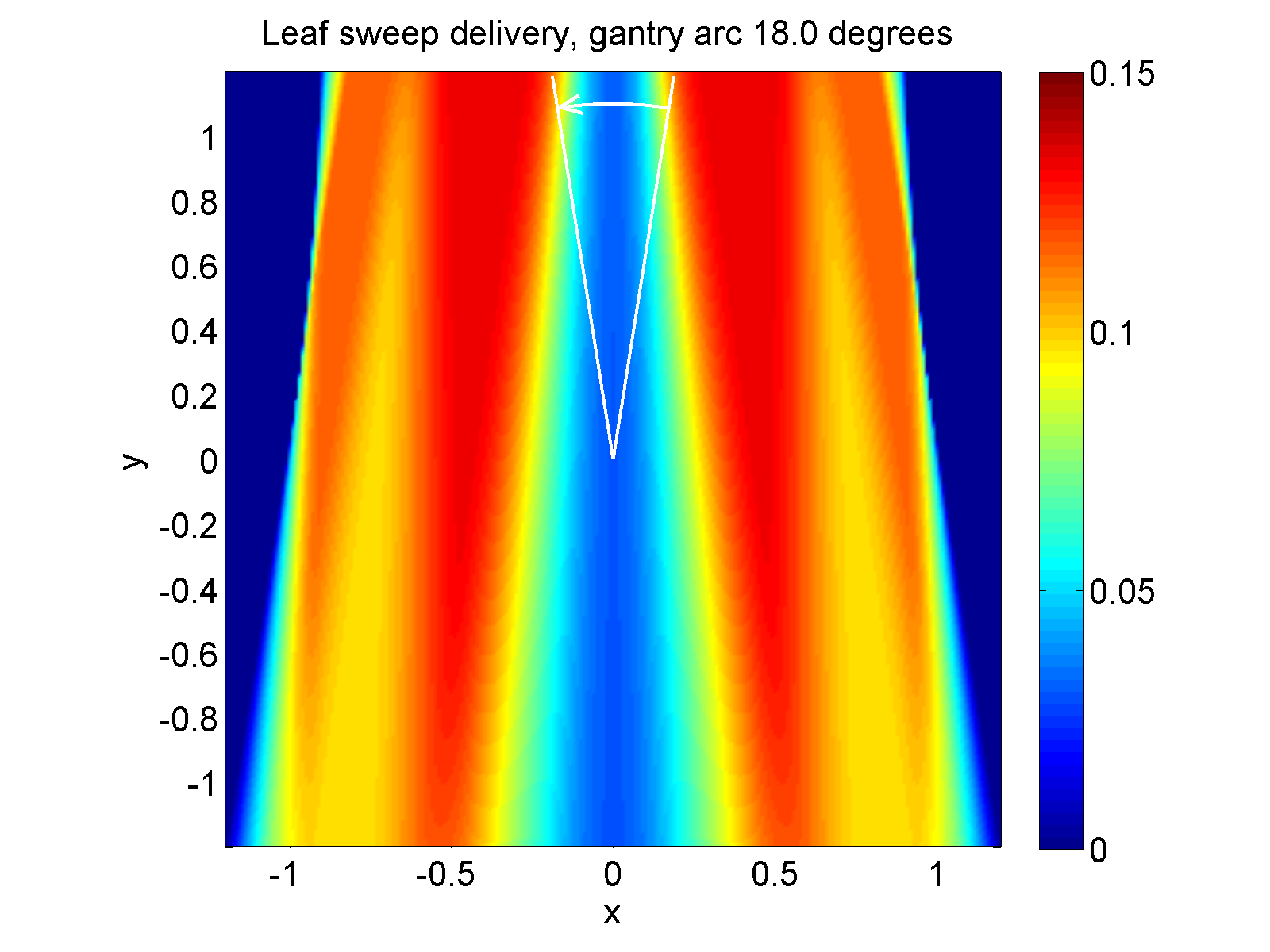
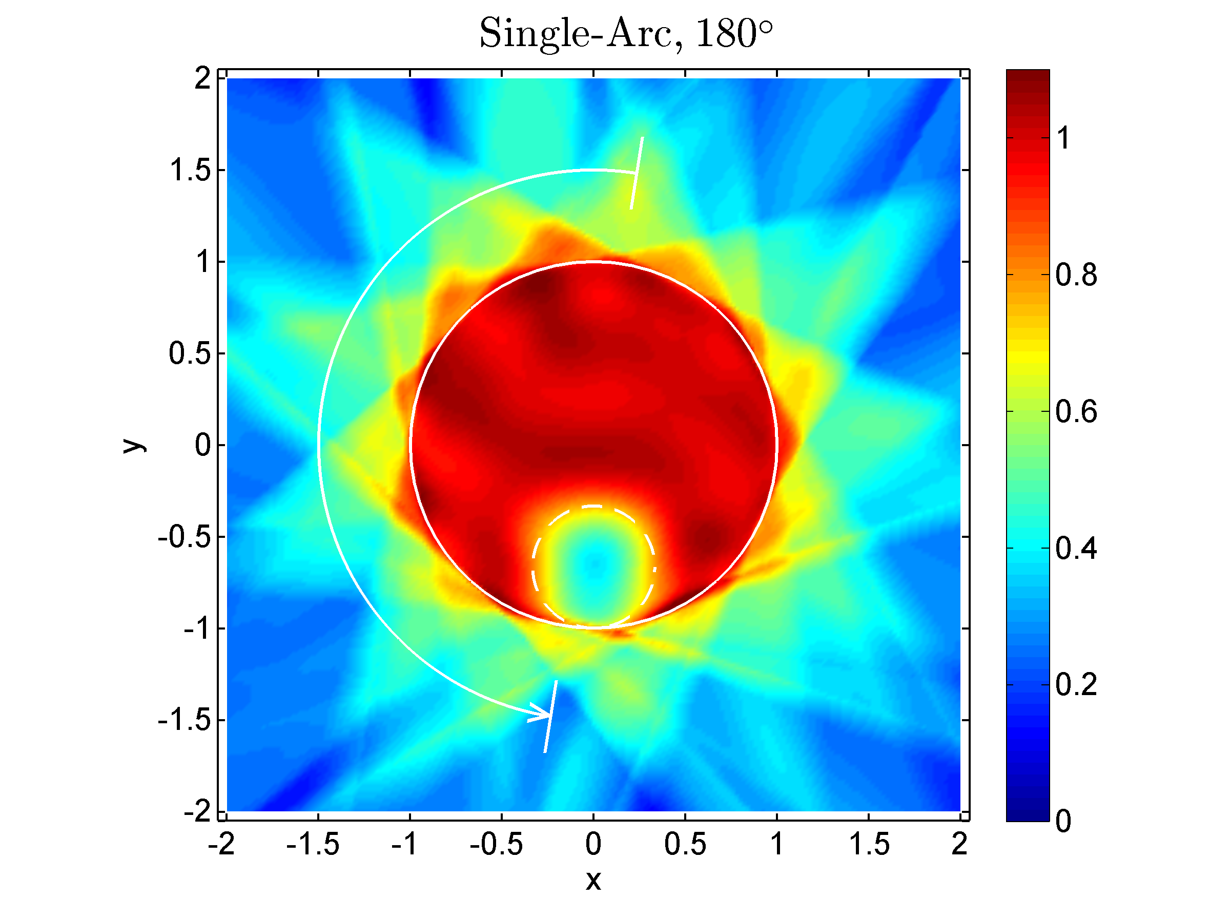
Let us now illustrate the findings above for the example case shown in figure 3. The dose distribution from the first of the 10 beams used in 3(b) (the vertical one at ), is shown in figure 4(a). It is composed of the following Chebyshev polynomials: . Note that there are only polynomials of even degree in this beam profile because of the left-right symmetry of the example case. The effect of gantry motion is simulated over an arc segment of , from to , during the delivery of this beam. The gantry rotates counter-clockwise. The leaf motion is from left to right. Thus, in the upper half of figure 4(b), the resulting motion of the field edges in the -direction is reduced by the gantry motion (retrograde motion), and the effect is modeled with equation (28) with negative . In the lower half, which exhibits prograde motion, equation (7) with positive is applied.
The overall result is that, with motion, the characteristics of the fluence profile are preserved, and the effect of motion appears to be similar to using a divergent beam. In Single-Arc, the effect is reduced because the MLC moves back and forth during a rotation of the gantry, i.e., there is an alternation between retrograde and prograde motion. The total dose distribution, which results from combining the 10 arc segments according to the 10 beams used in figure 3(b), is shown in figure 5. Comparing the two figures (3(b) and 5), one can see that the effects on the dose distribution within the unit circle encompassing the target and the critical structure are small. A numerical analysis reveals that the average (RMS) difference is 0.02, i.e., 2% of the prescribed dose. Outside of the unit circle, some noticeable smoothing occurs in Single-Arc, and the differences are bigger. One can also see that the Single-Arc solution is slightly asymmetric. Incidentally, if an odd number of beams had been used in this example, the solution would have been perfectly left-right symmetric.
7 Discussion
In this paper an attempt was made to approach the beam angle problem in IMRT from a fundamental theoretical direction. The objective was to derive analytical expressions that would allow one to draw some generally applicable, rather than case-specific, conclusions. Indeed this objective has been met. However, it could only be accomplished at the price of a strongly simplified model. The question arises: what is the validity of the findings in the real world? I claim that the results remain valid if one uses more realistic dose models, and provide the following arguments in support of this statement. The physical effects that were neglected in the oversimplified model, i.e., dose build-up, (exponential) dose fall-off, and beam divergence, lead to smooth variations from the model. The real world can therefore be modeled by adding small-degree polynomials to the simple model. As long as the degree of these correction polynomials does not exceed the maximum degree polynomial used in the model, the conclusions remain valid.
With respect to the determination of the required number of beams, I should emphasize that equation (6) can only serve as a rough estimate. First, in the interpretation of the Chebyshev polynomials as a series of peaks, I ignored the variation of the peak widths (see figure 1) and just considered the average width. A more careful analysis would have to take the variation in width into account. Secondly, strictly speaking equation (6) is only valid if one allows negative beam intensities. I address the negativity issue by use of the zero-offset idea mentioned above. However, the total zero-offset depends on the number of beams. A more detailed analysis would have to take this second-order effect, which was also mentioned in section 4 above, into account. Third, the number calculated with equation (6) is not a strict practical limit on the number of beams. In fact, smaller numbers of beams suffice to obtain approximate solutions. Along similar lines, it is clear that the required number of beams may also depend on the specific geometry of the target volume and the surrounding critical structures, i.e, simple cases require less beams. This paper does not provide a case-specific analysis of the number of beams, because a general answer is sought after.
As far as Single-Arc is concerned, a potential criticism of this work is that the theory is only two-dimensional. This would not be a problem as long as the real 3D solution can be composed of 2D slices. However, in a 2D model one cannot model collimator rotation. Others have found that in Single-Arc a 45∘ collimator rotation leads to better results [Otto2008] than if the MLC leaves move within the transversal planes, as in this paper. It is not completely clear where the advantage of a 45∘ collimator comes from. It has been hypothesized that this advantage is due to the fact that, with the collimator at 45∘, in parallel opposed beams the leaves of the MLC move in orthogonal directions. In other words, parallel opposed beams are not redundant (unlike in the present model with a flat dose profile, where they would indeed be redundant). It should be kept in mind, however, that the model here assumes a gantry rotation of only about 180∘. Hence, the delivery could be faster, maybe twice as fast, as a Single-Arc treatment over 360∘ with a 45∘ collimator rotation. The 45∘ collimator rotation may be of no advantage if the Single-Arc angle is restricted to 180∘.
With respect to future developments, the idea to decompose beam profiles into well-behaved smooth functions, such as Chebyshev polynomials, may not only be of interest for the analysis of the required number of beams, but it could also be beneficial for general IMRT treatment planning and optimization.
8 Conclusions
In IMRT the required number of beams depends directly on the complexity of the fluence (intensity) profiles that can be delivered within the physical and technical constraints of the treatment machine. One can measure the fluence complexity by the degree of the Chebyshev polynomial that is required to approximate the profile. The required number of beams then equals the highest degree polynomial plus 1. Rotating the beams over short arc segments between the fixed beam positions merely causes the dose distribution to fan out, but does not normally alter it substantially. This, in combination with the first conclusion above, serves as a theoretical justification of single-arc IMRT (VMAT).
Appendix A The impact of gantry rotation on leaf sweep IMRT delivery
Let us first review the mathematical basis of leaf sweep MLC delivery. Consider a (non-negative) fluence profile in the interval such that . One can always decompose into two components, one of which, , contains all positive slopes and the other, , contains all negative slopes:
| (8) |
where
| (9) |
and
| (10) |
Here equals if , and 0 otherwise. Similarly, equals if , and 0 otherwise. Note that both and are monotonically increasing functions.
Let us first consider . For any argument one can write in the form:
| (11) |
Using integration by parts, i.e., , one obtains further:
| (12) |
because the integral of a delta function is the Heaviside step function, . With the identity one can then easily show that
| (13) | |||||
| (14) |
The case for can be made completely analogously (simply replace with and with ), yielding:
| (15) |
This is indeed the standard uni-directional leaf sequencing algorithm in which the trajectory of the left (A) leaf is given by and the trajectory of the right (B) leaf by . Here one should identify with time, .
A.1 Prograde motion
For the sake of simplicity I will assume that gantry motion adds constant speed, , to the speed of the leaves. Variable speed can be considered but at the expense of a more complex notation. Let us also consider a constant shift, . In the following, the tilde stands for gantry motion, so:
| (16) |
Consider first the case where the gantry motion is in the direction of the moving MLC, that is, in the direction, such that is positive. From equation (14) (tilde version) one obtains, using integration by parts:
| (17) | |||||
| (19) |
Here and . The first term in equation (19) is zero. Now use the relationship , where are the roots of . In this case there is one root of , which is . The denominator of the relationship for cancels out the term in equation (19). This leaves us with:
| (20) | |||||
| (21) |
which can be written in the form:
| (22) |
Similarly,
| (23) |
This means that is just with variable shifts in the direction of . However, because those shifts can be different for and , the impact on can be more substantial.
An even simpler way to understand the impact of gantry motion is by looking at the gradient of the fluence profile. From equation (16) one can see that
| (24) |
or
| (25) |
Hence, in areas with large gradients of , the gradient of will converge to . Areas with small gradients will not be affected.
A.2 Retrograde motion
Now let us look at the case where the gantry motion is in the opposite direction of the moving MLC, that is, in the direction, which means that is negative. This is more complicated because now the MLC leaves can move in both directions, i.e., is no longer necessarily monotonic. As one can see from equation (16), leaves move backwards, i.e., has a negative slope (and so does, consequently, ) if . Let us first look at again.
From equation (19) it follows that in this case
| (26) |
where the are, again, the roots of , and if the slope of is negative at , and otherwise.
Now the task is to calculate . One can keep this problem tractable by subdividing the fluence interval into contiguous sub-intervals such that and . The sub-intervals are chosen such that in the -th sub-interval , and thus , is either monotonically increasing or decreasing, in an alternating sequence. The corresponding intervals are , where and . It is now clear that there can be at most roots .
Now define
| (27) |
which are the monotonic segments with ‘zero-padding’. One can see that . Hence, at the roots one gets . This yields the final result
| (28) |
One can understand this result intuitively as follows: Assume that for any given point the MLC leaf crosses that point twice, once, in segment , in the direction, and then, in segment , in the direction. The total fluence is then simply , because this is how long point is irradiated. If the leaf crosses the point multiple times, the total fluence is exactly as given by equation (28) above.
In words, equation (28) means that the fluence delivered is the sum of compressed segments from the original (no motion) fluence profile, and the negative terms therein ensure a contiguous transition between those segments. For one gets the result simply by replacing all ‘’ in the exponent with ‘’. The total overall fluence is .
Acknowledgment
I would like to thank Drs Steve Webb and Dualta McQuaid from the Royal Marsden Hospital in Sutton, UK, for their thoughtful feedback and constructive suggestions on the manuscript. In particular, they worked through the appendix and helped to make it more comprehensible. I would also like to thank my colleague Dr. David Craft from the Massachusetts General Hospital for his thoughtful comments.
This work was supported in part by grants R01-CA118200 and R01-CA103904 from the National Cancer Institute of the USA.
References
References
- [1] \harvarditemBortfeld \harvardand Oelfke1999Bortfeld1999 Bortfeld, T. \harvardand Oelfke, U. \harvardyearleft1999\harvardyearright. Fast and exact 2D image reconstruction by means of Chebyshev decomposition and backprojection, Phys Med Biol 44(4): 1105–20.
- [2] \harvarditem[Bortfeld et al.]Bortfeld, Oelfke \harvardand Nill2000Bortfeld2000 Bortfeld, T., Oelfke, U. \harvardand Nill, S. \harvardyearleft2000\harvardyearright. What is the optimum leaf width of a multileaf collimator?, Med Phys 27(11): 2494–502.
- [3] \harvarditemBortfeld \harvardand Webb2009Bortfeld2009 Bortfeld, T. \harvardand Webb, S. \harvardyearleft2009\harvardyearright. Single-arc IMRT?, Phys Med Biol 54(1): N9–20.
- [4] \harvarditem[Boyer et al.]Boyer, Ochran, Nyerick, Waldron \harvardand Huntzinger1992Boyer1992 Boyer, A. L., Ochran, T. G., Nyerick, C. E., Waldron, T. J. \harvardand Huntzinger, C. J. \harvardyearleft1992\harvardyearright. Clinical dosimetry for implementation of a multileaf collimator, Med Phys 19(5): 1255–61.
- [5] \harvarditemCameron2005Cameron2005 Cameron, C. \harvardyearleft2005\harvardyearright. Sweeping-window arc therapy: an implementation of rotational IMRT with automatic beam-weight calculation, Phys Med Biol 50(18): 4317–36.
- [6] \harvarditemCarol1994Carol1994 Carol, M. P. \harvardyearleft1994\harvardyearright. Integrated 3-D conformal multi-vane intensity modulation delivery system for radiotherapy, XIth International Conference on the Use of Computers in Radiation Therapy, Christie Hospital NHS Trust, Manchester, UK, Manchester, UK, pp. 172–173.
- [7] \harvarditemConvery \harvardand Rosenbloom1992Convery1992 Convery, D. \harvardand Rosenbloom, M. \harvardyearleft1992\harvardyearright. The generation of intensity-modulated fields for conformal radiotherapy by dynamic collimation, Physics in Medicine and Biology 37(6): 1359–1374.
- [8] \harvarditemCormack1987Cormack1987 Cormack, A. M. \harvardyearleft1987\harvardyearright. A problem in rotation therapy with x rays, Int J Radiat Oncol Biol Phys 13(4): 623–30.
- [9] \harvarditemCormack \harvardand Cormack1987Cormack1987a Cormack, A. M. \harvardand Cormack, R. A. \harvardyearleft1987\harvardyearright. A problem in rotation therapy with x-rays: dose distributions with an axis of symmetry, Int J Radiat Oncol Biol Phys 13(12): 1921–5.
- [10] \harvarditemCormack \harvardand Quinto1989Cormack1989 Cormack, A. M. \harvardand Quinto, E. T. \harvardyearleft1989\harvardyearright. On a problem in radiotherapy: questions of non-negativity, International Journal of Imaging Systems and Technology 1: 120–124.
- [11] \harvarditem[Mackie et al.]Mackie, Holmes, Swerdloff, Reckwerdt, Deasy, Yang, Paliwal \harvardand Kinsella1993Mackie1993 Mackie, T. R., Holmes, T., Swerdloff, S., Reckwerdt, P., Deasy, J. O., Yang, J., Paliwal, B. \harvardand Kinsella, T. \harvardyearleft1993\harvardyearright. Tomotherapy: a new concept for the delivery of dynamic conformal radiotherapy, Med Phys 20(6): 1709–19.
- [12] \harvarditemMohan \harvardand Ling1995Mohan1995 Mohan, R. \harvardand Ling, C. C. \harvardyearleft1995\harvardyearright. When becometh less more?, Int J Radiat Oncol Biol Phys 33(1): 235–7.
- [13] \harvarditemOtto2008Otto2008 Otto, K. \harvardyearleft2008\harvardyearright. Volumetric modulated arc therapy: IMRT in a single gantry arc, Med Phys 35(1): 310–7.
- [14] \harvarditem[Ulrich et al.]Ulrich, Nill \harvardand Oelfke2007Ulrich2007 Ulrich, S., Nill, S. \harvardand Oelfke, U. \harvardyearleft2007\harvardyearright. Development of an optimization concept for arc-modulated cone beam therapy, Phys Med Biol 52(14): 4099–119.
- [15] \harvarditem[Wang et al.]Wang, Luan, Tang, Chen, Earl \harvardand Yu2008Wang2008 Wang, C., Luan, S., Tang, G., Chen, D. Z., Earl, M. A. \harvardand Yu, C. X. \harvardyearleft2008\harvardyearright. Arc-modulated radiation therapy (amrt): a single-arc form of intensity-modulated arc therapy, Phys Med Biol 53(22): 6291–303.
- [16] \harvarditemWebb \harvardand McQuaid2009Webb2009 Webb, S. \harvardand McQuaid, D. \harvardyearleft2009\harvardyearright. Some considerations concerning volume-modulated arc therapy: a stepping stone towards a general theory, Phys Med Biol 54(14): 4345–60.
- [17]