119–126
Hydrodynamic simulations of the core helium flash
Abstract
We desribe and discuss hydrodynamic simulations of the core helium flash using an initial model of a 1.25 star with a metallicity of 0.02 near at its peak. Past research concerned with the dynamics of the core helium flash is inconclusive. Its results range from a confirmation of the standard picture, where the star remains in hydrostatic equilibrium during the flash ([Deupree (1996), Deupree 1996]), to a disruption or a significant mass loss of the star ([Edwards (1969), Edwards 1969]; [Cole & Deupree (1980), Cole & Deupree 1980]). However, the most recent multidimensional hydrodynamic study ([Dearborn et al. (2006), Dearborn et al. 2006]) suggests a quiescent behavior of the core helium flash and seems to rule out an explosive scenario. Here we present partial results of a new comprehensive study of the core helium flash, which seem to confirm this qualitative behavior and give a better insight into operation of the convection zone powered by helium burning during the flash. The hydrodynamic evolution is followed on a computational grid in spherical coordinates using our new version of the multi-dimensional hydrodynamic code HERAKLES, which is based on a direct Eulerian implementation of the piecewise parabolic method.
keywords:
Stars: evolution – hydrodynamics – convection1 Introduction
First results on the core helium flash were gained from one-dimensional hydrostatic numerical simulations of a 1.3 star (Z=0.001) (e.g., [Schwarzschild & Härm (1962), Schwarzschild & Härm 1961]). During the flash, the star underwent a thermal runaway due to the ignition of helium under degenerate conditions in its center. It reached a peak at maximum core temperature of and total energy generation rate of . The calculations were redone later with better numerical techniques and improved treatment of major physical processes ([Sweigart & Gross (1978), Sweigert & Gross 1978]) and although the ignition of helium occured off-center due to neutrino processes, they did not change the general picture mentioned earlier. It turns out, that the typical e-folding times for the energy release from helium burning become as low as hours at the peak of the flash, and therefore are comparable to convective turnover times. Thus, the usual assumptions used in simple descriptions of convection in one-dimensional hydrostatic calculations (e.g. instantaneous mixing) do not have to be valid any longer. Previous attempts to relax these assumptions by allowing for hydrodynamic flow remained inconclusive ([Edwards (1969), Edwards 1969]; [Deupree (1996), Deupree 1996]; [Dearborn et al. (2006), Dearborn et al. 2006]). Using a modified version of the HERAKLES code ([Kifonidis et al. (2003), Kifonidis et al. 2003]) which is capable of solving the hydrodynamic equations coupled to nuclear burning and thermal transport in up to three spatial dimensions, we want to deepen our understanding of the convection during the core helium flash at its peak investigating it by means of two-dimensional and three-dimensional hydrodynamic simulations.
2 Initial setup
The initial model was obtained with the stellar evolution code GARSTEC ([Weiss & Schlattl (2007), Weiss & Schlattl 2007]). Some of its properties are listed in Table 1. The temperature, density and composition distribution of the model is depicted in Figure 1. The model encompasses a white dwarf-like degenerate structure with an off-center temperature maximum resulting from plasma- and photo-neutrino cooling and a central density of about g cm-3. The isothermal region in the center of the helium core is followed by almost discontinuous jump in temperature up to and convection zone driven by the superadiabatic temperature gradient. The model is composed mostly of helium 4He with an abundance X(4He) 0.98. The remaining composition of the stellar model is 1H, 3He, 12C, 13C, 14N, 15N and 16O. For our hydrodynamic simulations we adopt the abundances of 4He, 12C and 16O from the initial model, since the triple- reaction dominates the nuclear energy production rate during the flash. The remaining composition is assumed to be adequately represented by a gas with a mean molecular weight equal to that of 20Ne.


| Model | Pop. | ||||||||
|---|---|---|---|---|---|---|---|---|---|
| M | I |
3 Hydrodynamic simulations
Table 2 summarizes some characteristic parameters of our two-dimensional (2D) and three-dimensional (3D) simulations that are based on model M. They were performed on an equidistant spherical grid encompassing 95% of the helium core’s mass except for a central region with a radius of r , which was excised in order to allow for larger timesteps.
| run | ||||||||||
|---|---|---|---|---|---|---|---|---|---|---|
| DV2 | 5.55 | 2.∘ | - | 4.7 | 1.03 | - 6. | 7. | 910 | 30000 | |
| DV4 | 2.77 | 0.75∘ | - | 4.7 | 1.52 | +92. | 14. | 620 | 60000 | |
| TR | 5.55 | 1.5∘ | 1.5∘ | 4.7 | 0.7 | +6. | 7. | 1340 | 5300 |
All our 2D and 3D models undergo initially (t 1200 s) a common evolution where convection sets in after roughly 1000 s. During this phase, hot bubbles appear in the region where helium burns in a thin shell (rcm). After 200 s, they cover complete height of the convective region and reach a steady state with several upstreams (or plumes) of hot gas carrying the released nuclear energy away from the burning region, thereby inhibiting a thermonuclear runaway.

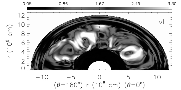


Fully evolved convection (t 1500 s) in 3D is significantly different than in 2D, since the shape of turbulent streams which transport energy is totally distinct. However, the amount of energy which needs to be transported by the convection in order to prevent a thermonuclear runaway during the flash is in both cases similar. The resulting typical convective velocities are therefore much higher in 2D than in 3D (Fig. 3).
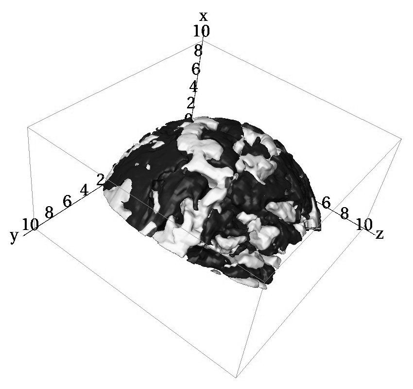
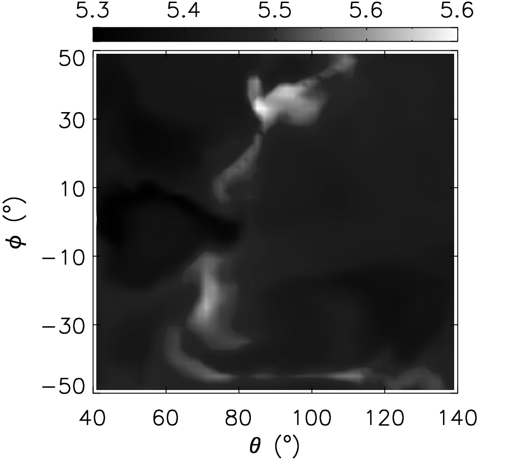
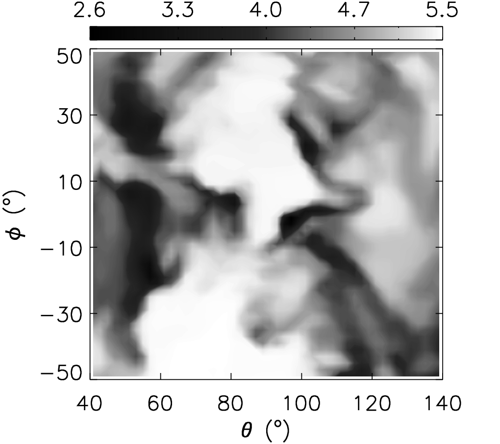
The structural differences between 2D and 3D flows are clearly visible in the distribution of the kinetic flux across the convection zone (Fig. 3). The typical evolved 2D flows contain well defined vortices (Fig. 2) with their central regions never interacting with the region of the dominant nuclear burning above the . This results in a reduced kinetic flux between r , since the gas in that region, on average, is located at bottom of convective vortices, and thus does not experience any strong radial flow. On the other hand, the distribution of the kinetic flux in 3D is rather smooth, and the flow structures tend to be also smaller than in 2D. This is apparent when comparing Figure 4 with Figure 2. The 2D structures (vortices) have an angular size of around . The structures in the 3D are column shaped, with a smaller angular size. The convective and kinetic flux is lower in 3D than in the 2D, but the total energy production is about 20 % higher in 3D (because no symmetry restrictions are imposed, and due to the strong dependence of the triple- reaction rate on the temperature). The convective and kinetic flux carry together more than 90 % of the energy produced by the burning. The 3D velocities qualitatively match the velocities predicted by the mixing-length theory better than in 2D, where the velocities are clearly overestimated. Figure 3 shows that they also depend on resolution, being higher in the simulation with the highest resolution.
The extent of the convection zone increases with time. Due to turbulent entrainment ([Meakin & Arnett (2007), Meakin & Arnett 2007]), convective boundaries defined by the Schwarzschild criterium are pushed towards the center of the star, and towards the stellar surface, respectively (Fig. 3). This is in contradiction with the predictions made by (1D) hydrostatic stellar modeling. For ilustration, the temporal evolution of the location of the outer convective boundary is depicted in Figure 3. It is defined as the radius, where the mean carbon abundance X(12C ) 0.002. The rapid initial jump of the boundary position to r at about 1200 s is due to the first touch of the convective flow on the boundary. Later entrainment is rather steady. The velocity of the outer boundary (entrainment rate) in our models are listed in Table 2. The entrainment involves a few radial zones only over the longest simulation we have performed. Although the 12C abundance distribution stayed discontinuous at boundaries (no evident effect of numerical diffusion is detected), the entrainment rates presented here have to be considered as an order of magnitude estimate only. The entrainment at the inner convective boundary occurs with a rate much smaller than at the outer convective boundary. Therefore it is not discussed further here, since longer simulations are needed for definite statements about its evolution.
A similar feature which 2D and 3D seem to share is the upflow-downflow asymmetry. The downflows cover a much bigger volume in the convection zone than the upflows. The downflows dominate more in 3D. Interestingly, the kinetic flux is always positive in both cases, although the downflows fill almost the whole convection zone. This implies that the downflows are much slower then the upflows.
The expansion velocities v are in good agreement with those of initial stellar model only in the 2D model with highest resolution DV4 (Fig. 3). The expansion in the low resolution models does not match at all. Due to the different dynamic properties of the flow in the less resolved models, the spherical mass flow is weaker.
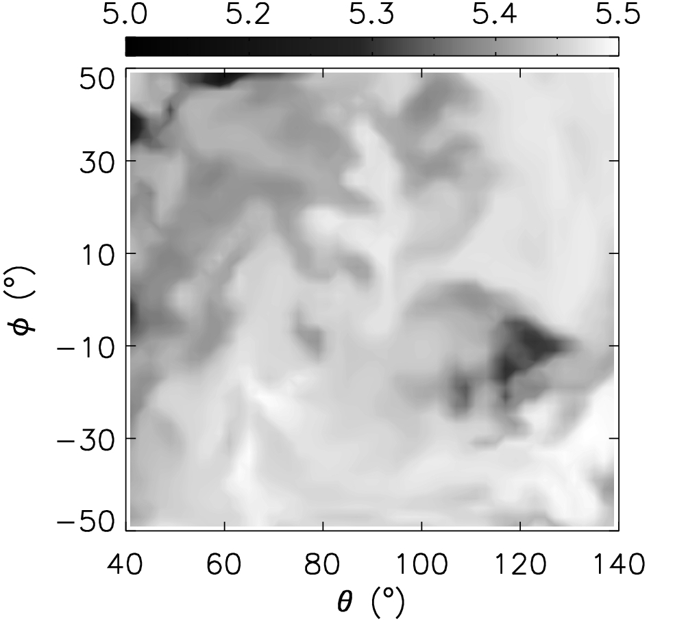
Mixing at the convective boundaries and across the convection zone in 2D and 3D is quite different as well. In 2D, due to the symmetry restriction, every turbulent feature is in fact an annulus. Hence, turbulence and mixing can be properly modelled only by means of 3D simulations. The most apparent turbulent structures during the flash, in 3D, look at the bottom of the convection zone like thin hot fibers enriched by carbon and oxygen (ashes from the helium burning). The flow then gets more uniform inside the convective region, but looks more turbulent again at the outer convective boundary (Fig. 5).
4 Conclusions
We find that the core helium flash neither rips the star apart, nor significantly alters its structure. The evolved convection in 3D looks different from that in 2D. Typical convective velocities are higher in 2D than in 3D where they also tend to fit the predictions made by mixing length theory better. Hydrodynamic simulations show the presence of turbulent entrainment, which results in a growth of the convection zone on dynamic time scales.
Acknowledgements.
The calculations were performed at the Leibniz-Rechenzentrum of the Bavarian Academy of Sciences and Humanities on the SGI Altix 4700 system. A considerable grant of computer time is thankfully acknowledge.References
- [Cole & Deupree (1980)] Cole, P.W., Deupree, R.G., 1980, ApJ, 239, 284
- [Deupree (1996)] Deupree, R.G., 1996, ApJ, 471, 377
- [Dearborn et al. (2006)] Dearborn D.S.P., Lattanzio J.C., Eggleton P., 2006, ApJ, 639, 405
- [Edwards (1969)] Edwards, A.C., 1969, MNRAS 146, 445
- [Hurlburt et al. (1986)] Hurlburt,N.E., Toomre, J.,& Massaguer, J.M., 1986, ApJ, 311,563
- [Kifonidis et al. (2003)] Kifonidis K., Plewa,T., Janka H-Th., Müller E., 2003,A&A, 408, 621
- [Meakin & Arnett (2007)] Meakin, C.A., Arnett D., 2007, ApJ, 667, 448
- [Sweigart & Gross (1978)] Sweigart A.V., Gross P.G., 1978, ApJS, 36, 405
- [Schwarzschild & Härm (1962)] Schwarzschild M., Härm R.,1962, ApJ, 136, 158
- [Weiss & Schlattl (2007)] Weiss A., Schlattl H., 2007, Ap&SS, 341