Gravitational Instabilities, Chondrule Formation, and the FU Orionis Phenomenon
Abstract
Using analytic arguments and numerical simulations, we examine whether chondrule formation and the FU Orionis phenomenon can be caused by the burst-like onset of gravitational instabilities (GIs) in dead zones. At least two scenarios for bursting dead zones can work, in principle. If the disk is on the verge of fragmention, GI activation near to 5 AU can produce chondrule-forming shocks, at least under extreme conditions. Mass fluxes are also high enough during the onset of GIs to suggest that the outburst is related to an FU Orionis phenomenon. This situation is demonstrated by numerical simulations. In contrast, as supported by analytic arguments, if the burst takes place close to AU, then even low pitch angle spiral waves can create chondrule-producing shocks and outbursts. We also study the stability of the massive disks in our simulations against fragmentation and find that although disk evolution is sensitive to changes in opacity, the disks we study do not fragment, even at high resolution and even for extreme assumptions.
1 Introduction
1.1 GIs, MRI, FU Orionis Outbursts, and Chondrules
Gravitational instabilities can activate in a disk when the Toomre (1964) parameter for a thick disk (see Durisen et al. 2007), where is the sound speed, is the surface density, and is the epicyclic frequency. As indicated by , a disk is unstable against GIs when it is cold and/or massive. The resulting spiral waves driven by self-gravity efficiently transfer angular momentum outward and mass inward (e.g., Lynden-Bell & Kalnajs 1972; Durisen et al. 1986). Another mechanism that can efficiently transfer angular momentum outward is the magnetorotational instability (MRI; see Balbus & Hawley 1991; Desch 2004). In contrast to GIs, the MRI only requires a weak magnetic field coupled to the gas. These mechanisms, either separately or in combination, are likely to be the principal way T Tauri stars accrete gas from a disk (Hartmann et al. 2006).
In order for the MRI to occur, ionized species must be present in the gas phase. Thermal ionization of alkalis occurs wherever K, but depletion of ions by dust grains may move the temperature threshold closer to K (Desch 1999; Sano et al. 2000), where the dust sublimates completely. Elsewhere, the ionization must be driven by a nonthermal source, e.g., energetic particles (EPs). For this discussion, EPs refers to any particles that could ionize the gas, e.g., X-rays. Gammie (1996) proposed that disks may have active and inactive MRI layers due to attenuation of EPs by the gas. In the inner regions of a disk (at radii few AU) where the column densities are large, MRI may only be active in a thin layer, resulting in layered accretion. As one moves outward, column densities drop, and the entire disk can become MRI active. The region where the MRI is mostly absent is called the dead zone. EPs are attenuated by a surface density of only about 100 g cm-2 (Stepinski 1992), and so even a minimum mass solar nebula (MMSN) will likely exhibit layered accretion (Desch 2004). Even if mass accretion is only reduced and not altogether halted as a result of Reynolds stresses (Fleming & Stone 2003; Oishi et al. 2007), mass may still pile up in the dead zone. If enough mass accumulates, then even for an otherwise low-mass disk, GIs can activate.
The FU Orionis phenomenon is characterized by a rapid (1-10s yr) increase in optical brightness of a young T Tauri object, typically by 5 magnitudes, and is driven by sudden mass accretion of the order from the inner disk onto the star (Hartmann & Kenyon 1996). Because FU Ori objects appear to have decay timescales of about 100 yr, the entire mass of a MMSN () can be accreted onto the star. To date, the best explanation for the optical outburst is a thermal instability (e.g., Bell & Lin 1994; Kley & Lin 1999; see discussions in Hartmann & Kenyon 1996, Green et al. 2006; and Zhu et al. 2007). Armitage et al. (2001) suggested that GIs in a bursting dead zone might be able to trigger an FU Ori outburst by rapidly increasing the accretion into the inner disk ( AU) and initiating an MRI through thermal ionization. Hartmann (2007, in private communication) and Zhu et al. (2007) also suggest that the heating due to gravitational torques might drive an MRI for AU, which would then feed mass inside 0.1 AU until a thermal instability sets in. The FU Ori phenomenon may be a result of a cascade of instabilities, starting with a burst of GI activity in a dead zone, followed by accretion due to an MRI, followed finally by a thermal instability (cf Kley & Lin 1999). Indeed, recent observations of FU Ori indicate that very large mass fluxes are present out to at least AU (Zhu et al. 2007).
Although details are still being debated, most chondrules formed in the first 1 to 3 Myr of the Solar Nebula’s evolution (Bizzarro et al. 2004; Russell et al. 2005). Chondrule precursors were flash melted from solidus to liquidus, where high temperatures K were experienced by the precursors for a few minutes. The melts then cooled over hours, with the actual cooling time depending on chondrule type. Chondrule collisional histories and isotopic fractionation data, chondrule-matrix complementarity, fine-grained rim accumulation, and petrological and parent body location arguments (Krot et al. 2005) suggest that chondrules formed in the Solar Nebula (Wood 1963) in strong, localized, repeatable heating events. The shock wave model for chondrule formation can accommodate these observational constraints and reproduce heating and cooling rates required to form chondrule textures (Iida et al. 2001; Desch & Connolly 2002; Cielsa & Hood 2002; Miura & Nakamoto 2006). One plausible source of chondrule-producing shocks is a global spiral wave (Wood 1996). Harker & Desch (2002) suggest that spiral waves could also explain thermal processing at distances as large as 10 AU, which may be necessary to explain observations of comets (Wooden et al. 2005) and recent Stardust results (e.g., McKeegan et al. 2006). It has been suggested that bursts of GIs may be able to produce the required shock strengths (Boss & Durisen 2005) and provide a source of turbulence and mixing (Boss 2004b; Boley et al. 2005). Global spiral shocks are appealing because they fit many of the constraints above. They may be repeatable, depending on the formation mechanism for the spiral waves; they are global, but produce fairly local heating; they can form chondrules in the disk; and they can work in the inner disk as well as the outer disk.
1.2 Fragmentation
Knowing under what conditions protoplanetary disks can fragment is crucial to understanding disk evolution inasmuch as a fragmented disk may produce gravitationally bound clumps. This has become known as the disk instability hypothesis for the formation of gas giant planets (Kuiper 1951; Cameron 1978; Boss 1997, 1998). The strength of GIs is regulated by the cooling rate in disks (Tomley et al. 1991, 1994; Pickett et al. 1998, 2000, 2003), and if the cooling rate is high enough in a low- disk, a disk can fragment (Gammie 2001). Gammie quantified that a disk will fragment when for a disk with a , where is the two-dimensional adiabatic index, such that , where is the gas pressure and is the vertical direction in the disk. Here, is the local cooling time and is the angular speed of the gas. This criterion was approximately confirmed in 3D disk simulations by Rice et al. (2003) and Mejía et al. (2005). Rice et al. (2005) showed through 3D disk simulations that this fragmentation criterion depends on the 3D adiabatic index and, for or 7/5, the fragmentation limit occurs when or 12, respectively. These results show that a change by a factor of about 1.2 in has a factor of two effect on the critical cooling time. In addition, these results indicate that the cooling time must be roughly equal to the dynamical time of the gas for the disk to be unstable against fragmentation when .
Do such prodigious cooling rates occur in disks when realistic opacities are used with self-consistent radiation physics? This question is heavily debated in the literature (e.g., Nelson et al. 2000; Boss 2001, 2004a, 2005; Rafikov 2005, 2007; Boley et al. 2006, 2007b; Mayer et al. 2007; Stamatellos & Whitworth 2008). The simulations to date use a wide variety of numerical methods, including very different approximations for radiation physics, and only two groups have published results of radiative transfer tests appropriate for disks (Boley et al. 2007b; Stamatellos & Whitworth 2008).
Nelson et al. (2000) used 2D SPH simulations with radiation physics to study protoplanetary disk evolution. Because their simulations were evolved in 2D, they assumed that the disk at any given moment was in vertical hydrostatic equilibrium. Using a polytropic vertical density structure and Pollack et al. (1994) opacities, they cooled each particle according to an appropriate effective temperature. In their simulations, the cooling rates are too low for fragmentation. In contrast, Boss (2001, 2005) employed radiative diffusion in his 3D grid-based code; fragmentation occurs in his simulated disks. Besides the difference in dimensionality of the simulations, Boss assumed a fixed temperature structure for Rosseland mean optical depths less than 10, as measured along the radial coordinate (cf recent flux-limited simulations by Boss 2008). Boss (2002) found that the fragmentation in his disks is insensitive to the metallicity of the gas and attributed this independence to fast cooling by convection (Boss 2004a). However, it must be noted that Nelson et al. (2000) assumed a vertically polytropic density structure. Because the specific entropy , where is the polytropic equation of state and is the gas density, the Nelson et al. approximation effectively assumes efficient convection.
Except for extremely massive and extended disks (Stamatellos et al. 2007), recent simulations with radiative physics by Cai et al. (2006), Boley et al. (2006, 2007b), and Stamatellos & Whitworth (2008) find long cooling rates and no efficient cooling by convection. Cai et al. also show that the strength of GIs is dependent on the metallicity. Furthermore, Boley & Durisen (2006) suggest that shock bores, which can cause a rapid vertical expansion in the post-shock region of spiral shocks, could be misidentified as “convective” flows. In both contrast and support of these studies, Mayer et al. (2007) use SPH simulations with 3D flux-limited diffusion and find that fragmentation only occurs once the mean molecular weight of the gas . However, the simulations presented by Mejía (2004), Cai et al. (2006), and Boley et al. (2006) unintentionally were evolved with due to an error in the inclusion of He in the opacity tables, and their disks do not fragment. The issue of fragmentation in radiatively cooled disks thus remains unsettled.
1.3 Current Study
For this study, we adopt the hypothesis, which we refer to as the unified theory, that bursts of GI activity in dead zones drive the FU Ori phenomenon and produce chondrule-forming shocks. This hypothesis is an amalgamation of ideas presented in Wood (1996, 2005), Gammie (1996), Armitage et al. (2001), and Boss & Durisen (2005). In order to investigate this scenario, we designed a numerical experiment to evolve a massive, highly unstable disk with an initial radial extent between 2 and 10 AU. Commensurately, we investigate the stability of these massive, gravitationally unstable disks against fragmentation to assess the feasibility of the disk instability hypothesis for gas giant formation.
2 Expectations
The shock speed for a fluid element entering a global, logarithmic spiral wave with pitch angle is approximately described by
| (1) |
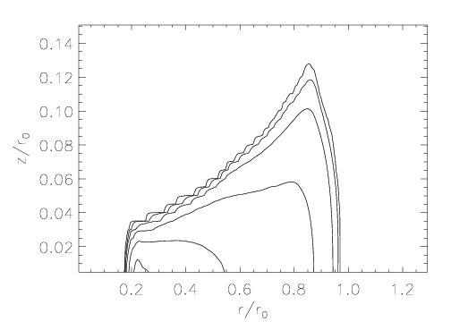
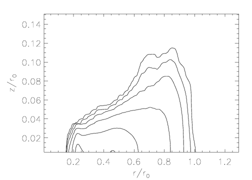
where is the corotation radius of the spiral pattern and where we have assumed that the gas azimuthal motion is Keplerian and is negligible. When , the shock speed limits to the Keplerian speed times ; whether spiral waves with large produce chondrules is mainly dependent on the pitch angle of the spiral wave. In contrast, when , the speed increases as , and even shallow pitch angles can produce chondrules. For example, consider the MMSN, where the midplane g cm-3 (Hayashi et al. 1985). Figure 1 shows the - plane with heavy, solid curves indicating shock speeds for , 2.5, 5, and AU and with and 30∘. The colored regions on the plot highlight where chondrule formation is expected in a MMSN (yellow) and a 10MMSM (orange). The chondrule-forming curves are based on the results of Desch & Connolly (2002), which we summarize by . The boundaries set by these curves are meant to be illustrative, not definitive. Spiral shocks along shallow pitch angle spiral waves () are mostly if not entirely out of the chondrule-forming range between and 5 AU for shocks inside corotation. However, spirals with corotation in the inner disk can produce chondrule-forming shocks for a wide range of radii, depending on the actual . If the spiral waves have very open pitch angles (), then spiral waves with corotation near AU can produce chondrule-forming shocks near the asteroid belt and at cometary distances. The mass of the disk does not change these general behaviors. A major caveat for this simple-minded approach is that the fluid elements’ motions may be poorly described by equation (1) if vertical and radial excursions induced by shock bores (Boley & Durisen 2006) cannot be neglected.
The possibility of producing chondrules in the asteroid belt and at comet distances during the same burst is attractive. Moreover, we would also like to use these simulations to study other phenomena such as radiation transport, convection, and disk fragmentation in the 2-10 AU region. For these reasons, we tried to design a numerical experiment to investigate the connection between GIs, FU Orionis events, and chondrule formation that is biased toward producing strong shocks with a corotation near 5 AU and with open pitch angles.
3 Methodology
3.1 Initial Conditions
If chondrule-producing shocks cannot be created in simulations biased in their favor, then it would present a serious problem for GIs as the source of chondrule processing. The reader should keep in mind that the model, at this stage, is not necessarily meant to be representative of a typical disk, although the massive disk we present may be plausible for early Class I objects (e.g., L1551; Osorio et al. 2003). To create the initial conditions (ICs), consider a disk that is vertically polytropic, is axisymmetric, has a constant , and is Keplerian (). Also assume that self-gravity is negligible. With these assumptions, the vertical disk structure can be calculated by using the following equations:
| (2) | |||||
| (3) | |||||
| (4) |
where for is the polytropic coefficient at any given , is the gravitational constant, is the Keplerian angular speed, and is the disk scale height. Using equations (2) through (4), one can show that
To select a model, one needs to specify power laws for and , and , or and . For calculating , the midplane sound speed is used. Note that when constant, there exists a lower limit for , , where the radial entropy gradient remains positive. Because the specific entropy , equation (5) can be solved to show that for constant . The critical surface density power law is then for and for . When , radial thermal convection may set in for a constant disk. However, the radial entropy gradient is not the only stability criterion for radial thermal convection in disks (Klahr & Bodenheimer 2003).
Equations (2) through (5) are used to generate the ICs for this study. The disk is massive, , with , initially between about 2 and 10 AU in radius and with a everywhere. Although the surface density power law is steep, it is consistent with the Nice-MMSN (Desch 2007).111This model for the MMSN is derived in a way similar to Weidenschilling’s (1977) approach; but, instead of using the current positions of Solar System planets, Desch uses initial positions based on the Nice model (e.g., Levison et al. 2007). Because the analytic model ignores self-gravity, assumes a constant (see §3.2 below), and has sharp disk truncation edges, the model must be relaxed to a new equilibrium structure in the hydro code. Once the ICs are generated, they are loaded into our code and evolved without cooling at very low azimuthal resolution, essentially two-dimensionally. The radial and vertical momenta are damped to allow the disk to relax calmly to an equilibrium configuration, which takes about ten orbits at 10 AU. To create a mass concentration in the disk, mass is then added to the disk linearly in time with a Gaussian profile. The specific internal energy is held constant. The peak of the Gaussian is centered on 5 AU. The radial FWHM of the Gaussian is chosen to be 3 AU, which is roughly the size of the most unstable radial wavelength (Binney & Tremaine 1987). Mass is added until nonaxisymmetry is visible in midplane density images, which takes approximately 190 yr, i.e., 6 orp of evolution (1 orp is defined as 1 outer rotation period at 10 AU for this model, which is about 33 yr). The total mass added is about 0.08 , and so if one were to imagine a corresponding accretion rate, it would be about yr-1. It is probably unphysical to add so much mass so quickly to the disk without increasing the temperature. However, we remind the reader that the study is a numerical experiment. Figures 2 and 3 illustrate the density distributions of the disk before and after the mass accretion.
The mass buildup increases the total mass of the simulated disk to M⊙ and it decreases below unity in a narrow region around 5 AU just before strong GI activation. Because the ring is grown over 6 orp, the instability is not obviously overshot. The mass-weighted average over the FWHM of the Gaussian centered at 5 AU is approximately unity when the ring becomes unstable. This implies that must approach unity for a spatial range of at least the most unstable radial wavelength before GIs will activate in a disk.
3.2 CHYMERA
The disk is evolved with the CHYMERA code (Boley 2007), which employs the Boley et al. (2007b) radiation physics algorithm. CHYMERA is an Eulerian code that solves the hydrodynamics equations on a fixed, cylindrical grid. The code includes self-gravity, a ray+flux-limited diffusion hybrid scheme, and a variable first adiabatic index . This code has been extensively tested. In response to criticisms of Boss’s (2001, 2002, 2004a, 2005) simulations by Boley et al. (2007a), Boss (2007) questions the accuracy of the Indiana University code, which is the predecessor of CHYMERA. Boss raises concerns that we address here.
Potential Solver: CHYMERA uses a direct Poisson solver to calculate the potential due to mass on the grid. To provide the boundary conditions for the direct solver, a spherical harmonics expansion for is used to calculate the potential on the grid boundary (e.g., Pickett et al. 2003; Boley et al. 2007b) . Boss argues that the boundary solver used in CHYMERA may be too low-order to capture clump formation. Tests by Pickett et al. (2003) and Mejía et al. (2005) and the results from the Wengen Test 4 code comparison (WT4; Mayer et al. 2008, in prep.) demonstrate that this is not the case. During the initial analyses of WT4, the potential solver was rigorously tested in an attempt to explain some deviations noticed between CHYMERA and other codes. These deviations were finally attributed to differences in the initial conditions, and new simulations with consistent ICs show very good agreement between codes. To test the potential solver in CHYMERA, a high-order Bessel function expansion boundary solver (Cohl & Tohline 1999) was employed with Legendre half-integer polynomials expanded out to , which showed convergence to better than when compared with . The spiral structure and clump formation in the simulation with this high- boundary solver were indistinguishable from the normal lower-order spherical harmonics expansion. The Wengen test is very demanding, with strong nonaxisymmetric structure and a highly flattened disk, and yet the lower-order spherical harmonics expansion for used in CHYMERA (e.g., Boley et al. 2007b) captures clump formation.
Resolution & Numerical Heating: The resolution for the high-resolution simulations presented in this paper are at higher resolution than the base simulations presented for Wengen Test 4. As will be demonstrated here, CHYMERA shows fragmentation when it is expected based on experimentally determined fragmentation criteria (Gammie 2001; Rice et al. 2005). The numerical heating reported by Boley et al. (2006) affected a small region of their inner disk, and is understood to be a resolution effect. The simulations presented here are at high enough resolution, as determined by the Boley et al. (2007b) tests, that this effect should be negligible if present at all.
Radiative Transfer Boundary Conditions: CHYMERA has been shown to relax to analytic solutions for the flux through an atmosphere as well as the temperature profile for high, moderate, and low optical depths. The code allows convection when it should, and does not when it should not (Boley et al. 2007b).
For the treatment of H2, we use a frozen ortho/para ratio of 3:1 in this study for reasons presented in Boley et al. (2007a). The grain size distribution is assumed to follow the ISM power law, (D’Alessio et al. 2001), where the maximum grain size is chosen to be 1 mm to account for grain growth (D’Alessio et al. 2006). To transition smoothly between the low and high optical depth regimes, a weighted combination between Rosseland and Planck mean opacities is used , where is the vertical midplane Rosseland optical depth. Different methods for interpolating and along the ray are being explored, but they have not been implemented here. The particles are assumed to be well-mixed with the gas. The effect of dust settling is heuristically considered by evolving the disk in several ways: standard opacity and , , and of the standard opacity, referred to as the , , and simulations. This choice in opacities varies the vertical midplane Rosseland mean optical depths from about to unity, and spans the limits where advection of photons becomes important (; Krumholz et al. 2007) and where radiative cooling becomes most efficient (). No external radiation is assumed to be shining onto the disk, except for a 3 K background temperature. Although such rapid dust settling and a naked disk are likely to be unrealistic, the assumptions are made to bias the disk toward strong shocks inasmuch as irradiation and opacity affects GI strength (Cai et al. 2006, 2008). For a base comparison, an adiabatic simulation, i.e., where shock heating is allowed but not cooling, is evolved for about 33 yr.
The simulations are evolved at two resolutions: and cells, respectively, above the midplane. The lower resolution simulations (512 sim) have a grid spacing of 0.05 AU per cell in and and the higher 0.025 AU (1024 sim). For both resolutions, at about AU. These parameters are summarized in Table 1. For each disk, 1000 fluid tracer elements are randomly distributed in between about 3 and 7 AU, in over , and in roughly within the scale height of the disk.
Due to inefficient cooling in the standard simulations, high enough temperatures in the disk are reached after 80 and 55 yr for the 512 and 1024 simulations, respectively, to create radiative timescales that are too short to resolve; the simulations are stopped. As described below, the reduced opacity simulations are able to cool much more efficiently, and the disk temperatures remain manageable with the time-explicit algorithms used in CHYMERA. However, the reduced opacity simulations are stopped after about 110 yr due to the development of a strong, one-arm spiral, which is treated incorrectly with our fixed-star assumption.
3.3 Fluid Element Tracer
The hydrodynamics scheme in CHYMERA is Eulerian, and does not give direct information on the histories of tracer fluid elements. In order to derive detailed and statistical shock information and to capture the complex gas motions in unstable disk simulations, we have combined a tri-Akima spline interpolation algorithm with a Runge-Kutta integrator (e.g., Press 1986) for tracing a large sample of fluid elements during the simulation. Velocities and thermodynamic quantities, e.g., temperature and density, are interpolated once each time step. Because the hydrodynamics code explicitly solves the equation of motion for the gas, the algorithm only needs time and velocity information to integrate the positions of the fluid elements. The Runge-Kutta integrator was intended to be fourth-order accurate; unfortunately, an implementation error when combining the integration scheme into CHYMERA resulted in a first-order accurate scheme in time. Because tracing fluid element histories is an important point of this paper, we reran a stretch of one of the simulations with a second-order fluid element tracing routine. After about one orbit at AU, the mean fractional differences, , between the first and second-order schemes are , , and for , , and , respectively. The sample standard deviations are , , and for , , and , respectively. The mean differences are small, and show that there are no obvious systematic effects. The sample deviations indicate that the variations between the the two schemes are also marginal for the radial and azimuthal directions. There is considerably larger scatter in the vertical direction, where spiral shocks can create complicated vertical flows (Boley & Durisen 2006). Because the fluid elements are used to gather shock information, the scatter in the vertical positions between the two schemes is not a major concern for this study. The effect is similar to redistributing the fluid elements vertically, keeping the same and , every few orbits.
An Akima spline is similar to a natural cubic spline, but typically yields better results for curves with sudden changes (see Akima 1970), as are expected in shock profiles. Although the spline fits a curve to a one-dimensional set of data points, the interpolation can be extended to data in three dimensions. First, consider a cubic volume with data at the vertices. A value anywhere in the volume can be approximated by seven linear interpolations: four to calculate values between each vertex in a particular direction, two to calculate the values along the projections of the desired point onto the interpolated lines, and a final interpolation through the point of interest. Extending this from a simple tri-linear fit to a tri-Akima spline is relatively straightforward. Instead of using the eight nearest points that enclose a volume, one uses the 125 closest points, with five data points used for every Akima spline fit. The central data point is the closest data value to the point of interest. We use the GNU Scientific Library Akima spline algorithm for performing fits.
4 Results
4.1 Structure
As these disks become gravitationally unstable, low-order spiral waves develop. These waves drive a sudden increase in mass flux throughout the disk and drive strong spiral shocks. Following Mejía et al. (2005), we refer to this phase of disk evolution as a burst of GI activity. Surface density plots for the 512 simulations are shown in Figures 4 and 5 at and 77 yr, respectively. The images at yr indicate that except for the simulation, the burst has a well-defined, three-arm spiral and that the spiral arms become denser as the opacity is lowered. By 77 yr, the disk structures are noticeably different. Each disk has a visually distinct two-arm spiral, again, except for the simulation. For comparison with Figures 4 and 5, the 1024 simulations are shown in Figures 6 and 7 at and 78 yr, respectively. The higher resolution simulations have additional fine structure, but they do not develop clumps or dense knots. In fact, some of the knotty structure that develops in the 512 10-4 simulation is absent at higher resolution. The lower opacity simulations appear to have stronger amplitudes, with denser spiral arms and stronger mid-order Fourier components (see below). As will be discussed, the simulation is on the verge of fragmentation.
The visual differences between the simulations can be quantified by a Fourier mode analysis. Define , where and (cf. Boley et al. 2006 who use the volume density). In addition, define . As shown in Table 1, tends to increase with both resolution and decreased opacity. This is also seen in the Fourier component spectrum, shown in Figure 8, where squares indicate the 1024 simulations and crosses lines the 512 simulations. The simulation is not shown for readability, but if falls between the and simulations and has the least amount of divergence between the 512 and 1024 simulations at large . For all runs, the Fourier through 6 dominate, and the power in the spectra drops off steeply around . The 1024 simulations have a shallower profile at large , so resolution effects probably play a role for , even at resolutions of LMAX=512. The convergence of the profile for large is a topic for future investigation (Steinman-Cameron et al., in preparation).
4.2 Energy Budget
The energetics of the disk simulations are shown in Figures 9 and 10, where cumulative energy loss by radiation (blue) and cumulative energy dissipation by shocks (red) are plotted. These quantities are integrated during the evolution, so they represent the actual heating and cooling in these disks. For both resolutions of the standard case, the shock heating clearly dominates over the cooling; the disk is heating up over the entire evolution. Energy is transported inefficiently for the highly optically thick disk, and the disk evolves like an adiabatic simulation. When the opacity is reduced by a factor of 100, the cooling becomes much more important than it is in the standard simulation, with radiative energy losses becoming comparable to heating by shocks. In addition, the shock heating rate becomes somewhat larger during the burst. The 1024 standard and show additional heating. This heating is quite strong in the 1024 standard simulation, and it must be stopped even earlier than the 512 standard due to high temperatures, as discussed above. The 1024 is very similar to its 512 counterpart. There is additional heating and cooling during the burst, but the heating and cooling curves for both resolutions roughly track each other. The adiabatic curve, which is only shown to 33 yr (1 orp), is difficult to see because it tracks the standard cases extremely closely.
When the opacity is reduced by a factor of , the radiative cooling is even more efficient and surpasses shock heating. The opacity reduction shows the strongest shock heating and the fastest disk cooling. The 1024 simulation curves track the 512 curves, with the burst contributing the most to the offset of the curves. Unlike the higher opacity simulations, for , there is less shock heating and less total cooling at higher resolution. The 1024 simulation roughly tracks the 512 counterpart, with the strongest deviation near 66 yr (2 orp). The adiabatic curve is shown again as a reference. As one would expect from analytic arguments, the opacity has a profound effect on disk cooling and, consequently, on spiral shocks.
The effect of opacity on energy losses is also demonstrated in Figures 11 and 12. In these figures, brightness temperature maps for the 1024 simulations are shown for similar times as in Figure 6, where and is vertical outward intensity as calculated by the ray solution in CHYMERA. In addition, we define a cooling temperature , which is the temperature that corresponds to a given column’s effective flux if all of the energy were to leave the column vertically. If the column is being heated, is set to zero and appears as black in the images.
As the opacity is lowered, the spiral structure becomes more clearly outlined, and the disk becomes brighter because the photons can leave from hotter regions. The brightness maps also demonstrate that sustained fast cooling by convection is absent. If hot gas near an optically thick midplane is quickly transported to altitudes where , convection can, in principle, enhance disk cooling. However, the efficacy of convective cooling is controlled by the rate at which that energy can be radiated from the photosphere of the disk. If localized convective flows were responsible for fast cooling in the optically thick disks, one would expect to find strong, localized and enhancements. For example, the standard and simulations would need to have regions as bright as the simulation. There are thin regions along the spiral shocks in the simulation that show large , but they do not correspond to enhancements in as well. This suggests that the energy from the spiral shocks is not transported efficiently to altitudes where it can be quickly lost from the disk. This assessment is supported by the net radiative heating in regions surrounding the strong shocks, e.g., the black outlines (areas experiencing net radiative heating) around the thin, hot spiral waves. The corresponding energy flux that is needed for convection to be sustained and to cool the disk does not occur (see also Boley et al. 2006, 2007b, Nelson 2006, & Rafikov 2007).
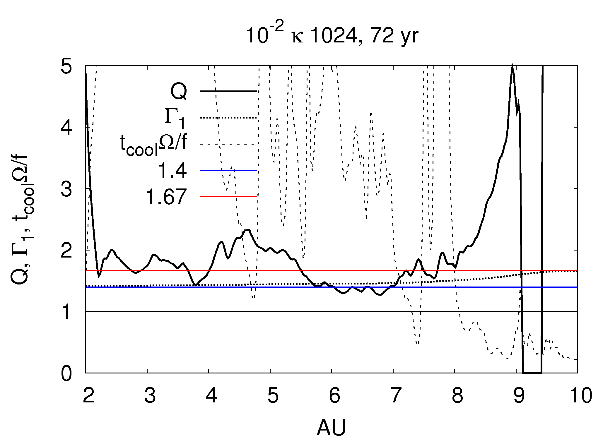
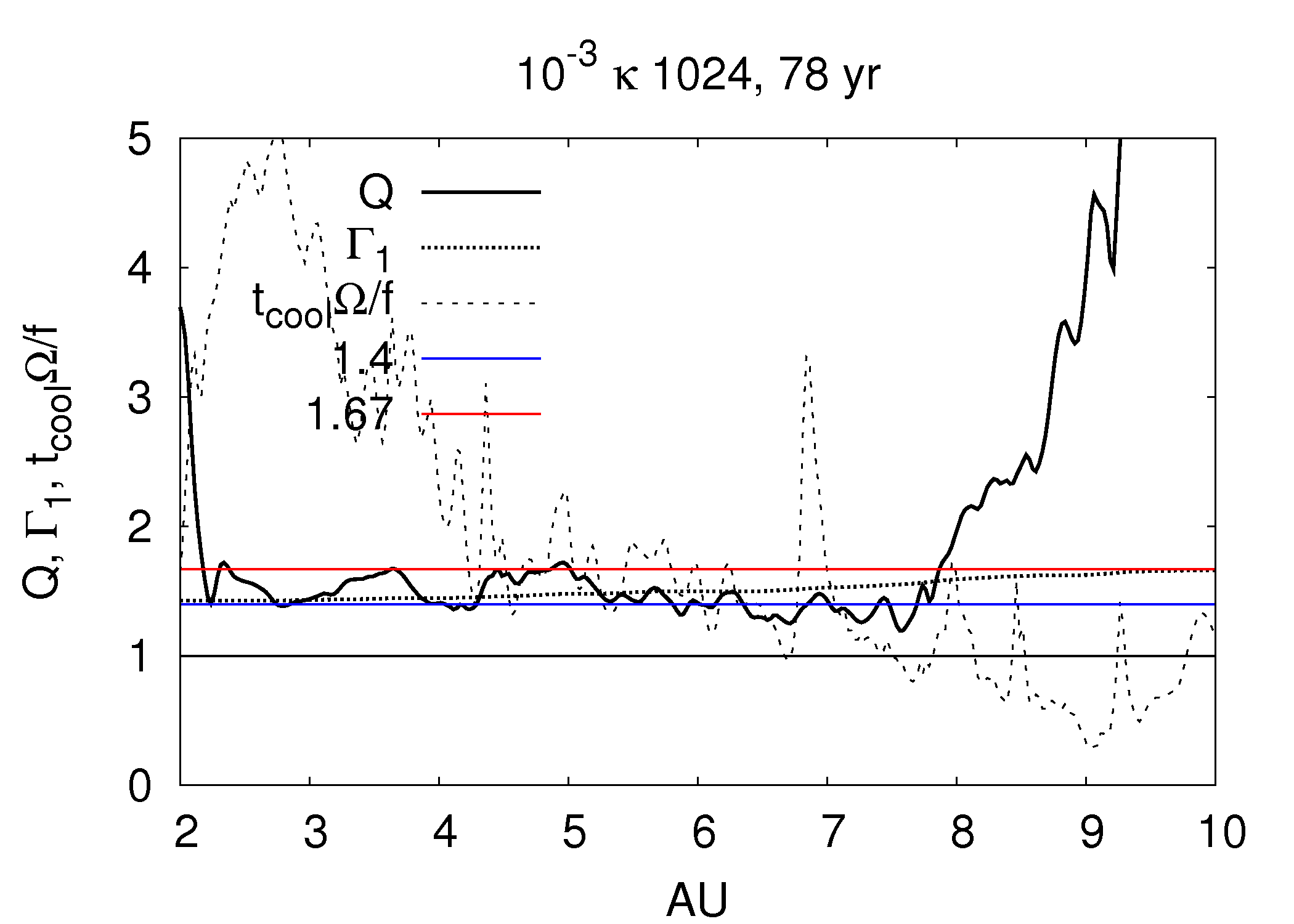
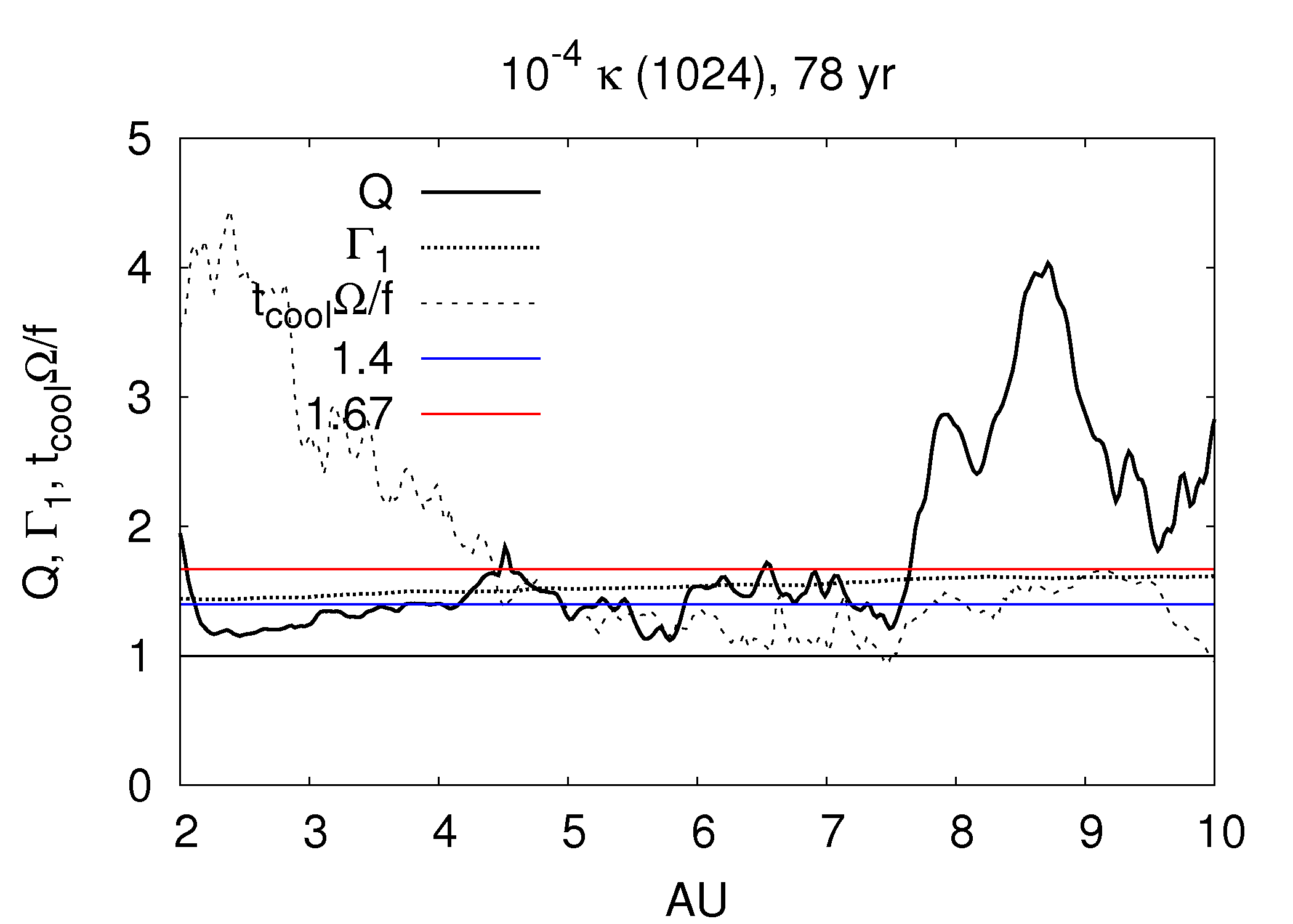
The importance of the opacity for disk cooling is also shown in Figures 13 through 15. On these plots, three quantites are shown: the Toomre , the mass-weighted , and the profiles. For the curves, the cooling times are calculated by dividing the azimuthally and vertically integrated internal energy by the azimuthally and vertically integrated radiative cooling rate for each annulus in the disk. The is the critical value of , below which fragmentation is expected (Gammie 2001), for the corresponding . Rice et al. (2005) demonstrated that and . Based on these values, we assume for the stability analysis presented here. One should keep in mind that is not a strict threshold and that the relation is approximate, especially for simulations that permit the cooling time to evolve with the disk (Johnson & Gammie 2003; Clarke et al. 2008). Regardless, it serves as a general indicator for disk fragmentaiton.
As Figures 13 through 15 demonstrate, the disk is approaching a state of constant for a wide range of radii, as expected in an asymptotic phase (Mejía et al. 2005). The mass-weighted average s between 3 and 6 AU are given in Table 1 and tend to decrease, as expected, when the opacity decreases. They do not seem to be greatly affected by resolution. The variation in the average with opacity is roughly consistent with the measurements. One should keep in mind that the profiles represent snapshots of the disk, while the measurements are time averages. The standard simulation is not shown in the stability plots, but the analysis of the 512 standard disk shows that it is highly stable against fragmentation.
Because the cooling times fluctuate rapidly, we average the integrated cooling rates and the internal energies for the, roughly, 65- and 70/80-year snapshots. The cooling time profiles for the appropriate only drop substantially below unity over extended regions where is high; these disks are stable against fragmentation. As the opacity is lowered, the cooling times decrease as well, with the simulation close to the fragmentation limit. It should also be noted that the only disk that behaves like a constant disk is the standard opacity simulation (not shown), and for all other simulations, a constant is inappropriate (see Boley et al. 2007a).
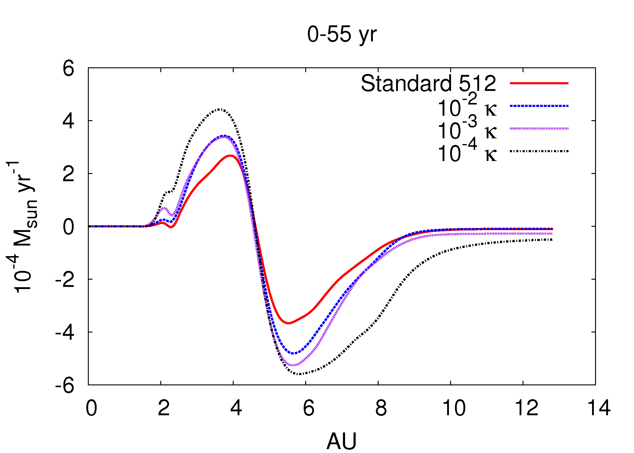
Mass in these disks is redistributed efficiently during the activation of GIs. Time-averaged mass fluxes are calculated by differencing the mass inside a cylinder at two different times. This represents the average mass flux as calculated by the second-order hydrodynamics scheme, and it is independent from the fluid element tracer. The inward and outward accretion rates vary, and in all simulations, can be well above yr-1 (Fig. 16).
4.3 Shocks
Due to our resolution, shocks are spread over scales of about cm or larger, whereas 1D calculations of chondrule-producing shocks give structures cm (Desch & Connolly 2002). To overcome this difficulty, we measure the pressure difference between the pre- and post-shock regions to calculate the Mach number . Using the pressure and temperature histories for each fluid element, a possible shock is identified whenever the changes from negative to positive then back to negative. The pre-shock flow is taken to be the first sign switch, and the post-shock flow is the second sign switch. Let be the fractional pressure change, where and are the pre- and post-shock pressures, respectively, and where is the average of the pre- and post-shock first adiabatic index. If , the event is counted as a shock. Once is determined, the pre-shock velocity is calculated, where is the pre-shock adiabatic sound speed of the gas. The shock strengths are also derived using the ratio of the post-shock to pre-shock temperatures: . Both approaches should give the same answer whenever the shocks are cleanly defined and adiabatic. However, If radiative cooling becomes very efficient, then assuming adiabatic shock conditions may be incorrect. Furthermore, secondary waves or shocks (Boley & Durisen 2006) may make identifying pre- and post-shcok regions very difficult. Neither method is clearly favored, and both will only provide crude estimates.
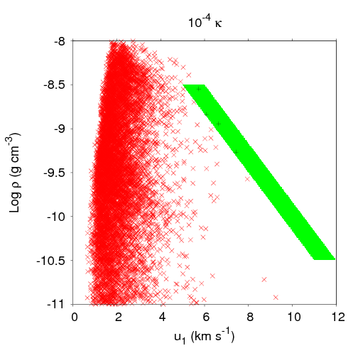
We estimate a shock to be chondrule-forming when lies in a 1 km s-1 band between 5 km s-1 and 11 km s-1 and when the pre-shock density is between = -8.5 and -10.5. This estimate is based on the Desch & Connolly (2002) 1D calculations, similar to the relation used to locate chondrule-producing shocks in Figure 1. Chondrule-forming shocks should be thought of as having the potential to form chondrules, but may not yield chondritic material due to incompatible dust to gas ratios, too high or low cooling rates, and fractionation.
Table 2 indicates shock information as extracted from the pressure histories of the fluid elements. Estimating shock strengths with the temperature ratio yields comparable numbers except for the chondrule-forming shocks (see below). Column two shows approximately the total number of detected shocks (TS) with , and column three displays the average number of shocks per fluid element. Columns four (TS Mass) and five (CS Mass) show the total dust mass (see below) that goes through a shock with and the total dust mass that encounters a chondrule-forming shock, respectively. To estimate how much dust is processed in shocks, we assign each fluid element a mass by calculating the total disk mass within some and distributing that material evenly among all fluid elements in that . A gas to solids ratio of 100 is assumed everywhere for the dust processing calculations. Although this is inconsistent with the growth and settling of solids assumed in six of the simulations, we do not worry about this detail inasmuch as the midplane will process more solids per shock and the high-altitude shocks will process less. Finally, column six shows the total number (Total FE) of fluid elements that remain after the 70 yr time period, i.e., the elements that were not accreted onto the star or fluxed into background density regions.
We check whether the total number of detected shocks is reasonable by evaluating the expected number of shocks in a Keplerian disk with -arm spiral waves. If the corotation radius for the pattern is , the number of shocks during some time period for a fluid element orbiting at is
| (6) |
Evaluating equation (6) for 1000 fluid elements evenly distributed in annuli between 2 and 8 AU, with AU, with , and with yr yields approximately 8000 shocks. So the number of detected shocks in these simulations is reasonable.
The total number of shocks per fluid element are roughly consistent for each simulation except for the runs. The more flocculent spiral structure in these simulations not only produces a larger number of shocks in the disk, but also creates candidate chondrule-producing shocks for four fluid elements; the 1024 simulation has one fluid element that experiences a possible chondrule-forming shock. Several thousand of dust are pushed through shocks in each simulation, implying that almost all dust experiences a shock with . In addition, a few of dust experience chondrule-forming shocks in the runs. We remind the reader that these are only crude, order of magnitude estimates. When the temperature ratio is used, shocks with chondrule-forming strengths are undetected, but the total dust mass pushed through shocks remains the same to about one percent.
5 Discussion and Conclusions
In this section, we review the implications of the results of this study for disk fragmentation, the effects of opacity on disk cooling, the FU Ori phenomenon, and chondrule formation. We remind the reader that the simulations presented here are meant to be a numerical experiment that explores the possible connection between chondrules, FU Ori outbursts, and bursts of GI-activity. Moreover, this experiment provides a systematic study of the effects of opacity on disk cooling, which complements the Cai et al. (2006) metallicity study and provides a test bed for disk fragmentation criteria.
5.1 Fragmentation
After the onset of the burst, none of the disks fragments, and only the 512 simulation shows dense knot formation during the peak of the burst (10-30 yr). These knots do not break from the spiral wave even in the 1024 simulation, and so clump formation does not seem to be missed due to poor resolution. One should also keep in mind that for these simulations, the disk is first relaxed to equilibrium with standard opacity and then the opacity is suddenly dropped by a factor of 104 at . In effect, the dust settling is treated as instantaneous. Knot formation may not occur in a disk with more realistic settling timescales. As discussed below, this is also a caveat for the chondrule formation results. On the other hand, it does suggest that disk fragmentation might occur inside 10 AU under even more extreme, but perhaps unphysical, conditions than we have modeled.
The stability of these disks against fragmentation is supported by Figures 13 through 15. The cooling rates for the standard and simulations are too low to cause disk fragmentation. The and simulations do have areas where , but the disks approach stability against GIs in those regions (; Durisen et al. 2007). As noted in §4.2, is not a strict instability criterion, but it does serve as an estimate for disk stability against fragmentation. For no simulation is well below unity where is also .
Lowering the opacity increases the cooling rates. The simulations exhibit the most rapid cooling because the midplane optical depths are near unity, which results in the most efficient radiative cooling possible. Changes in dust opacity have a profound effect on disk cooling. Although not modeled, if the opacity were to continue to drop such that the midplane optical depth becomes well below unity, cooling would once again become inefficient. In addition, supercooling of the high optical depth disks (standard and ) by convection does not occur. Based on our results, we believe that hydraulic jumps as a result of shock bores (Boley & Durisen 2006) rather than convection are a better explanation for the upwellings around spiral arms reported by Boss (2004a) and Mayer et al. (2007). These findings are consistent with analytic arguments by Rafikov (2005, 2007), with numerical studies of disk fragmentation criteria by Gammie (2001), Johnson & Gammie (2003), and Rice et al. (2005), and with global disk simulations where tests of the radiation algorithm and/or careful monitoring of radiative losses were performed (Nelson et al. 2000; Boley et al. 2006, 2007b; Stamatellos & Whitworth 2008).
The radiative algorithm used in CHYMERA has passed a series of radiative transfer tests that are relevant for disk studies, including permitting convection when expected. Our conclusions regarding fragmentation are based on mulitple analyses: surface density rendering (Figures 4-7), an energy budget analysis (Figures 9 and 10), cooling temperature and brightness maps (Figures 11-12 ), and a cooling time stability analysis (Figures 13-15). It is also important to point out that these results do not contradict Stamatellos et al. (2007) or Krumholz et al. (2007), who find fragmentation in massive, extended disks ( AU).
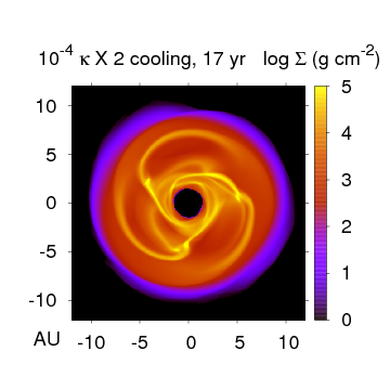
It is also pertinent to demonstrate that the CHYMERA code can detect fragmentation when cooling rates are high and is low. Figure 17 shows a snapshot for a simulation similar to the 512 simulation, but with the divergence of the fluxes artificially increased by a factor of two. In the normal simulation, kinks in the spiral waves form during the onset of the burst. As discussed above, the disk is very close to the fragmentation limit, but the knots do not break from the spiral wave. Figure 15 suggests, although for a later time, that increasing the cooling rates by a factor of two would drop well below unity in low- regions. Figure 17 confirms that the disk fragments with such enhanced cooling. However, we remind the reader that the simulation has the optimal optical depth for cooling (). We cannot imagine any physical process that could cause a factor of two enhancement in cooling.
Three clumps form, one for each spiral wave, between 4 and 5 AU. The location of clump formation is consistent with the prediction by Durisen et al. (2008) that a spiral wave is most susceptible to fragmentation near corotation. One of the clumps survives for several orbits and eventually passes through the inner disk boundary. Resolution is always a concern for simulations. Because these results are consistent with analytic fragmentation limits and numerical fragmentation experiments, we conclude that CHYMERA can detect fragmentation at the resolutions employed for this study.
As discussed above, when the opacity is abruptly decreased by a factor of 104, the disk does approach fragmentation-like behavior. A similar effect is reported by Mayer et al. (2007), who find that their disk only fragments when the mean molecular weight is suddenly switched from to . However, the simulation presented by Boley et al. (2006) was accidentally run with , and Cai et al. (2006, 2008) purposefully ran their simulations at the high for comparison with the Boley et al. results. None of the studies reported disk fragmentation. This may indicate that when a disk approaches fragmentation shortly after a sudden switch in a numerical parameter, e.g., opacity here and in Mayer et al., the fragmentation may be numerically driven rather than physically, especially because sudden changes in cooling rates make disks more susceptible to fragmentation (Clarke et al. 2008). Regardless, the results do indicate that disk fragmentation by GIs may be possible under very extreme conditions. Whether such conditions are physically possible or realistic remains to be shown. Based on our results here and in earlier papers, disk fragmentation for s of AU appears to be a yet-unproven exception rather than the norm.
5.2 FU Ori Outbursts
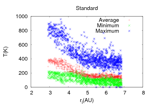
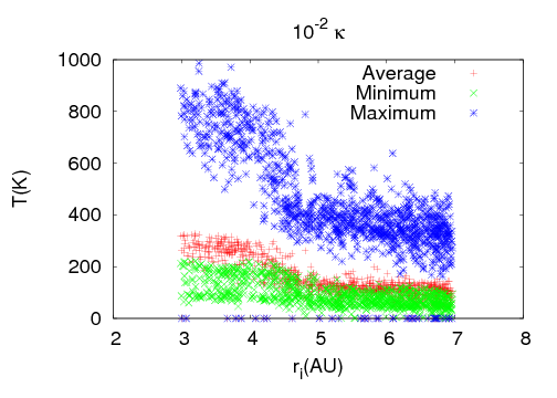
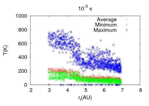
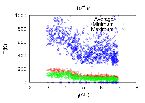
In these simulations, the strong bursts of GI activity provide high mass fluxes ( yr-1, see Fig. 16) throughout each disk. Even though corotation is at AU for the major spiral arms, the 2 AU region of the disk is strongly heated. Fluid elements approach peak temperatures of K in all simulations (Fig. 18). It is not difficult to speculate that if a larger extent of the disk were modeled, the temperatures due to shocks would be large enough to ionize alkalis thermally and possibly sublimate dust (1400-1700 K). If such a condition is met, then an MRI could activate and rapidly carry mass into the innermost regions of the disk. From these simulations it appears to be plausible, but by no means proven, that a burst of GI activity as far out as 4 AU can drive mass into the inner regions of the disk and create strong temperature fluctuations, which may then be responsible for a thermal instablility. Although we are simulating very massive disks, we note that such systems may exist during the Class I YSO phase. Additional studies need to be conducted, preferably with a self-consistent buildup of a dead zone, to address the efficiency of this mechanism in low mass disks.
There are at least three observable signatures for this mechanism. First, if a GI-bursting mass concentration at a few AU ultimately results in an FU Ori phenomenon, then one would expect to see an infrared precursor from the GI burst, with a rise time of approximately tens of years. Second, one would also expect for a large abundance of molecular species, which would normally be frozen on dust grains, to be present in the gas phase during the infrared burst due to shock heating (Hartquist 2007, private communication). Third, approximately the first ten AU of the disk should have large mass flows if the burst takes place near to 5 AU. We speculate based on these results that if the burst were to take place at 1 AU, then high outward mass fluxes should be observable out to a few AU.
5.3 Dust Processing
Each simulation shows that a large fraction of material goes through shocks with . Although these shocks are weak, their abundant numbers may result in the processing of dust to some degree everywhere in the 2-10 AU region. In fact, such processing may be necessary for prepping chondritic precursors for strong-shock survival (Ciesla 2007, private communication).
Based on the arguments presented in §2, the intent was to produce spirals with large pitch angles by constructing a disk biased toward a strong, sudden GI-activation near 5 AU. Even with this bias, the pitch angles of the spirals remain small, with . Why are the pitch angles so small? According to the WKB approximation, (Binney & Tremaine 1987), where is the radial wavenumber for some -arm spiral. The most unstable wavelength for axisymmetric waves (Binney & Tremaine 1987) is roughly for disk scale height . For a disk unstable to nonaxisymmetric modes, corresponds to some -arm spiral (e.g., Durisen et al. 2008). By relating ,
| (7) |
in the linear WKB limit (), where is a factor of order unity that relates to the -arm spiral. Because in gravitationally unstable disks, the linear WKB analysis may be marginally applicable. Equation (7) predicts that linear spiral waves in these disks should have pitch angles to 11∘ for between 1 and 1/2, respectively. It appears that this estimate for extends accurately to the nonlinear regime, a result we did not expect.
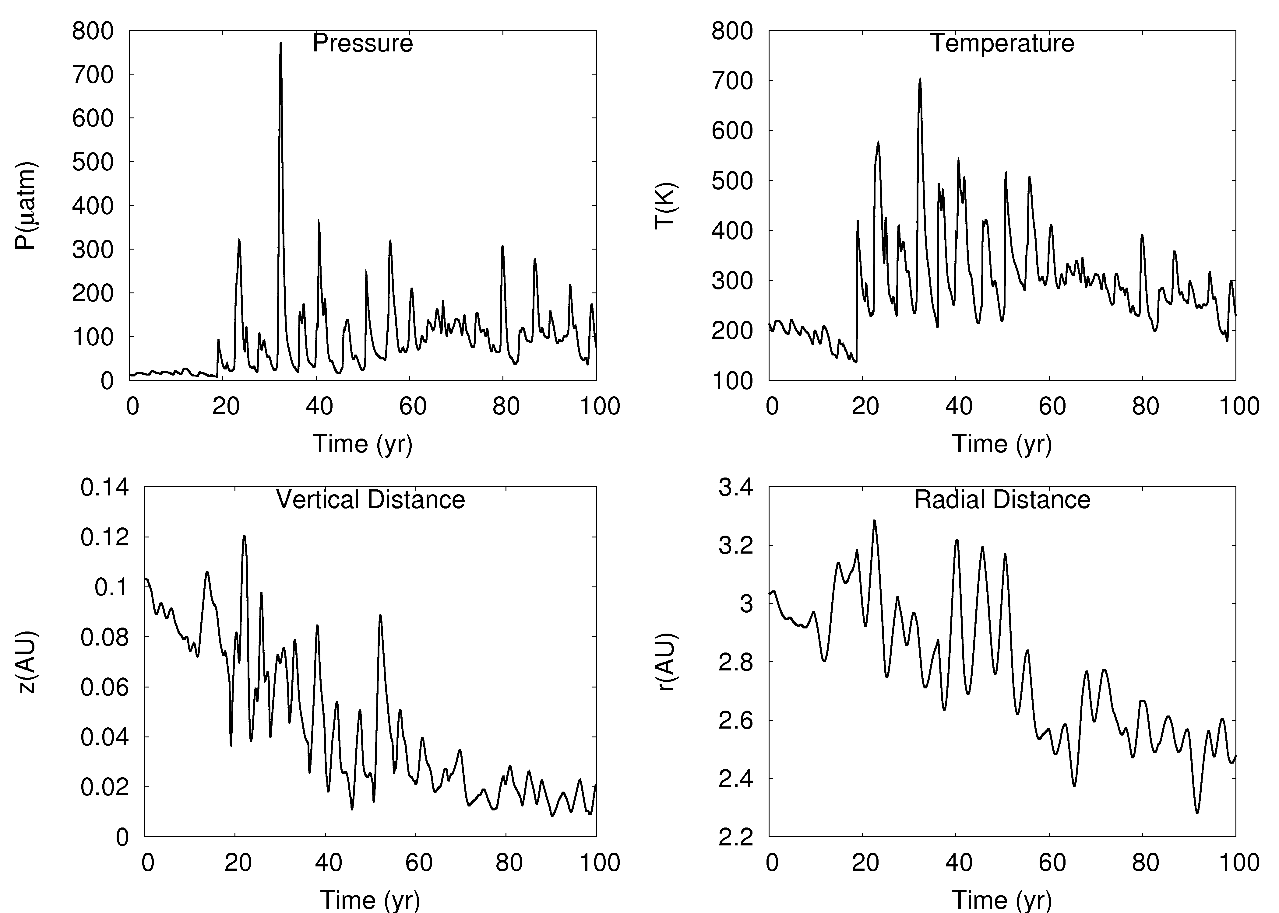
The GI spirals are efficient at heating the disk and transporting angular momentum, but not at producing chondrules. Only for the simulation are multiple candidate chondrule-producing shocks detected, and there is only one chondrule-producing shock in the 1024 simulation. These low opacity disks have relatively flocculent spiral morphologies, including kinks in spiral waves. The simulations are on the verge of fragmentation. When interpreting these results, it is important to remember that the opacities were lowered abruptly and in a quite unphysical way. In addition, these detections are based on the fractional pressure change . If the temperature change is used, no chondrule-producing shocks are detected. This discrepancy may be due to efficient radiative cooling, which may make the assumption of adiabatic shock conditions incorrect, and/or to confusion with additional waves induced by shock bores. For the rest of this section, we assume that the pressure difference is the reliable shock identifier in order to discuss the implications of detecting chondrule-forming shocks in these disks. A thermal and spatial history for a fluid element that experiences a possible chondrule-forming shock is shown in Figure 19.
To estimate the occurrence of a chondrule-forming shock, we employ a generous - criterion (Fig. 20). We do not take into account the optical depth criterion of Miura & Nakamoto (2006) on grounds that the large scale over which these shocks take place can allow for chondrules to equilibrate with their surroundings (Cuzzi & Alexander 2006). However, one should be aware that the optical depth criterion of Miura & Nakamoto will likely exclude all chondrule-producing shocks inside 4 AU in the - plane for these simulations. All candidate chondrule-forming shocks occur between and 5 AU and at altitudes that are roughly less than a third of the gas scale height. Because a large degree of settling is assumed, these shocks are located in regions that may be consistent with the dusty environments in which chondrules formed (Wood 1963; Krot et al. 2005).
We estimate that of dust is processed through chondrule-forming shocks. Because these shocks are limited to the onset of the GI burst, a few of dust would be processed in the disks if they went through about ten outbursts. If more outbursts take place than those that lead to an FU Orionis event, then more chondritic material could be produced. In order to produce these shocks, the disk was pushed toward fragmentation by suddenly dropping the opacity by a factor of . We conclude that for bursts of GIs near 4 or 5 AU to produce chondrules, the disk must be close to fragmentation.
6 The Unified Theory
The hypothesis behind the work summarized here is that bursts of GI activity, dead zones, the FU Ori phenomenon, and chondrule formation are linked. The general picture is that mass builds up in a dead zone due to layered accretion and that GIs erupt once becomes low. This activation of the instability causes a sudden rise in the mass accretion rate that heats up the disk inside 1 AU to temperatures that can sustain thermal ionization and an MRI. The MRI shortly thereafter activates the thermal instability (Bell & Lin. 1994; Armitage et al. 2001; Zhu et al. 2007). In addition, the strong shocks process dust and form chondritic material in the asteroid belt and at comet distances.
Given the results of our simulations, we think the Boss & Durisen conjecture that dead zones bursting at 4-5 AU can produce chondrules is unlikely, unless the disks are on the verge of fragmentation. Because the conditions for fragmentation inside s of AU are very difficulty to achieve, we conclude that this is not viable as a general chondrule-formation mechanism. As a result, we return to Figure 1. Based on our simple, analytic argument in equation (1), chondrule formation can take place in the asteroid belt and at cometary distances for GI-bursting dead zones between about 1 and 3 AU, even with . As suggested by Wood (2005), chondritic parent bodies may be representative of temporal as well as spatial formation differences. Bursts that occur roughly between 1 and 3 AU seem to be able to accommodate this scenario, and could drive the FU Ori phenomenon (Armitage et al. 2001). As the disk evolves, the location of the dead zone can vary, with multiple bursts occurring at a few AU. Accretion rates between and could build up a 0.01 dead zone every to years, respectively. Some of these bursts may drive the FU Ori phenomenon and produce chondrules, but others may only be responsible for chondrule-formation events. In this scenario, the disk need not fragment, and there should be between about 10 and 100 separate chondrule-formation events. Future work is required to ascertain the plausibility of this modified version of the unified theory.
We would like to thank F. Ciesla, S. Desch, and L. Hartmann for fruitful discussions. We would also like to thank the anonymous referee for comments and suggestions that helped improve this manuscript. A.C.B.’s contribution was supported by a NASA GSRP fellowship, and R.H.D.’s contribution was supported by NASA grant NNG05GN11G. This work was supported in part by the IU Astronomy Department IT facilities, by systems made available by the NASA Advanced Supercomputing Division at NASA Ames, by systems obtained by Indiana University through Shared University Research grants through IBM, Inc., to Indiana University, and by dedicated workstations provided to the Astronomy Department by IU’s University Information Technology Services.
References
- Akima (1970) Akima, H. 1970, JACM, 17, 4
- Armitage et al. (2001) Armitage, P. J., Livio, M., & Pringle, J. E. 2001, MNRAS, 324, 705
- Balbus & Hawley (1991) Balbus, S. A. & Hawley, J. F. 1991, ApJ, 376, 214
- Bell & Lin (1994) Bell, K. R., & Lin, D. N. C. 1994, ApJ, 427, 987
- Binney & Tremaine (1987) Binney, J., & Tremaine, S. 1987, Galactic dynamics (Princeton: Princeton Univ. Press, 1987)
- Bizzarro et al. (2004) Bizzarro, M., Baker, J. A., Haack, & H. 2004, Nature, 431, 275
- Boley (2007) Boley, A. C. 2007, Ph.D. Thesis, Indiana University
- Boley & Durisen (2006) Boley, A. C., & Durisen, R. H. 2006, ApJ, 641, 534
- Boley et al. (2005) Boley, A. C., Durisen, R. H., & Pickett, M. K. 2005, in ASP Conf. Ser. 341, Chondrites and the protoplanetary disk, 839
- Boley et al. (2007b) Boley, A. C., Durisen, R. H., Nordlund, Å, & Lord, J. 2007b, ApJ, 665, 1254
- Boley et al. (2007a) Boley, A. C., Hartquist, T. W., Durisen, R. H., & Michael, S. 2007a, ApJ, 656, L89
- Boss (1997) Boss, A. P. 1997, Science, 276, 1836
- Boss (1998) –. 1998, ApJ, 503, 923
- Boss (2001) –. 2001, ApJ, 562, 367
- Boss (2002) –. 2002, ApJ, 567, L149
- Boss (2004a) –. 2004a, ApJ, 610, 456
- Boss (2004b) –. 2004b, ApJ, 616, 1265
- Boss (2005) –. 2005, ApJ, 629, 535
- Boss (2007) –. 2007, ApJ, 661, L73
- Boss (2008) –. 2008, arXiv:0801.4371
- Boss & Durisen (2005) Boss, A. P., & Durisen, R. H. 2005, ApJ, 621, L137
- Cai et al. (2006) Cai, K., Durisen, R. H., Michael, S., Boley, A. C., Mejía, A. C., Pickett, M. K., & D’Alessio, P. 2006, ApJ, 636, L149
- Cai et al. (2008) Cai, K., Durisen, R. H., Boley, A. C., Pickett, M. P., Mejía, A. C. 2007, ApJ, 673, 1138
- Cameron (1978) Cameron, A. G. .W. 1978, M&P, 18, 5
- Ciesla & Hood (2002) Cielsa, F. J., & Hood, L. L. 2002, Icarus, 158, 281
- Clarke et al. (2007) Clarke, C. J., Jarper-Clark, E., & Lodato, G. 2007, MNRAS, 381, 1543
- Cohl & Tohline (1999) Cohl, H. S., & Tohline, J. E. 1999, 527, 86
- Cuzzi & Alexander (2006) Cuzzi, J. N., & Alexander, C. M. O’D. 2006, Nature, 441, 483
- D’Alessio et al. (2001) D’Alessio, P., Calvet, N., & Hartmann, L. 2001, ApJ, 553, 321
- D’Alessio (2006) D’Alessio, P., Calvet, N., Hartmann, L., Franco-Hernández, R., & Servín, H. 2006, ApJ, 638, 314
- Desch (1998) Desch, S. J. 1998, Ph.D. Thesis, University of Illinois at Urbana-Champaign
- Desch (2004) –. 2004, ApJ, 608, 509
- Desch (2007) –. 2007, ApJ, 671, 878
- Desch & Connolly (2002) Desch, S. J., & Connolly, H. C., Jr. 2002, M&PSA, 37, 183
- Durisen et al. (2007) Durisen, R. H., Boss, A., Mayer, L., Nelson, A., Quinn, T., & Rice, K. 2007, in Protostars and Planets V, ed. B. Reipurth, D. Jewitt, & K. Keil (Tucson: Univ. Arizona Press), 607
- Durisen et al. (2008) Durisen, R. H., Hartquist, T. W., & Pickett, M. K. 2008, ApJ, in press
- Durisen et al. (1986) Durisen, R. H., Gingold, R. A., Tohline, J. E., & Boss, A. P. 1986, ApJ, 305, 281
- Fleming & Stone (2003) Fleming, T. P., & Stone, J. M. 2003, ApJ, 585, 908
- Gammie (1996) Gammie, C. F. 1996, ApJ, 457, 355
- Gammie (2001) –. 2001, ApJ, 553, 174
- Green et al. (2006) Green, J. D., Hartmann, L., Calvet, N., Watson, D. M., Ibrahimov, M., Furlan, E., Sargent, B., & Forrest, W. J. 2006, ApJ, 648, 1099
- Harker & Desch (2002) Harker, D. E., & Desch, S. J. 2002, ApJ, 565, 109
- Hartmann (2006) Hartmann, L., D’Alessio, P., Calvet, N., & Muzerolle, J. 2006, ApJ, 648, 484
- Hartmann & Kenyon (1996) Hartmann, L., & Kenyon, S. J. 1996, ARA&A, 34, 207
- Hayashi (1985) Hayashi, C., Nakazawa, K., Nakagawa, Y. 1985, in Protostars and Planets II, ed. D. C. Black, & M. S. Matthews (Tucson: Univ. Arizona Press), 1100
- Iida et al. (2001) Iida, A., Nakamoto, T., Susa, H., & Nakagawa, Y. 2001, Icarus, 153, 430
- Johnson & Gammie (2003) Johnson, B. M., & Gammie, C. F. 2003, ApJ, 597, 131
- Klahr & Bodenheimer (2003) Klahr, H. H., & Bodenheimer, P. 2003, ApJ, 582, 869
- Kley & Lin (1999) Kley, W., & Lin, D. N. C. 1999, ApJ, 518, 833
- Krot et al. (2005) Krot, A. N., Scott, E. R. D., & Reipurth, B. 2005, Chondrites and the Protoplanetary Disk, ASPC Series, 341.
- Krumholz et al. (2007) Krumholz, M. R., Klein, R. I., McKee, C. F., & Bolstad, J. 2007, ApJ, 667, 626
- Krumholz et al. (2007) Krumholz, M. R., Klein, R. I., & McKee, C. F. 2007, ApJ, 656, 959
- Kuiper (1951) Kuiper, G. P. 1951, PNAS, 37, 1
- Levison et al. (2007) Levison, H. F., Morbidelli, A., Van Laerhoven, C., Gomes, R., & Tsiganis, K. 2007, arXiv:0712.0553
- Lynden-Bell & Kalnajs (1972) Lynden-Bell, D., & Kalnajs, A. J. 1972, MNRAS, 157, 1
- Mayer et al. (2007) Mayer, L., Lufkin, G., Quinn, T., & Wadsley, J. 2007, ApJ, 661, 77
- McKeegan et al. (2006) McKeegan, K. D., et al. 2006, Science, 314, 1724
- Mejía (2004) Mejía, A. C. 2004, Ph.D. Thesis, Indiana University
- Mejía et al. (2005) Mejía, A. C., Durisen, R. H., Pickett, M. K., & Cai, K. 2005, ApJ, 619, 1098
- Miura & Nakamoto (2006) Miura, H., & Nakamoto, T. 2006, ApJ, 651, 1272
- Nelson (2006) Nelson, A. F. 2006, MNRAS, 373, 1039
- Nelson et al. (2000) Nelson, A. F., Benz, W., & Ruzmaikina, T. V. 2000, ApJ, 529, 357
- Oishi et al. (2007) Oishi, J. S., Mac Low, M., Menou, K. 2007, arXiv:astro-ph/0702549
- Osorio et al. (2003) Osorio, M., D’Alessio, P., Muzerolle, J., Calvet, N., & Hartmann, L. 2003, ApJ, 586, 1148
- Picket et al. (1998) Pickett, B. K., Cassen, P. M., , Durisen, R. H., & Link, R. P. 1998, ApJ, 504, 468
- Pickett et al. (2000) –. 2000a, ApJ, 529, 1034
- Pickett et al. (2003) Pickett, B. K., Mejía, A. C., Durisen, R. H., Cassen, P. M., Berry, D. K., & Link, R. P. 2003, ApJ, 590, 1060
- Pollack et al. (1994) Pollack, J. B., Hollenbach, D., Beckwith, S., Simonelli, D. P., Roush, T., & Fong, W. 1994, 421, 615
- Press et al. (1986) Press, W. H., Flannery, B. P., & Teukolsky, S. A. 1986, Numerical recipes. The art of scientific computing (Cambridge: University Press)
- Rafikov (2005) Rafikov, R. R. 2005, ApJ, 621, L69
- Rafikov (2007) –. 2007, ApJ, 662, 642
- Rice et al. (2003) Rice, W. K. M, Armitage, P. J., Bate, M. R., & Bonnell, I. A. 2003, MNRAS, 339, 1025
- Rice et al. (2005) Rice, W. K. M, Lodato, G., & Armitage, P. J. 2005, MNRAS, 364, L56
- Roberts et al. (1979) Roberts Jr., W. W., Huntely, J. M., & van Albada, G. D. 1979, ApJ, 233, 67
- Russell et al. (2005) Russell, S. S., Krot, A. N., Huss, G. R., Keil, K., Itoh, S., Yurimoto, H., & Macpherson, G. J. 2005, in ASP Conf. Ser. 341, Chondrites and the protoplanetary disk, 317
- Sano et al. (2000) Sano, T., Miyama, S. M., Umebayashi, T., & Nakano, T. 2000, ApJ, 543, 486
- Stamatellos et al. (2007) Stamatellos, D., Whitworth, A. P., & Ward-Thompson, D. 2007, MNRAS, 379, 1390
- Stamatellos & Whitworth (2008) Stamatellos, D., & Whitworth, A. P. 2008, A&A, in press
- Stepinski (1992) Stepinski, T. F. 1992, Icarus, 97, 130
- Tomley et al. (1991) Tomley, L., Cassen, P., & Steiman-Cameron, T. 1991, ApJ, 382, 530
- Tomley et al. (1994) Tomley, L., Steiman-Cameron, T. Y., Cassen, P. 1994, ApJ, 422, 850
- Toomre (1964) Toomre, A. 1964, ApJ, 139, 1217
- Wood (1963) Wood, J. A. 1963, Icarus, 2, 152
- Wood (1996) –. 1996, Meteoritics Planet. Sci., 31, 641
- Wood (2005) –. 2005, in ASP Conf. Ser. 341, Chondrites and the protoplanetary disk, 953
- Wooden (2005) Wooden, D., Harker, D. E., & Brearley, A. J. 2005, in ASP Conf. Ser. 341, Chondrites and the protoplanetary disk, 774
- Zhu et al. (2007) Zhu, Z., Hartmann, L., Calvet, N., Hernandez, J., Muzerolle, J., & Tannirkulam, A. 2007, ApJ, 669, 483
| Sim. Name | Resolution | Duration | ||
|---|---|---|---|---|
| Adiabatic | 256, 512, 64 | 33 yr | ||
| 512 Standard | 256, 512, 64 | 80 yr | 1.7 | 1.0 |
| 1024 Standard | 512, 1024, 128 | 55 yr | – | |
| 512 | 256, 512, 64 | 110 yr | 1.7 | 1.3 |
| 1024 | 512, 1024, 128 | 110 yr | 1.8 | 1.6 |
| 512 | 256, 512, 64 | 110 yr | 1.5 | 2.1 |
| 1024 | 512, 1024, 128 | 110 yr | 1.5 | 2.2 |
| 512 | 256, 512, 64 | 110 yr | 1.4 | 2.1 |
| 1024 | 512, 1024, 128 | 110 yr | 1.4 | 2.4 |
| Sim. | TS | TS Mass (M⊕) | CS Mass (M⊕) | Total FE | |
|---|---|---|---|---|---|
| 512 standard | 8700 | 9 | 4(3) | 0 | 992 |
| 512 | 8600 | 9 | 4(3) | 0 | 990 |
| 1024 | 9500 | 4(3) | 0 | 962 | |
| 512 | 8300 | 9 | 4(3) | 0 | 978 |
| 1024 | 9500 | 10 | 4(3) | 964 | |
| 512 | 9300 | 10 | 4(3) | 3 | 939 |
| 1024 | 11000 | 12 | 5(3) | 2 | 913 |


