Adaptive Multi-Dimensional Particle In Cell
Abstract
Kinetic Particle In Cell (PIC) methods can extend greatly their range of applicability if implicit time differencing and spatial adaption are used to address the wide range of time and length scales typical of plasmas. For implicit differencing, we refer the reader to our recent summary of the implicit moment PIC method implemented in our CELESTE3D code [G. Lapenta, Phys. Plasmas, 13, 055904 (2006)]. Instead, the present document deals with the issue of PIC spatial adaptation. Adapting a kinetic PIC code requires two tasks: adapting the grid description of the fields and moments and adapting the particle description of the distribution function. Below we address both issues. First, we describe how grid adaptation can be guided by appropriate measures of the local accuracy of the solution. Based on such information, grid adaptation can be obtained by moving grid points from regions of lesser interest to regions of higher interest or by adding and removing points. We discuss both strategies. Second, we describe how to adapt the local number of particles to reach the required statistical variance in the description of the particle population. Finally two typical applications of adaptive PIC are shown: collisionless shocks and charging of small bodies immersed in a plasma.
1 Introduction
Methods to adapt particle-in-cell (PIC) kinetic plasma calculations are very valuable in the study of multiple-length scale problems. Typically, multiple-length scale problems present small regions of stronger gradients embedded in large systems. In such conditions, computational efficiency is achieved best by focusing the attention in the regions of interest.
In PIC methods it is not sufficient to use adaptive grids with finer spacing in the regions of interest, it is also necessary to rezone the number of particles. By particle rezoning we define the operation of increasing the number of particles in regions where higher accuracy is required, and of reducing the number of particles where lower accuracy can be tolerated. Finer grid spacing leads to a better description of the electromagnetic fields, but particle rezoning is needed to gain a better description of the plasma dynamics and a reduction of noise [lapenta94].
Particle rezoning can also be beneficial to keep the load of work uniform on a per cell basis, a feature of crucial interest in a correct load balancing in parallel implementations.
In the present work, we review our work in the field, without attempting to present a complete coverage of the literature. The paper is organizes as follows.
Section 2 reports general comments regarding the task of PIC adaption, discussing in particular the link of particle and grid adaption and the link of both with time differencing. Section 3 deals with grid adaptation, while Section 4 deals with particle adaptation. Section 3 is organized around the two main task of grid adaption: where to adapt and how to adapt. We answer the question of where to adapt by proposing a posteriori measures of the local accuracy. We answer the question of how to adapt by examining two different possibilities: grid motion and grid refinement.
Finally, Section 5 presents to types of simulations where PIC adaption is tested: shocks and dust charging.
2 PIC Code Adaptation
Multiple scale plasma physics problems present two challenging features. First, in any given region of the system processes develop at widely different time scales. Electrons and ions respond with scales made extremely different by their different masses, and a host of different intabilities can develop each with its own time and length scales. Second, different regions of the system can have widely separated spatial and temporal scales. For examples, regions of localized strong gradients can arise locally, as is the case of current sheets in space systems.
The normal textbook approach to PIC is unsuitable to the conditions described above. The standard PIC is based on explicit time differencing and is subject to strict stability constraints. The time step needs to resolve both light-wave propagation and Langmuir wave propagation:
| (1) |
| (2) |
regardless to our relevance to the scale of interest. The grid spacing needs to resolve the electron Debye length:
| (3) |
to avoid the so-called finite grid instability [birdsall]. For this reason explicit methods need to resolve the finest scales everywhere.
When implicit methods are considered [brackbill-forslund], the stability constraints (1, 2, 3) are removed and the local spacing can be chosen according to the required accuracy rather than the need to avoid instability. A practical condition that ensure good energy conservation in an implicit PIC method requires that the average electron population does not travel more than one cell per time step:
| (4) |
This condition can be satisfied if both grid spacing and time step (but not the one only) are chosen large, to step over the small and fast scales. The scales not resolved accurately are not eliminated but rather deformed and the energy present in them is damped like in the physical Landau damping but at an accelerated rate [brackbill-forslund].
We refer the reader to our recent review of the implicit PIC algorithm used in the CELESTE code for the details of how the implicit moment method is derived and used [lapenta05, brackbill-forslund]. In the present paper we describe, instead, how implicit PIC methods can be adapted in space.
To adapt a PIC code to a local scale length, we need to address two issues, how to change the local grid resolution and how to change the local statistical description of the particle distribution functions. The two issues are described in the two sections below. The assumption is made that the host PIC method be implicit, so that large cells do not lead to the finite grid instability described above. Nevertheless, some forms of adaptation can also be of relevance to explicit methods and some of the methods described below can also be used in explicit codes (for example the application in section 5.2 is explicit).
3 Grid Adaptation
Grid adaptation can be achieved by grid refinement (i.e. adding more grid points) in some selected areas or by grid motion (i.e. moving grid points to regions of interest from regions of lesser interest). In the first case, the adaptive mesh refinement (AMR) method [berger] is obtained. In the second case, the moving mesh adaptation (MMA) method [jerrygrid1] is obtained. A specific class of MMA algorithms widely used are ALE methods [hirt]. In all cases we need guidance. We need to know what interesting mean. Often, interest is defined based on the knowledge of the solution.
In many plasma physics problems the regions of interest are readily identified. For example, in space weather simulations localized regions of strong currents are site of topological changes and require a high resolution while regions of smooth flow can be described by coarse meshes.
However, in other instances it is not obvious what regions require increased accuracy. In those cases, we need error detectors to tell us where the error is larger. Here we describe a specific error detector previously applied successfully in plasma physics problems: the operator recovery error origin (OREO) detector [lapentaijnme].
For AMR codes, the OREO detector provides accurate and automatic determination of where the discretization error is being generated. This knowledge is directly used by the AMR method to refine or to coarsen.
For MMA codes, the knowledge of the error needs to be supplemented by a method to move the grid. Given the error what new grid should we use? To answer this additional problem typical of the MMA method we also present a new technique citelapenta based on the Brackbill-Saltzman approach [jerrygrid1].
3.1 Automatic Guidance on Resolution Requirements
In a previous paper [lapentaijnme], we have proposed a new error origin detector based on the extension of the gradient recovery error estimator [ainsworth]. We have named the approach operator recovery error origin (OREO) detector since it extends to any operator the method used for the gradient operator by the gradient recovery error estimator. Below, we summarize briefly the procedure involved in its definition and implementation.
For the sake of definiteness, we shall assume a general N-dimensional grid (where one of the dimensions could be time) where a vector field is node centered. For notation, we label the cells with and the nodes with , using further the notation to indicate the nodes neighboring cell and to indicate the cells neighboring node .
We consider a general multi-dimensional non-linear partial differential operator:
| (5) |
Equation (5) summarizes the most general operator acting on a function defined on the multidimensional space .
Equation (5) is discretized on a grid with nodes :
| (6) |
From the discretized field and from the discretized operator applied to defined only on the grid nodes, it is possible to reconstruct two functions defined everywhere in the continuum space :
| (7) |
where is the b-spline basis function of order for interpolation.
The local truncation error is defined as the difference between the linear interpolation of the discretized operator applied to the discretized field and the exact differential operator applied to the linear interpolation of the discretized field :
| (8) |
The average local truncation error on any given cell is defined as a norm of the error . The norm is often used:
| (9) |
where is the average local truncation error over cell and is the cell volume.
3.2 Moving Mesh Grid Adaptation
We have recently proposed a new approach [lapentagrid] to variational grid adaptation [jerrygrid1] based on the minimization of the local truncation error defined above. The method can be constructed starting from the following equidistribution theorem proven in Ref. [lapentagrid]
theorem: In a optimal grid, defined as a grid that minimizes the local truncation error according to the minimzation principle
| (10) |
the product of the local truncation error in any cell by the cell volume (given by the Jacobian ) is constant:
| (11) |
The equidistribution theorem is applied solving the following Euler-Lagrange equations:
| (12) |
This approach creates a grid where is constant. Note that the equations above are identical to the equations used by the Brackbill-Saltzman variable diffusion method [jerrygrid1]. The primary innovation is that the monitor function is now directly linked with the local truncation error instead of being left undefined. In the typical implementations of the Brackbill-Saltzman method, the monitor function is defined heuristically by the user. The use of the OREO detector proposed here results in a more accurate scheme [lapentagrid].
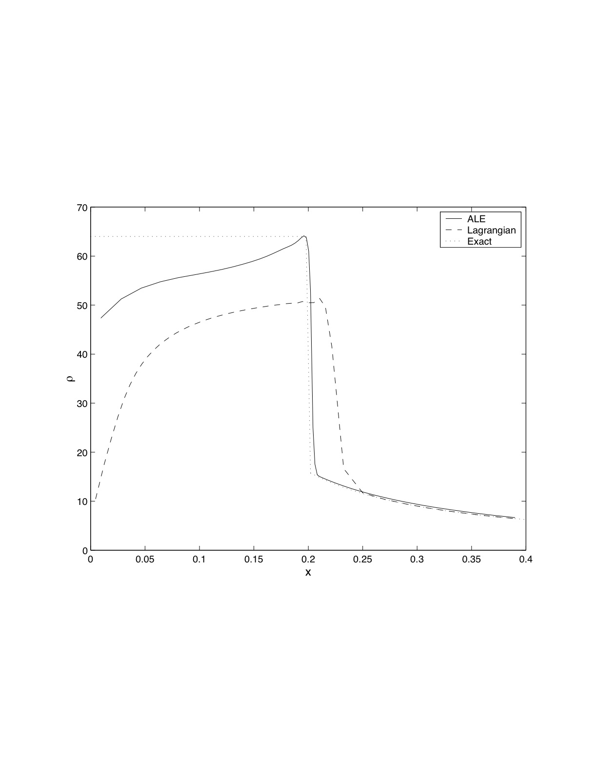
We have applied the grid rezoning described above to our MMA magnetohydrodynamics (MHD) code GRAALE [giannifinn] based on the ALE discretization [hirt]. Here we limit the discussion to the classic spherical 1D implosion test proposed by Noh [noh]. An unmagnetized gas with initially has , and uniform velocity (except in the center where ). The problem represents a serious challenge for Lagrangian calculations and the solution is known to suffer from serious wall heating due to the use of artificial viscosity to capture shocks. Note that we are not using artificial heat conduction [noh] (a tool to mitigate the wall heating problem) precisely to highlight the trouble of Lagrangian calculations for the present case .
The results of an MMA calculation using the adaptive grid is compared with a reference standard Lagrangian calculation. Figure 1 shows the density at the end of the Lagrangian and MMA calculation. The use of adaptive grid results in a much improved solution. The reason for the improvement is explained by the sharper resolution of the shock achieved by the adaptation. As noted in the original paper by Noh [noh], a sharper resolution of the shock also implies a reduction of wall heating, as observed in Fig. 1 for the MMA case.
The use of grid adaptation based on the OREO detector results in an automatic method to increase the accuracy of the MMA method.
3.3 Adaptive Mesh Refinement (AMR)
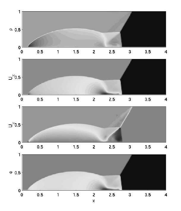
To investigate the performance of the OREO detector in 2D, we have applied it to results obtained with CLAWPACK [leveque]. CLAWPACK is a publicly available software based on an AMR solution [berger] of the conservation laws. We have applied the code to the solution of the gas dynamics equations for the Colella’s wedge problem [colella]. A planar shock is incident on an oblique surface; the angle between the shock direction and the surface is . The actual computed results at time for a 240x120 grid are shown in Fig. 2 where all the expected features [colella] can be recognized.
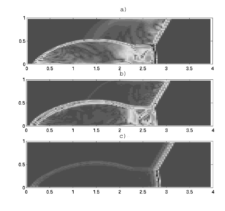
The OREO detector is computed based on the results obtained from CLAWPACK using Algorithm 3. The detector is shown in Fig. 3 for a simulation with a grid 120x60. For comparison we also provide an estimate of the actual error, computed by difference between the solution on a 120x60 grid and the more accurate solution on a 240x120 grid. Clearly the OREO detector is successful in detecting all origins of errors. The shocks are all captured; the slip surface rolling up under the shock is evident. All features are detected.
For reference, Fig. 3-c shows also a similar analysis conducted on another possible candidate for error detection often used in the literature. The detector, which we name warp indicator for convenience, measure the local error as the variance among the different values obtained at a node when extrapolating the internal energy from the four directions (backward and forward along and backward and forward along ). The analysis in Fig. 3-c shows that the two rightmost planar shocks are captured well, while the top and bow shocks are barely visible. All the structure inside the rolling up region within the outer shocks is lost: no slip surface is measured and the internal shock is also lost. In practice the warp indicator is often supplemented by other ad hoc detectors to pick up all shocks, but still the rolling up region and the slip surfaces are often left undetected.
The OREO detector does not miss any feature and can be used reliably alone without any other ad hoc detector.
4 Particle Adaptation
Particle rezoning is needed to increase the number of particles in regions where high accuracy is required, and to reduce the number of particles where lower accuracy can be tolerated. The primary effect of increasing the number of particles is to reduce the variance of the statistical description of the distribution function. In a PIC simulation this increases the accuracy defined as typical in MonteCarlo methods, i.e. as the variance of the simulation.
Particle rezoning must be in effect throughout the calculation to constantly keep the local required accuracy. In multiple-length scale problems, the region of interest can move, and particle rezoning must follow the motion to keep the focus where it is needed. The approach followed here is to use adaptive grids to follow the evolution of the system [jerrygrid1, lapentagrid] and particle rezoning to keep the number of particles per cell constant. This approach leads to finer grid spacing in the region of interest and, automatically, to a higher density of computational particles in that region.
The problem of particle rezoning can be formulated [lapentaadapt] as the replacement of a set of particles with position , velocity , charge , and mass , with a different set of particles with position , velocity , charge , and mass . The criterion for replacement is the equivalence between the two sets, defined as the requirement that the two sets must represent the same physical system, with a different accuracy. This generic definition of equivalence between two sets is given practical bearing by specifying two rules for equivalence.
Two sets of particles are considered equivalent if [lapentaadapt]:
-
1.
the two sets are indistinguishable on the basis of their contributions to the grid moments;
-
2.
the two sets of particles sample the same velocity distribution function.
The first criterion concerns the moments of the particle distribution used to solve the field equations. The moments are defined at the grid points as
| (13) |
where is the assignment function [hockney, bspline]. In general, when nonuniform grids are used, x is the natural coordinate, i.e. the system of coordinates where the spacing between consecutive points is uniform and unitary in all directions [jerrygrid1]. The function F of the particle velocity characterizes the moment. In explicit electrostatic codes, only the charge density is required:
| (14) |
derived from (1) using and using a short notation for . Electromagnetic and implicit codes [vu] require higher order moments like the current density
| (15) |
and the pressure tensor
| (16) |
The first criterion requires the two sets of particles to give the same moments relevant to the field equations. Note that if this criterion is satisfied exactly total energy and momentum are also automatically conserved. The second criterion is more difficult to apply in a quantitative fashion. In previous work [lapenta94, lapentaadapt], it has been proposed to use the test or the Kolmogorov and Smirnov test to verify that the particle distribution is preserved. In practice, this is not easily achieved.
In fluid PIC codes, the first criterion is the only one to be applied, and general schemes for particle rezoning can be derived [lapenta95]. In kinetic PIC codes, the computational particles sample the real plasma velocity distribution, and the second criterion must also be imposed. In the kinetic case the choices are more limited. For this reason, a simpler approach is followed [lapenta94, lapentaadapt]. To increase the number of particles per cell, a given particle is split in two or more new particles displaced in space but all sharing the same speed. The weights and displacements can be chosen to conserve exactly the grid moments, and the velocity distribution is not altered because all the particles have the same velocity.
Another approach can be considered. A particle can be split in the velocity space. The daughter particles have the same position but different velocity. The advantage of this method is that the charge density is not affected. However, the higher order moments (current density and energy) cannot be all preserved. Furthermore, the velocity distribution is altered.
To decrease the number of particles, the splitting operation can be inverted to coalesce two particles into one. The difficulty is that, in general, it is impossible to find two particles with the same velocity. For this reason, particles with different velocity have to be coalesced. To minimize the perturbation of the velocity distribution, the particles to be coalesced must be chosen with similar velocity. An alternative approach is to coalesce three particles into two, which allows one to conserve both energy and momentum [vahedi].
In the following sections, we will provide the two most successful general techniques to adapt the number of particles in a cell. We refer the reader to a previous technical description of the various alternatives and their merits [lapentaadapt]
4.1 Summary of the Algorithms for Particle Rezoning
In the previous sections, we derived all the required blocks to build algorithms to change the number of particles in any given cell. Here, we provide a precise algorithmic description of the methods to increase the number of particles per cell and to decrease the number of particles per cell.
Splitting Algorithm :
Given a cell with particles in a 1D, 2D, or 3D system, any chosen particle (labeled ) with charge (and mass obtained from the charge-to-mass ratio for the species), position (in natural coordinates) and velocity can be replaced by particles, labeled . In 1D, and the new properties are , (where the cell size is unitary), . In 2D, and the new properties are ; , , , ; . In 3D, and the new properties are , , ; , ; ; .
Note that the choice of the particle in the set of particles in the cell is free. In the result sections, we choose the particle with the largest energy: . Algorithm S1 preserves exactly the velocity distribution function and grid moments. However, for quadratic assignment functions the grid moments are only approximately preserved (see Section III).
Coalescence Algorithm:
Given a cell with particles in 1D, 2D, or 3D systems, choose particles close to each other in the phase space. Their properties are , , and . The two chosen particles can be replaced by one particle (labeled ) with , , .
Algorithm C1 preserves the overall charge and momentum and the charge density but perturbs the velocity distribution. Note that one can choose to preserve the energy, but it is not possible to preserve energy and momentum together. The crucial point of algorithm C1 is to choose two particles close in velocity and space. A pair search of the two particles closest in velocity is usually too expensive. For this reason, we perform a diatomic search that sorts the particles into two bins and selects the largest bin. The binning is repeated in sequence for each spatial direction and component of the velocity. The binning is continued until the number of particles in the largest bin is small enough to use a pair search.
5 Examples of Adaptive PIC Simulations
To illustrate the possible applications of adaptive PIC method, below we report two classic cases where uniform PIC calculations show their limitations: collisionless shocks and small scales objects (dust particles) immersed in plasmas.
5.1 Collisionless Shocks
Simulations of collisionless shocks provide a sensitive test of the accuracy of particle rezoning methods [lapenta94]. In the slow shock calculations considered here, a magnetized plasma is flowing toward a piston that reflects the particles. A switch off slow shock is considered, and the component of the magnetic field perpendicular to the normal of the piston is set to zero.
We consider here the same conditions reported in Ref. [lapenta94]. The initial configuration is chosen according to the Rankine-Hugoniot conditions. The initial ratios of the electron and ion pressures to the upstream magnetic field are . The ratio of ion to electron mass is ; the ratio of the upstream ion cyclotron and ion plasma frequencies is , and the shock normal angle, with respect to the magnetic field, is . The size of the simulation region is , and the shock is followed until . Particles are injected at the right boundary to simulate a flowing plasma.
The simulations are performed using CELESTE1D [vu], a 1D implicit PIC code, suitably modified by the author to include particle control.
As a reference, we conduct a reference collisionless shock calculation with a uniform grid and without particle rezoning. The grid has 1000 cells giving a uniform spacing with ; 128 electrons and 128 ions per cell are used. Figure 4 shows the stack plot of as a function of the position at 50 equally spaced time intervals between and .
The reference results are compared with a calculation where particle rezoning is performed using the algorithms described above for splitting and for coalescences. The computation uses an adaptive grid with finer spacing in the shock region () and coarser outside. The region of fine spacing expands in time to follow the motion of the shock. The grid spacing in the region of the shock is kept fixed; and, consequently, the grid spacing in the coarser region grows to keep the number of grid points constant and equal to 300. Figure 4 shows the grid spacing at the end of the simulation, . Note that the area of the shock is well resolved, while the upstream region has large cells. We use the grid jiggling technique of randomly displacing the grid spacing in the large cells to improve the energy conservation of the simulation [jiggling]. This technique results in a random noise added to the grid spacing in the large cells. To avoid any noise in the shock region, the jiggling technique is not used there.
The particles are loaded with a uniform number per cell (the same as before), leading to higher accuracy where the grid is finer. Particle rezoning is required to keep the uniformity of the number of particles per cell as the grid is adapted.
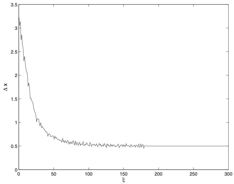
Figure 5 shows the profile of at the end () of the two calculation described above. Clearly, the evolution of the system is calculated correctly. In particular, the shock has traveled backward along the axis for a length of as in the reference case (Fig. 4) and as required by the Rankine-Hugoniot conditions. The results have been validated against previously published results [vushock].

5.2 Charging Of Dust Particles
As a second test, we consider small objects (e.g. dust particles) immersed in a plasma. This condition is common in industrial applications of plasma physics and in space and astrophysical occurrences of dusty plasmas. Dust particles immersed in plasmas tend to acquire a negative charge. The ions and electrons of the plasma reach the surface and stick to it. If no secondary emission or photoemission is present, the equilibrium charge on the dust particle must be negative to repel the more mobile electrons and attract the ions to achieve a balance of electron and ion currents. This problem is of interest in laboratory and in space plasmas [popdust99, prldust95]. We consider here the case where a plasma with an ion to electron temperature ratio and ion to electron mass ratio is drifting relative to a spherical dust particle of radius , where is the electron Debye length. The relative velocity is expressed by the Mach number . The system is simulated using a cylindrical coordinate system with the vertical axis along the direction of the plasma flow and centered in the center of the spherical dust particle. In this configuration, the azimuthal coordinate is invariant, and the problem is 2D axisymmetric.
The interaction of the dust particle with the plasma is described with the immersed boundary method. The application of the immersed boundary method in PIC codes is described in Ref. [sulsky] for fluid problems and in Ref. [lapentaieee] for plasmas. In the present work, we will use the immersed boundary explicit PIC code DEMOCRITUS developed by the author for dusty plasma simulations [popdust99]. A brief description of the method is given below, more details can be found in Ref. [popdust99].
The dust particle is represented by motionless computational particles (object particles) with properties suitable to describe the macroscopic properties of the dust. Dust plasma interface conditions are treated with the immersed boundary method in two steps.
First, we assign to the object particles a susceptibility that can be interpolated to the vertices of the grid to obtain a grid susceptibility:
| (17) |
where are the linear assignment weights. The grid susceptibility is used to alter the Poisson’s equation:
| (18) |
where the potential and the charge density are defined on the cell centers and repeated indexes are summed. The operators and are a difference approximation of the divergence and gradient, respectively. As discussed in detail elsewhere [sulsky, lapentaieee], Eq. (23) is solved everywhere, including in the interior of the dust particle. The term gives an approximation to the correct interface conditions for the electric field. In the present case, is the susceptibility of dielectric dust.
Second, the object particles exert a friction on the plasma particles, via a slowing property that is interpolated to the grid, as in Eq. (22), to produce a grid quantity used to introduce a damping term to the equation of motion of the plasma particles:
| (19) |
The second term in Eq. (24) can be as big as desired to stop the plasma particles on the surface of the dust. The damping term is zero everywhere outside the region occupied by the dust. Equation (23) and Eq. (24) allow one to treat the field and particle boundary conditions on the surface of the dust.
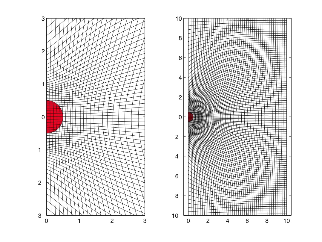
Figure 6 shows the configuration of the grid and of the dust particle for the problem considered here. Note that a nonuniform (but constant in time) grid is used to describe better the sheath around the dust particle. The distance of the dust particle from the boundaries is 10 . The plasma species are initially loaded according to a drifting maxwellian distribution with a downward vertical net flow velocity corresponding to a Mach number . To reach an equilibrium, particles that flow out of the lower boundary are replaced by particles injected at the top boundary [popdust99].
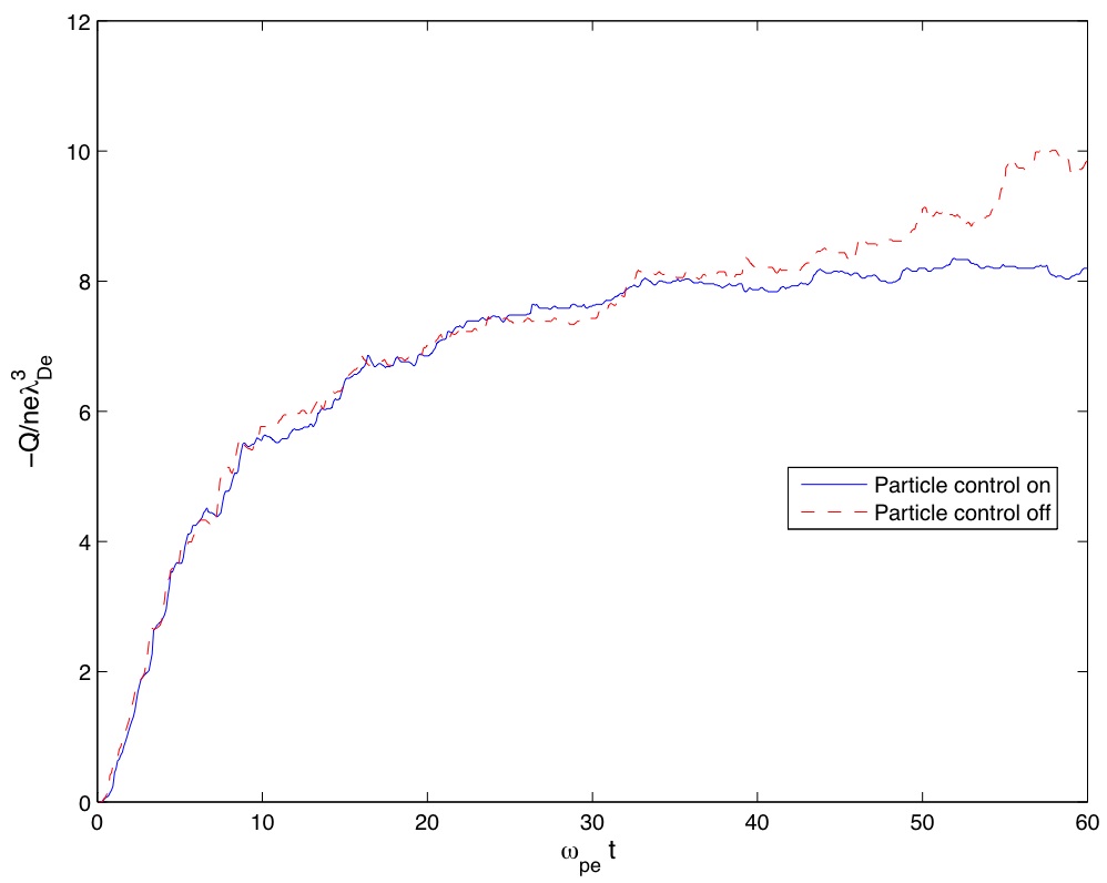
Figure 7 shows the history of the net charge accumulated on the dust particle. In this case, particle rezoning was used to ensure the accuracy of the calculation. The particles are loaded, initially, with a constant number of particles per cell, leading to a higher concentration around the dust particle where the cells are smaller. However, the plasma flow tends to empty the region around the dust reducing the accuracy. Splitting the particles moving toward the dust and coalescing the particles moving away from it is desirable to keep the number of particles per cell and the accuracy constant.
If the calculation is repeated without particle rezoning, the accuracy worsens in time as the region around the dust becomes less populated. Two effects lead to decrease accuracy around the dust particle: the particles originally present are in part captured by the dust and in part just simply flow away according to their average downward velocity of Mach . The new particles that replace them are flowing from regions of larger cells and are less numerous leading to a decrease of accuracy.
As a result of the decrease in accuracy, the dust particle does not reach a steady state in the run without particle rezoning.