Helicity-Protected Domain-Wall Magnetoresistance in Ferromagnetic Weyl Semimetal
Abstract
The magnetotransport properties of disordered ferromagnetic Weyl semimetals are investigated numerically. We found an extraordinarily stable and huge magnetoresistance effect in domain walls of Weyl semimetals. This effect originates from the helicity mismatch of Weyl fermions and is a specific property of Weyl semimetals. Although conventional magnetoresistance effects are strongly suppressed in domain walls where local magnetization varies gradually, the helicity-protected magnetoresistance in Weyl semimetals maintains almost of the magnetoresistance ratio for any kind of thick domain walls, even in the presence of disorder. The contribution of surface Fermi arcs to the magnetoresistance is also discussed.
The magnetoresistance effect has been utilized to read magnetic data in hard disk drives Parkin1995 . Giant magnetoresistance (GMR) occurs in magnetic/nonmagnetic/magnetic trilayer structures because the spins of the conduction electrons lag behind in their orientation with respect to the local magnetization direction, which changes abruptly from one magnetic layer to another. Materials with high spin-polarization (i.e., half-metals) have been searched for with an aim to enhance the magnetoresistance effect Pickett01 .
Domain-wall magnetoresistance is a similar effect that occurs in single magnetic materials with magnetic domain walls Kent01 . Compared to that in trilayer structures, the domain-wall magnetoresistance effect is strongly suppressed as the wall thickness increases because the spatial change of local magnetization is much more gradual in the presence of domain wall structures. However, recent developments in the electronic control of domain walls has renewed interest in electronic transport through domain walls MaekawaBook . In this paper, we propose a novel type of magnetoresistance effect that is not at all suppressed by the thick domain walls (see Fig. 1) in ferromagnetic Weyl semimetals (WSMs) Wan11 ; Burkov11 . Moreover, this magnetoresistance effect is robust against disorder, and is considered to originate from the peculiar transport properties of WSMs: the helicity dependent transport.
Weyl semimetals form a class of topological materials that realize the three-dimensional (3D) Weyl fermion systems near the Weyl nodes. That is, the states near a Weyl node are described by the effective Hamiltonian
| (1) |
The WSMs are typically realized by breaking either the time-reversal or inversion symmetry of Dirac semimetals. Although the WSM materials discovered to date (such as TaAs, TaP, and NbP Huan15 ; Weng15 ; Xu15 ; Souma16 ) are the inversion-broken type, candidates for the time-reversal broken type, i.e., the ferromagnetic WSMs have been proposed recently: magnetic Heusler compounds Hirschberger16 ; Wang16 , compounds with tetragonal structures Jin17 , and Co3Sn2S2 eLiu17 . (Note that antiferromagnetic type WSMs may be realized in Y2Ir2O7 Wan11 , YbMnBi2 Borisenko15 , and Mn3Sn Yang17 ; Ito17 .) The Dirac semimetals arise on the phase boundary between topologically different insulator phases. This bulk gapless region is broadened by breaking one of the symmetries Murakami07 ; Bulmash14 ; Kurebayashi14 , and is transformed into the WSM phase. This means that ferromagnetic WSMs may be achieved by magnetically doping the topological insulators, e.g., Bi2Se3. Such a doped material is essentially inhomogeneous, and thus the effect of disorder must be taken into account.
We employ a simple 3D lattice model for ferromagnetic WSMs based on the Wilson-Dirac type tight-binding Hamiltonian Liu10 ; Ryu12 , which describes the 3D topological insulators on a cubic lattice, and exhibits a Dirac semimetal phase between the topological and ordinary insulating phases. By introducing the exchange coupling term, we obtain the Hamiltonian for magnetic WSMs,
| (2) |
where is the position of lattice sites and () is the lattice vector in the direction. is referred to as “mass” and is the Wilson term. The length unit is set to the lattice constant. and are an anticommuting set of matrices and . We choose the explicit representation of these matrices as and , where and are the Pauli matrices, which correspond to the real- and pseudo-spin degrees of freedom. Therefore, the spin operator is represented as . We introduce an on-site random potential , which is uniformly distributed in . The parameters , , (see Ref. note1, ), and are set so that a single pair of Weyl nodes appears at (see Ref. note2, ). We note that the Weyl nodes should be sufficiently separated for the validity of the discussion below.
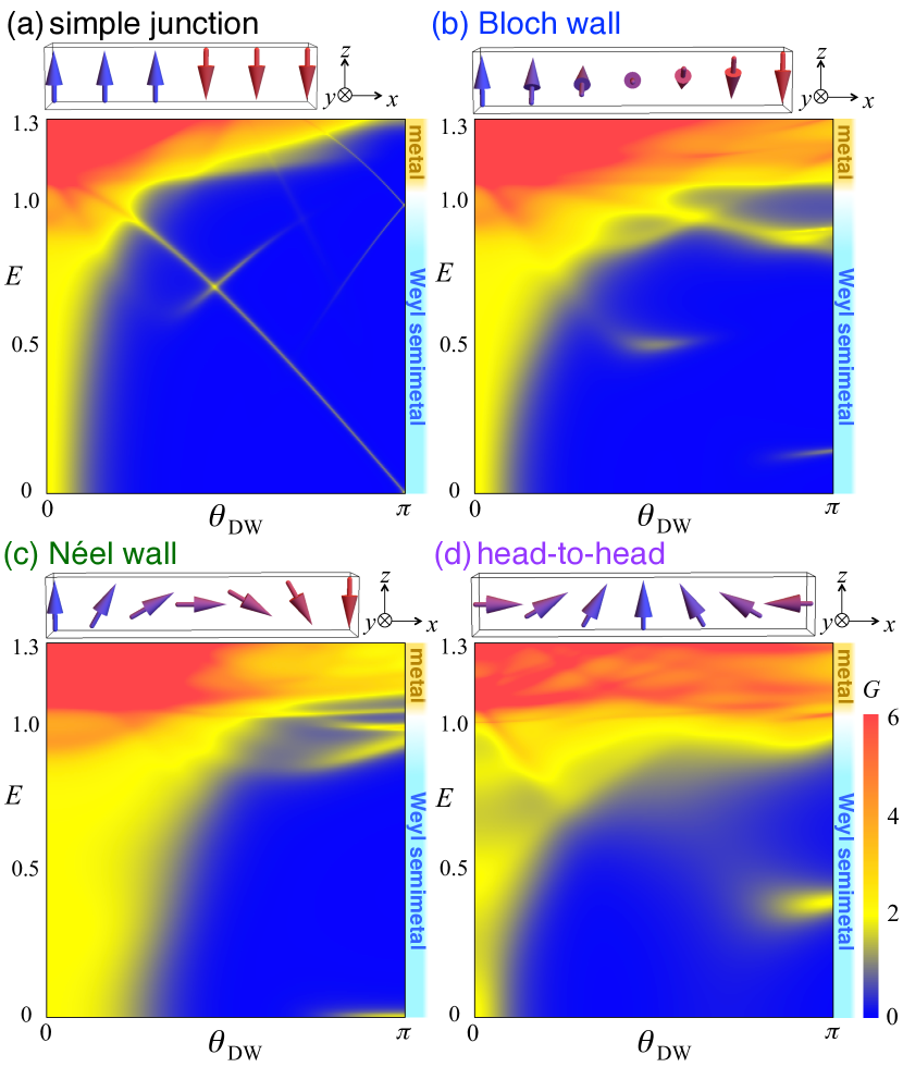
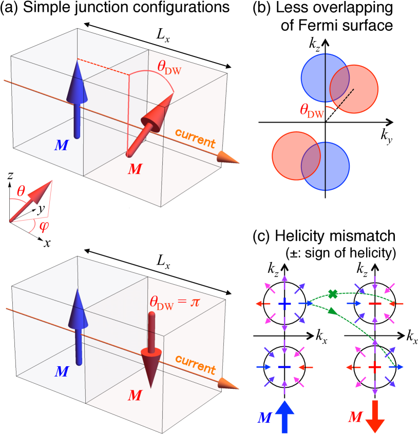
We study the transport through (a) the junction of two magnetic WSMs with different magnetization directions and through three types of domain walls: (b) Bloch, (c) Néel, and (d) head-to-head type (see also schematic magnetic textures in Fig. 1). The direction of the current is set to be the axis. The magnetic structure can be implemented by the -position dependent magnetization [see Fig. 2(a)]. The magnitude of magnetization is assumed to be uniform. Each magnetic structure is achieved with a fixed and -position dependent rotation angle , and these are defined for (a) the simple junction (),
| (3) |
for (b) the Bloch wall (),
| (4) |
for (c) the Néel wall (),
| (5) |
and for (d) the head-to-head wall (),
| (6) |
We consider cubic samples with sites, and numerically calculate the two-terminal conductance between the ideal metallic leads attached to and by using the transfer matrix method Kobayashi13 ; Kobayashi15 and the Landauer formula.
First we focus on the transport in the clean bulk by imposing periodic boundary conditions in the and directions and setting . In a uniformly magnetized system (i.e., ), the transport near the Weyl nodes at energy relies only on the Weyl cones. Hence, in the range ( in Fig. 1), there is only a single pair of conducting channels that correspond to the lowest band () of the Weyl cones and the quantized conductance (in units of ) arises [yellow plateaus on in Figs. 1(a)–(c)]. For the highly doped case ( in this paper), the bulk metallic bands dominate and the feature of WSMs disappears (red regions in Fig. 1).
In the junction system consisting of two magnetic WSMs with different directions of magnetization, the conductance decreases as the relative angle of the magnetizations increases in the low energy region () [Fig. 1(a)]. This significant reduction of transport from to can be understood as less overlapping of the Fermi surfaces Ominato17 ; Nguyen06 . That is, by changing the magnetization direction, the position of the Weyl points and the Fermi surfaces enclosing them shifts from the original position [Figs. 2(a) and 2(b)]. As a result, the overlapping area of the projected Fermi surfaces of the two WSMs (i.e., number of current carrying states) decreases. On the other hand, this simple picture cannot explain the conductance behavior around ; the conductance remains strongly suppressed, even though the Fermi surfaces are again completely overlapped at [Figs. 2(a) and 2(c)]. This implies that the current is almost perfectly reflected at the interface of the WSM with antiparallel magnetizations due to an unconventional reason: the helicity mismatch of the Weyl electrons. The Weyl fermion state characterized by the Hamiltonian Eq. (1) is an eigenstate of the helicity operator . The sign of the helicity is locked around a Weyl node and opposite to that for the partner Weyl29 ; Balents11 [illustrated in Fig. 2(c)]. For an antiparallel junction, the helicities of the Weyl electrons in the overlapping Fermi surfaces are opposite and current cannot pass through the junction.
We next investigate how the type of domain walls affects the transport. The conductance maps in Fig. 1 show that the qualitative behavior in a system with domain walls (b)–(d) is the same as that in (a) the simple junction; the conductance decreases as increases and vanishes at . We note that the thickness of the wall does not play an essential role for (b) Bloch and (c) Néel walls, where the thin-wall limit corresponds to the (a) simple junction. In these domain walls, the combined effect of the helicity mismatch and less overlapping suppresses the transport sup2 , and the conductance remains vanishing for any wall thickness. In contrast, for (d) the head-to-head wall, the system is conducting in the thin-wall limit, where the helicity mismatch does not work. However, the conductance decays exponentially as the thickness of the wall increases because the less overlapping mechanism works in a thick domain wall. As a result, a huge resistance arises in a thick domain wall between antiparallelly magnetized domains, irrespective of the details of the magnetic texture.
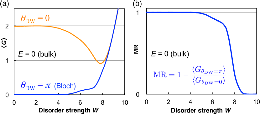
Then we discuss the effect of disorder on the transport. Figure 3(a) shows the conductance near the Weyl nodes () for uniform magnetization () and antiparallel configuration with a Bloch wall (). The transport in WSMs is robust against disorder, so that the conductance for uniform magnetization shows a well-quantized plateau, even in the presence of disorder. As the disorder strength increases further, the plateau breaks down due to inter-node scattering Kobayashi13 . The conductance for the antiparallel configuration remains suppressed up to a certain strength of disorder (), and increases as the disorder strength increases further. The difference of the conductance between the parallel and antiparallel cases disappears at strong disorder () where the system goes into the diffusive metallic phase from the WSM phase Kobayashi14 ; Liu16 . To characterize the magnitude of the magnetoresistance effect, we introduce the magnetoresistance ratio (MR), which is defined as
| MR | (7) |
where represents an ensemble average. Using this quantity, we replotted the data in Fig. 3(b). At weak disorder (), the MR remains at almost . This shows that the magnetoresistance effect is stable even in the presence of weak disorder. At strong disorder (), say, in the diffusive metallic phase, the MR vanishes. Although this upper bound of disorder strength is dependent on the Fermi energy , the qualitative behavior is the same for .
Now we compare this magnetoresistance effect in WSMs with the conventional effect in highly spin-polarized metals, i.e., the magnetoresistance due to spin mistracking. The latter is also demonstrated in our model Hamiltonian Eq. (2) when the Fermi level is near the band edge. To observe this, we calculate the spin-projected density of states, and , with uniform magnetization in the direction [see Fig. 4(a)], using the kernel polynomial method Weisse06 . Plotting the spin polarization as in Fig. 4(b), it becomes clear that an almost perfectly polarized half-metal state is obtained near the upper band edge (). Therefore, just by changing the Fermi energy, we can compare the WSM and the ideal half-metal within the same model.
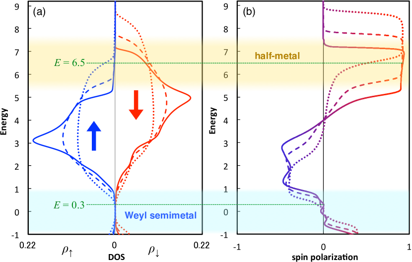
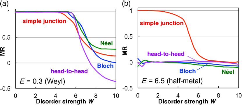
Figure 5 shows the MR (a) in WSMs () and (b) in ideal half-metals () with various types of domain walls. At weak disorder, the MR in a WSM is almost for any type of domain wall. In contrast, the MR in a half-metal with a domain wall is significantly suppressed, while that for an antiparallel junction is almost as that in WSMs. This is one of the most important results in this work. In conventional half-metals with sufficiently thick (more than four lattice sites in this case) domain walls, the spins of conduction electrons can track the direction of local magnetization along the domain walls, and thus the domain-wall magnetoresistance becomes negligibly small. On the other hand, in the WSM phase, the Weyl fermions in the and nodes behave independently, and the helicity is conserved [see Fig. 2(c)], as long as the inter-node scattering is negligibly weak note3 . The domain walls do not induce inter-node scattering in principle, and thus the helicity mismatch nature leads to the perfect magnetoresistance, , even in the presence of the (Bloch or Néel type) domain walls. (Note that in the head-to-head wall case, the magnetoresistance comes from the less-overlapping of the Fermi surfaces.) Another important point is the robustness against disorder. The MR in a half-metal gradually decreases as disorder increases, while that in a WSM remains unity at weak disorder and abruptly decays near the WSM/metal transition point.
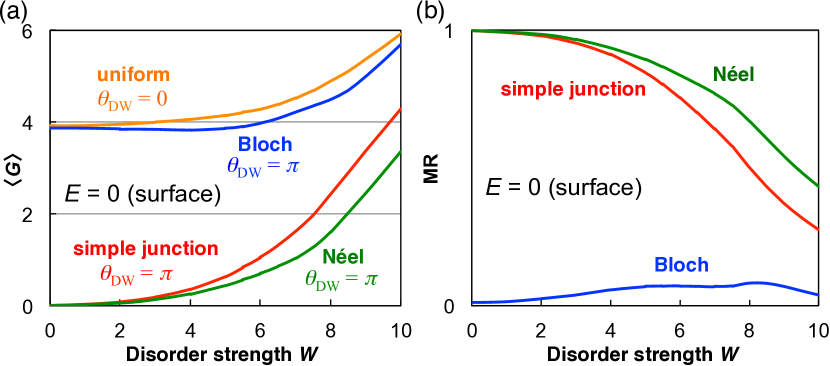
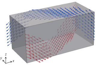
Before concluding, we discuss the contribution of the surface, i.e., Fermi arcs. When the system has surfaces, almost gapless states appear on the surfaces parallel to the magnetization, while the finite-size gap opens in the bulk. Therefore, the surface contribution becomes important for small samples. In our mesoscopic samples with surfaces, the low-energy () transport relies mostly on the surface states. On the surface, the spin of the conducting state is locked with respect to the direction of magnetization and momentum Lv15 . As a result, in a simple antiparallel junction, the current on the surface is completely reflected and yields huge MR (see Fig. 6), as in the case of the bulk. However, with a Bloch domain wall, the conductance recovers and MR becomes small because spiral surface states run through the system (Fig. 7). Therefore, the huge MR is achieved in the presence of surface states, while only in the case of Bloch wall it may be suppressed as the contribution of surface states to transport increases. The surface magnetoresistance effect is not as robust against disorder as that for the bulk. This is considered to be due to the sensitivity of the surface spin-locking to disorder.
We have studied the transport in disordered magnetic WSMs and found a novel type of magnetoresistance effect that arises due to the helicity mismatch. Considering domain walls, we have shown that huge (almost ) MR is achieved, irrespective of the detail of the magnetization configuration. This is a particular feature of WSMs and is in good contrast with conventional domain-wall magnetoresistance due to spin mistracking, which is significantly suppressed by the introduction of a domain wall. We have studied the quantum transport in Weyl semimetals, and the MR will be obtained in mesoscopic systems at low temperatures. Although we have shown the data for small system sizes and the amplitude of the conductance in WSMs is of the order of , the effect can be seen in larger system sizes sup1 . We note that the resistance effect occurs at the interface of two domains with antiparallel magnetizations, and the required condition is sufficiently long coherence length compared with the domain wall thickness (not with the device size). While the resistance from less-overlapping is expected to be observed in ordinary ferromagnetic semiconductors Nguyen06 , it will be more prominent in WSMs due to the strong anisotropy of Fermi surfaces and robustness against disorder. The resistance from helicity-mismatch is a specific quantum transport phenomena for magnetic Weyl semimetals and will become important for spintronics devices. We also emphasize that the effect can be seen in a broad range of energy (i.e., it is not a singularity on the Weyl point ), and it does not require a fine-tuning of chemical potential to observe. We have also shown the robustness of the novel magnetoresistance effect against disorder. This robustness can be observed not only for non-magnetic potential disorder discussed here, but also for magnetic disorder sup3 . These impurity and interface-roughness tolerant features should be advantageous for the manufacture of spintronics devices. Therefore, we propose that the magnetoresistance effect in ferromagnetic WSMs is more promising than the conventional GMR in ideal half-metals.
Acknowledgements.
This work was supported by KAKENHI Grants-in-Aid (Nos. JP15H05854, JP16J01981, and JP17K05485) from the Japan Society for the Promotion of Science (JSPS).References
- (1) S. S. P. Parkin, Annu. Rev. Mater. Sci. 25, 357 (1995).
- (2) W. E. Pickett and J. S. Moodera, Phys. Today 54, 39 (2001).
- (3) A. D. Kent, J. Yu, U. Rüdiger, and S. S. P. Parkin, J. Phys.: Condens. Matter 13, R461 (2001).
- (4) S. Maekawa, S. O. Valenzuela and E. Saitoh, and T. Kimura, Spin Current (Semiconductor Science and Technology) (Oxford University Press, 2012).
- (5) (Supplemental material) The lattice size dependence of the small peak structures is provided online. See Sec. S1.
- (6) X. Wan, A. M. Turner, A. Vishwanath, and S. Y. Savrasov, Phys. Rev. B 83, 205101 (2011).
- (7) A. A. Burkov and L. Balents, Phys. Rev. Lett. 107, 127205 (2011).
- (8) S.-M. Huang, S.-Y. Xu, I. Belopolski, C.-C. Lee, G. Chang, B. Wang, N. Alidoust, G. Bian, M. Neupane, C. Zhang, S. Jia, A. Bansil, H. Lin, and M. Z. Hasan, Nat. Commun. 6, 7373 (2015).
- (9) H. Weng, C. Fang, Z. Fang, B. A. Bernevig, and X. Dai, Phys. Rev. X 5, 011029 (2015).
- (10) S.-Y. Xu, I. Belopolski, N. Alidoust, M. Neupane, G. Bian, C. Zhang, R. Sankar, G. Chang, Z. Yuan, C.-C. Lee, S.-M. Huang, H. Zheng, J. Ma, D. S. Sanchez, B. Wang, A. Bansil, F. Chou, P. P. Shibayev, H. Lin, S. Jia, and M. Z. Hasan, Science 349, 613 (2015).
- (11) S. Souma, Z. Wang, H. Kotaka, T. Sato, K. Nakayama, Y. Tanaka, H. Kimizuka, T. Takahashi, K. Yamauchi, T. Oguchi, K. Segawa, and Y. Ando, Phys. Rev. B 93, 161112 (2016).
- (12) M. Hirschberger, S. Kushwaha, Z. Wang, Q. Gibson, S. Liang, C. A. Belvin, B. A. Bernevig, R. J. Cava, and N. P. Ong, Nat. Mater. 15, 1161 (2016).
- (13) Z. Wang, M. G. Vergniory, S. Kushwaha, M. Hirschberger, E. V. Chulkov, A. Ernst, N. P. Ong, R. J. Cava, and B. A. Bernevig, Phys. Rev. Lett. 117, 236401 (2016).
- (14) Y. J. Jin, R. Wang, Z. J. Chen, J. Z. Zhao, Y. J. Zhao, and H. Xu, Phys. Rev. B 96, 201102 (2017).
- (15) E. Liu, Y. Sun, L. Müechler, A. Sun, L. Jiao, J. Kroder, V. Süß, H. Borrmann, W. Wang, W. Schnelle, S. Wirth, S. T. B. Goennenwein, and C. Felser, arXiv:1712.06722 (2017).
- (16) S. Borisenko, D. Evtushinsky, Q. Gibson, A. Yaresko, T. Kim, and M. N. Ali, arXiv:1507.04847 (2015).
- (17) H. Yang, Y. Sun, Y. Zhang, W.-J. Shi, S. S. P. Parkin, and B. Yan, New J. Phys. 19, 015008 (2017).
- (18) N. Ito and K. Nomura, J. Phys. Soc. Jpn. 86, 063703 (2017).
- (19) S. Murakami, New J. Phys. 9, 356 (2007).
- (20) D. Bulmash, C.-X. Liu, and X.-L. Qi, Phys. Rev. B 89, 081106 (2014).
- (21) D. Kurebayashi and K. Nomura, J. Phys. Soc. Jpn. 83, 063709 (2014).
- (22) C.-X. Liu, X.-L. Qi, H. J. Zhang, X. Dai, Z. Fang, and S.-C. Zhang, Phys. Rev. B 82, 045122 (2010).
- (23) S. Ryu and K. Nomura, Phys. Rev. B 85, 155138 (2012).
- (24) When introducing disorder, the renormalization of mass must be taken into account Groth09 ; Yamakage11 ; Kobayashi13 . In this paper, we tune the mass for a finite disorder strength so that the renormalized mass , and the Dirac semimetal line (i.e., the phase boundary of strong topological insulator/ordinary insulator) in the phase diagram in Ref. Kobayashi13, is then traced.
-
(25)
Assuming the magnetization
is uniform and oriented in the direction, a pair of Weyl nodes appears at ,
if has a real solution. - (26) K. Kobayashi, T. Ohtsuki, and K.-I. Imura, Phys. Rev. Lett. 110, 236803 (2013).
- (27) K. Kobayashi, Y. Yoshimura, K.-I. Imura, and T. Ohtsuki, Phys. Rev. B 92, 235407 (2015).
- (28) Y. Ominato, K. Kobayashi, and K. Nomura, Phys. Rev. B 95, 085308 (2017).
- (29) A. K. Nguyen, R. V. Shchelushkin, and A. Brataas, Phys. Rev. Lett. 97, 136603 (2006).
- (30) H. Weyl, Z. Phys. 56, 330 (1929).
- (31) L. Balents, Physics 4, 36 (2011).
- (32) (Supplemental material) The thickness dependence of the magnetoresistance effect is provided online. See Secs. S2 and S3.
- (33) K. Kobayashi, T. Ohtsuki, K.-I. Imura, and I. F. Herbut, Phys. Rev. Lett. 112, 016402 (2014).
- (34) S. Liu, T. Ohtsuki, and R. Shindou, Phys. Rev. Lett. 116, 066401 (2016).
- (35) A. Weiße, G. Wellein, A. Alvermann, and H. Fehske, Rev. Mod. Phys. 78, 275 (2006).
- (36) In the continuum model, this results from the conservation of the chiral charge , where is the number of Weyl electrons with helicity cxLiu13 .
- (37) B. Q. Lv, S. Muff, T. Qian, Z. D. Song, S. M. Nie, N. Xu, P. Richard, C. E. Matt, N. C. Plumb, L. X. Zhao, G. F. Chen, Z. Fang, X. Dai, J. H. Dil, J. Mesot, M. Shi, H. M. Weng, and H. Ding, Phys. Rev. Lett. 115, 217601 (2015).
- (38) (Supplemental material) The magnetoresistance effect for the magnetic disorder is provided online. See Sec. S4.
- (39) C. W. Groth, M. Wimmer, A. R. Akhmerov, J. Tworzydło, and C. W. J. Beenakker, Phys. Rev. Lett. 103, 196805 (2009).
- (40) A. Yamakage, K. Nomura, K.-I. Imura, and Y. Kuramoto, J. Phys. Soc. Jpn. 80, 053703 (2011).
- (41) C.-X. Liu, P. Ye, and X.-L. Qi, Phys. Rev. B 87, 235306 (2013).
![[Uncaptioned image]](/html/1802.04536/assets/x8.png)
![[Uncaptioned image]](/html/1802.04536/assets/x9.png)
![[Uncaptioned image]](/html/1802.04536/assets/x10.png)
![[Uncaptioned image]](/html/1802.04536/assets/x11.png)