Transport properties in network models with perfectly conducting channels
Abstract
We study the transport properties of disordered electron systems that contain perfectly conducting channels. Two quantum network models that belong to different universality classes, unitary and symplectic, are simulated numerically. The perfectly conducting channel in the unitary class can be realized in zigzag graphene nano-ribbons and that in the symplectic class is known to appear in metallic carbon nanotubes. The existence of a perfectly conducting channel leads to novel conductance distribution functions and a shortening of the conductance decay length.
1 Introduction
The Chalker-Coddington network model [1, 2] (C-C model) is one of the most useful models for describing quantum transport in disordered two-dimensional (2D) electron systems in strong perpendicular magnetic fields. The C-C model can be extended to describe a system with one perfectly conducting channel (PCC) [3]. The PCC is a channel whose transmission eigenvalue is one, regardless of the phase of the system. The PCC in a strong magnetic field can be realized in zigzag graphene nano-ribbons [4].
Although the original C-C model belongs to the unitary universality class, it is possible to construct network models that belong to the symplectic class [5]. The symplectic network model can also be extended to have a PCC of a Kramers doublet. The PCC in the symplectic class appears in metallic carbon nanotubes [6].
In this paper, we study how a PCC affects the transport properties in the unitary and symplectic class. Though the models and origins of the PCC are completely different for these two cases, we show that the effects of the PCC are similar.
2 Models
Transport in a network model is described by a scattering matrix ,
| (1) |
where denotes the incoming/outgoing current amplitude on the left/right terminal of the network. The dimensionless conductance is given by
| (2) |
We have calculated using the method described in Ref. [2].
2.1 Network model with PCC in the unitary class
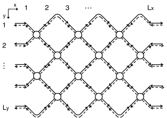
The unitary network model with a PCC (Figure 2) is constructed by adding one extra channel to the original C-C model. The new model has channels ( right-directed and left-directed channels). In the unitary case, a PCC arises from the imbalance in the number of the incoming and outgoing channels [3, 7], leading to a rectangular reflection matrix.

2.2 Network model with a PCC of a Kramers doublet in the symplectic class
The symplectic network model with a PCC (Figure 2) is constructed by adding one extra channel of a Kramers doublet (i.e., two extra channels of up and down spins moving in opposite directions) to the symplectic network model proposed in Ref. [5]. The new model has channels ( right-directed and left-directed channels). In this case, the reflection matrix is an antisymmetric square matrix with odd dimensions. This gives rise to the PCC [6].
In all cases, we have imposed the fixed boundary conditions (FBC) in the transverse direction.
3 Results
3.1 Critical conductance in 2D systems
Conductance distributions in disordered electron systems are universal at the Anderson transition points. In the 2D unitary class, the network has one transition point at the integer quantum Hall transition, irrespective of the existence of the PCC (number of the PCC ). In the symplectic class, the network without a PCC (with FBC) has two types of transitions [8], the metal-insulator and metal-insulator with two Kramers pairs of edge states (i.e. topological insulator) transition. In this paper, we are not concerned with the latter. On the other hand, the symplectic network with a PCC has only the metal-insulator with one Kramers pair of edge states transition [8].
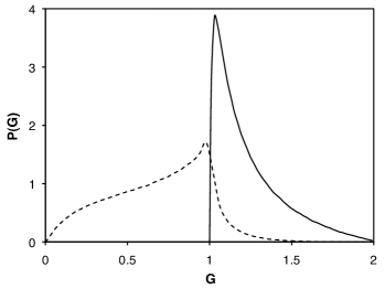
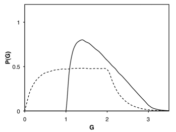
The conductance distribution functions calculated for the unitary and the symplectic class in the square geometry are shown in Figures 4 and 4, respectively. The ensemble averaged conductance and its variance at criticality are listed in Table 1. Since the PCC raises the minimum conductance to one, the conductance for the network models with a PCC is always larger than one. The distribution for network models with a PCC differs completely from that for networks without a PCC. For systems with a PCC, the conductance distribution rises sharply from . We also see that the variances for both models are reduced almost by one half when the PCC is added. Note that the distribution for the models with the PCC is still universal.
| \bruniversality class | |||
|---|---|---|---|
| \mrunitary | 1 | 1.23 | 0.043 |
| unitary | 0 | 0.69 | 0.087 |
| symplectic | 1 | 1.81 | 0.24 |
| symplectic | 0 | 1.27 | 0.43 |
| \br |
3.2 Decay of conductance in the quasi-one dimensional (Q1D) quantum wire
Though the PCC enhances the conductance, the transmission eigenvalue ‘1’ of the PCC repels other transmission eigenvalues [9]. In other words, the PCC makes the length scale of the conductance decay in a quantum wire shorter.
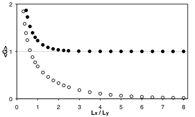
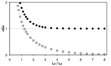
Figures 6 and 6 show the dependence on the longitudinal system length of the conductances calculated for the unitary and the symplectic network models, respectively. Since the parameters controlling the phases for both models are the same as in the previous section, the conductances at in these figures are consistent with in Table 1. Because of the metallic property of the PCC, in Q1D limit , the average conductance with a PCC is , while that without a PCC is . In both classes, the conductance decay length , defined via
| (3) |
of a network with a PCC is shorter than that of a network without a PCC (Table 2).
| \bruniversality class | decay length | |
|---|---|---|
| \mr unitary | 1 | 1.1 |
| unitary | 0 | 3.2 |
| symplectic | 1 | 1.5 |
| symplectic | 0 | 4.0 |
| \br |
4 Conclusion
In summary, we have studied the transport properties of unitary and symplectic networks with one perfectly conducting channel. The system with a PCC has a peculiar critical conductance distribution in 2D. Even in the quasi-1D limit, the system remains metallic. The PCC suppresses the conduction through the other channels and reduces the conductance decay length. A study of the transport properties at the quantum spin Hall transition (metal-topological insulator transition in the symplectic systems without a PCC) will be published elsewhere.
This work was supported by Grant-in-Aid No. 18540382. H.O. is supported by JSPS Research Fellowships for Young Scientists.
References
References
- [1] Chalker J T and Coddington P D 1988 J. Phys. C 21 2665
- [2] Kramer B, Ohtsuki T, and Kettemann S 2005 Physics Reports 417 211
- [3] Hirose K, Ohtsuki T and Slevin K 2008 Physica E 40 1677
- [4] Wakabayashi K, Takane Y and Sigrist M 2007 Phys. Rev. Lett. 99 036601
- [5] Obuse H, Furusaki A, Ryu S and Mudry C 2007 Phys. Rev. B 76 075301
- [6] Ando T and Suzuura H 2002 J. Phys. Soc. Jpn. 71 2753
- [7] Barnes C, Johnson B L, and Kirczenow G 1993 Phys. Rev. Lett. 70 1159
- [8] Obuse H, Furusaki A, Ryu S and Mudry C 2008 Phys. Rev. B 78, 115301
- [9] Takene Y and Wakabayashi K 2007 J. Phys. Soc. Jpn. 76, 053701